be determined to calibrate the means of comparing two alternating currents ... calibration of the current transformer depending on the current flowing through the primary winding .... signal of the currents difference by phase, that is, this curve will be on the left .... The following notation and their definitions are used in Table 1.
WORLD SCIENCE
ISSN 2413-1032
METHOD OF REFERENCE VALUES DEFINING FOR CALIBRATION OF TWO ALTERNATING CURRENTS COMPARATOR WITH USING OSCILLOSCOPE Valentyn Isaiev Ukraine, Kyiv, State Enterprise “Ukrmetrteststandart”, senior researcher Abstract. The method by which the reference values of the ratio error and phase displacement can be determined to calibrate the means of comparing two alternating currents is described in the paper. The measuring circuit may contain two precision AC voltmeters or one precision voltmeter and one precision ammeter during calibration. The characteristic feature of the method is the use of a two-channel oscilloscope for measuring the phase shift angle between two alternating currents. As a result the interconnected combinations of these currents have been analyzed, analytical expressions for sensitivity coefficients have been obtained and an uncertainty budget has been drawn up. The measurement results of reference values are given and the uncertainties of measurement are estimated. Keywords: alternating current, comparator, ratio error, phase displacement, current transformer, measurement uncertainty. Introduction. There are several types of AC comparators used during calibration of measuring transformers for today in Ukraine. Some types of comparators have fundamental differences in constructive performance. Input measuring circuits may contain inductive elements (for example, a calibration device K535, manufactured by the "Tochelectroprylad" plant) or measuring shunts (for example, a comparator CA507, manufactured by LLC "Oltest"). These circuits affect the measurement results of current transformers' metrological characteristics and lead to differences in these results depending on the type of comparator used. Overview and Purpose. The two metrological characteristics must be determined during the calibration of the current transformer depending on the current flowing through the primary winding [1]. The corresponding metrological characteristics are inherent to the two alternating currents comparator that is the accuracy of measuring the ratio error and the phase displacement of the calibrated current transformer should be confirmed. The discrepancy in measurement results of current transformers' metrological characteristics was evaluated during the search for reference values for the calibration of comparators [2]. The measurement uncertainty which was achieved at the same time is about 0.005 % for the ratio error and 90 μr for phase displacement. The purpose of this work is evaluating the measurement uncertainty levels when calibrating the comparator CA507 according to the method described in [3]. The peculiarity of this method is the use of an oscilloscope to measure the phase shift angle between the current through the measuring circuit for the reference current transformer connection and the currents difference of two current transformers. The functional relationship for determining the reference value of the ratio error and the measurement scheme for calibrating the comparator is depicted in [3]. To determine the reference value of the phase displacement between the current transformers' currents, the dependence of this physical quantity on the RMS value of the sinusoidal signal is used, that was discussed in detail in [4]. The mentioned above formula for determining the reference value of the ratio error with minor changes is as follows 2 k U kV U R V R ε I 100 1 2 cos(100 π t ) 1 RM I S , RM I S
(1)
where kV is factor that takes into account the current branching of the second output of the current source;
U R , RM , I S are readout of the precision multimeter, the value of the resistance box and the comparator's readout of the current, respectively; t is the time interval between the synchronized points of the input signals of the oscilloscope. It should be noted that the currents difference must be determined by the Ohm's law to obtain the final expression of the equation for determining the reference value of the phase displacement as
I kV
42
№ 4(32), Vol.2, April 2018
UR RM
(2)
http://ws-conference.com/
WORLD SCIENCE
ISSN 2413-1032
As to the current of the investigated current transformer, it is related to the reference current by the comparator's readout thru the formula
I X (1
εI ) IS 100
(3)
where ε I is ratio error determined according to the Expression (1). The final expression for determining the reference value of the phase displacement looks like
ε (1 I ) 2 2 1 kV U R 100 φ=arccos ε 2 2 (1 ε I ) 2 RM2 I S2 (1 I ) . 100 100
(4)
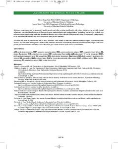
Technique for Determining the Metrological Characteristics of the Comparator. There are the selection of the signal of the currents difference in the measuring circuit of the comparator, its measurement and the determination of the orthogonal components (projections on the real and imaginary axis) when determining the ratio error and phase displacement [5]. The measurement of the reference signal and determination of its orthogonal components simultaneously occurs. It is necessary to measure the current in the circuit for the reference current transformer and the current in the circuit for the currents difference to determine the errors and measurement uncertainties when calibrating this instrument in accordance with [3]. These operations are realized by means of resistance measure and resistance decade box. The signal on potential terminals of resistance measure and the voltage on the terminals of the resistance box is measured using a precision multimeter. Although it is possible to use a comparator itself as a reference current meter which must be pre-calibrated for this parameter. A two-channel oscilloscope is used to measure the phase shift angle between these signals that is the most complicated measuring operation. Let's consider in more detail the relationship between the output signals of the comparable current transformers. The curve of the currents difference changes the polarity at the moment of mutual intersection of the curves of the compared signals that is poured into four characteristic variants of the disposition of the voltage curves at the output terminals of the resistance measure and the terminals of the resistance box relative to each other. Below are the images of such combinations for analysis without respecting the scale. It is necessary to scale the input voltage signals before the angle between them and the time axis will be closer to 90 degrees in order to obtain a clearer image on the oscilloscope's screen. The time scale must be performed in such a way as to achieve the optimum correlation between the uncertainty of the interference and the accuracy of the time interval definition between the signals. It is advisable to consider four variants of combinations of input signals to the comparator. Fig. 1a shows a combination when the output signal of the calibrated current transformer exceeds the amplitude and ahead of the phase of the reference current transformer signal.
b
a
c Fig. 1.
http://ws-conference.com/
№ 4(32), Vol.2, April 2018
43
WORLD SCIENCE
ISSN 2413-1032
Fig. 2a shows a combination when the output signal of the reference current transformer is smaller in amplitude and ahead of the phase of the calibrated current transformer signal.
b
а
c Fig. 2.
In the first case, the ratio error and phase displacement displayed on the comparator display will be positive. The on-screen oscilloscope will display the form of sinusoidal voltage signals at the output terminals of the resistance measure and resistance box (see Fig. 1b). At that, the curve of the reference signal will be late for the phase relative to the signal of the currents difference, that is, this curve will be on the right at the moment of crossing the time axis. In vector form, such a combination can be represented as in Fig. 1c. In the second case, the ratio error displayed on the comparator display will also have a positive value, in contrast to the negative phase displacement. The image of sinusoidal voltage signals on the oscilloscope's screen will be close to Fig. 2b. At that, the curve of the reference signal will outpace the signal of the currents difference by phase, that is, this curve will be on the left at the moment of crossing the time axis. In vector form, such a combination can be represented as in Fig. 2c. Fig. 3a shows a combination when the output signal of the reference current transformer exceeds the amplitude and ahead of the phase of the calibrated current transformer signal.
b
а
c Fig. 3.
44
№ 4(32), Vol.2, April 2018
http://ws-conference.com/
WORLD SCIENCE
ISSN 2413-1032
In this case, the ratio error and phase displacement values displayed on the comparator display will be negative. The image of sinusoidal voltage signals on the oscilloscope's screen corresponds to Fig. 3.b. These signals will be in the phase opposite phase and the reference signal curve outstrips the signal of the currents difference, that is, this curve will be on the right when the time axis will be intersected. In vector form, such a combination can be represented as in Fig. 3c. Fig. 4a shows a combination when the calibrated output signal is smaller in the amplitude and ahead of the phase of the reference current transformer signal. In this case, the ratio error value displayed on the comparator display will have a negative value in contrast to a positive phase displacement. The image of sinusoidal voltage signals on the oscilloscope's screen corresponds to Fig. 4b. These signals will be in opposite phases and the curve of the reference current transformer signal will also outstrip the signal of the currents difference, but will be on the left at the moment of crossing the time axis. In vector form, such a combination can be represented as in Fig. 4c.
b
а
c Fig. 4.
Summarizing the above, note that the symbols of equivalent reference values according to Formulas (1) and (4) should be determined by the image on an oscilloscope associated with a graphic vector image. Evaluation of Measurement Uncertainty. According to the guide [6] , the measurement uncertainty of reference value of ratio error should be estimated through the standard uncertainties of each input quantity and their sensitivity coefficients according to the Equation (1). For the measured by precise voltmeter AC voltage, the sensitivity coefficient is determined as follows 2
kV kV cos(100 π t ) U R RM I S RM I S . cU 100 2 kV U R kV U R cos(100 π t ) 1 2 RM I S RM I S
(5)
For the measured by precise ammeter current, the sensitivity coefficient is determined by the expression
cI
k U kV U R cos(100 π t ) V R RM I S RM I S
2
100 . 2 IS kV U R kV U R R I 1 2 R I cos(100 π t ) M S M S
http://ws-conference.com/
№ 4(32), Vol.2, April 2018
(6)
45
WORLD SCIENCE
ISSN 2413-1032
To take into account measurement uncertainty from the application of the standard measure of electrical resistance, the sensitivity coefficient is as follows
cR
k U kV U R cos(100 π t ) V R RM I S RM I S
2
100 . 2 RM kV U R kV U R R I 1 2 R I cos(100 π t ) M S M S
(7)
To take into account measurement uncertainty from the application of an oscilloscope, the sensitivity coefficient is as follows
10000 π ct
kV U R sin(100 π t ) RM I S
(8)
.
2
kV U R kV U R R I 1 2 R I cos(100 π t ) M S M S To take into account the measurement uncertainty from the current branching of the current source, the coefficient of sensitivity is such 2
UR UR R I kV R I cos(100 π t ) M S . ck 100 M S 2 kV U R kV U R cos(100 π t ) 1 2 RM I S RM I S
(9)
Table 1 shows the uncertainty budget of the reference value of the ratio error, taking into account the sensitivity coefficients of Expressions (5) - (9). Table 1. Input quantity
Input quantity estimation
Standard uncertainty иі
Sensitivity coefficient сі
Contribution to uncertainty
UR
U R U
сU
cU SU , cU uU
IS
IS I M R
SU , uU SI , u I
cI
cI S I , cI uI
иR St , utut
сR сt
сR иR cI St , сt ut
иk
сk
сk иk
Coverage factor
Expanded uncertainty
k ≈2, Р =95 %
k ·иε
RM t kV
t k V
Output quantity
Measurement result
Combined standard uncertainty
εI
Equation (1)
uε
5 2 i
c
ui2
i 1
The following notation and their definitions are used in Table 1. SU , SI , St are the standard deviations of the arithmetic mean of the measured voltage and current and the time interval between the comparator input signals, respectively; M , k are type B estimations of the value of the reference resistance measure and the R V factor, which takes into account the current branching when measuring the voltage, respectively;
46
№ 4(32), Vol.2, April 2018
http://ws-conference.com/
WORLD SCIENCE
ISSN 2413-1032
u R , uk , ut are standard uncertainties in the calibration of the reference resistance measure and the current branching factor and time interval between the comparator input signals that estimated by type B; uε is combined standard uncertainty in determining the reference value of the ratio error . The measurement uncertainty of reference value of phase displacement should be estimated through the standard uncertainties of each input quantity and their sensitivity coefficients according to the Equation (4). For the reference value of the ratio error the sensitivity coefficient is determined as follows
kV2 U R2 1 2 2 ε I 200 εI 2 2 200 1 200 RM I S 1 100 100 1
cε
2
ε 1 I 2 2 kV U R 1 100 1 εI . 2 2 2 2 1 ε I 2 RM I S 1 100 100
(10)
To take into account the measurement uncertainty from the current branching of the current source, the coefficient of sensitivity is such
kV U R2
ck =
RM2 I S2 (1
εI ) 100
1
2
εI 2 2 1 k U 1 100 V R 1 εI . 2 2 2 2 1 ε I 2 RM I S 1 100 100
(11)
For a measured AC voltage by means of precision multimeter, the sensitivity coefficient is determined so
kV2 U R
cU =
RM2 I S2 (1
εI ) 100
1
2
ε 1 I 2 2 kV U R 1 100 1 εI . 2 2 2 2 1 ε I 2 RM I S 1 100 100
(12)
To take into account measurement uncertainty from the application of the standard measure of electrical resistance, the sensitivity coefficient is as follows
cR =
kV2 U R2 RM3 I S2 (1
εI ) 100
1 2
ε 1 I 2 2 kV U R 1 100 1 εI . 2 2 2 2 1 ε I 2 RM I S 1 100 100
(13)
For measured current by means of comparator, the sensitivity coefficient is determined by the expression
http://ws-conference.com/
№ 4(32), Vol.2, April 2018
47
WORLD SCIENCE
ISSN 2413-1032
kV2 U R2
cI =
RM2 I S3 (1
1 εI ) 100
ε 1 I 2 2 kV U R 1 100 1 εI 2 2 2 2 1 ε I 2 RM I S 1 100 100
2
.
(14)
Table 2 shows the uncertainty budget for reference value of the phase displacement based on the sensitivity coefficients Expressions (10) - (14). Table 2. Input quantity
Input quantity estimation
Standard uncertainty иі
Sensitivity coefficient сі
Contribution to uncertainty
εI
εI k V
uε
сε
cε uε
сk
сk иk cU SU , cU uU
kV RM
U R U M R
IS
IS I
иk SU , uU иR SI , u I
Output quantity
Measurement result
Combined standard uncertainty
φ
Equation (4)
uΔφ
UR
сU сR
сR иR cI S I , cI uI
cI Coverage factor
Expanded uncertainty
k ≈2, Р =95 %
k ·иΔφ
5 2 i
c
ui2
i 1
The following notation and its definition is applied in Table 2 . uΔφ is combined standard uncertainty in determining the reference value of phase displacement. Research Results. The laboratory of the State Enterprise "Ukrmetrteststandart" conducted an experimental study of several comparators in accordance with the above method. A precision multimeter 8846A, manufactured by Fluke Corp. was used to measure the voltage on the terminals of the resistance decade box P529, manufactured by the plant "Tochelectroprylad". The current through the circuit for the reference current transformer was measured using the built-in meter of the comparator itself, the metrological characteristics of which was previously determined. Measurement results and measurement uncertainties are given in Table 3 and Table 4. Table 3. Input quantity
UR IS RM t kV
Input quantity estimation 1,017 V
Standard uncertainty иі 0,002 V
Sensitivity coefficient сі -0,033 %/V
Contribution to uncertainty 0,000066 %
3,062 А
0,010 А
0,011 %/А
0,000109 %
1000,0 Ω 0,00038 s 1,010
1,0 Ω 0,00010 s 0,002 Combined standard uncertainty 0,000193 %
0,000033 %/Ω 1,254 %/s -0,033
0,000033 % 0,000125 % 0,000066 % Expanded uncertainty 0,000386 %
Output quantity
Measurement result
εI
-0,03331 %
Coverage factor k ≈2, Р =95 %
Standard uncertainties for each input quantity are given taking into account the corrections and standard deviations of meters readouts. Compared with the results set forth in [2], the values of measurement uncertainty are much lower, but in this case the accuracy of the comparator is checked
48
№ 4(32), Vol.2, April 2018
http://ws-conference.com/
WORLD SCIENCE
ISSN 2413-1032
without taking into account the loading effect, which causes a change in the metrological characteristics of the current transformer for these conditions. Table 4 Standard uncertainty Contribution to Sensitivity coefficient сі иі uncertainty εI 0,000193 % 0,0834 1/% 0,16·10-6 kV 0,002 0,00277 5,58∙10-6 -1 UR 0,002 V 0,00277 V 5,54∙10-6 RM 1,0 Ω -0,0000028 Ω-1 2,82∙10-6 -1 IS 0,010 А -0,00092 А 9,20∙10-6 Combined standard Expanded Output quantity Measurement result Coverage factor uncertainty uncertainty Δφ 39,95∙10-6 12,43·10-6 k ≈2, Р =95 % 24,86∙10-6 Input quantity
Input quantity estimation -0,03331 % 1,010 1,017 V 1000,0 Ω 3,062 А
The standard uncertainty of the ratio error is estimated at the previous calibration stage. Similarly to the previous characteristic, when compared with the results set forth in [2], the value of measurement uncertainty is much less because of mentioned above circumstances. It should be noted separately that the value of the resistance decade box at the industrial frequency should also be estimated for the correct determination of the reference values as well as measurement uncertainty of this measurement. With regard to the branching factor kV, it can be said that a better evaluation of the input impedance of a precision multimeter can significantly reduce the resulting measurement uncertainty. Conclusions. It is possible to achieve satisfactory measurement uncertainties with the help of the proposed method of calibrating the AC comparators. Metrological traceability establishes connection with the standards of physical units of alternating voltage, alternating current, electrical resistance, time and frequency. There is space for this method to reduce the measurement uncertainty due to improved estimation of the branching factor, the use of shielded rooms, a stabilized current source and power supply. This method allows us to estimate the metrological characteristics of AC comparator in specific conditions, however, for the correct determination of the metrological characteristics of current transformer with the use of such a comparator, the loading effect of its measuring circuits on the values of the errors of this current transformer should be evaluated. REFERENCES 1. IEC 61869-1, International standard. Instrument transformers – Part 1: General requirements, Geneva: International Electrotechnical Commission, 2007, 134 p. 2. Isaiev, V. “FINDING REFERENCE VALUES TO CALIBRATE TWO ALTERNATING CURRENTS COMPARATOR.” International Scientific and Practical Conference World science. Vol. 1. No. 2. ROST, 2018. 3. Isaiev, V. “The problem of defining comparation accuracy of AC current amplitude values.” Science and Education a New Dimension. Natural and Thechnical Sciences. V(13). Issue: 121. 2017, P. 57-60. 4. Isaiev, V. “The method of measuring the phase shift angle between two voltages using a precision voltmeter.” Ukrainian Metrological Journal. No. 2. 2017, P. 3-7. 5. AMAK.411439.001 РЭ. Comparator CA507. Manual. Part 1, Kiev, “Oltest” LLC, 86 p. 6. JCGM 100:2008 (GUM 1995), Evaluation of measurement data – Guide to the expression of uncertainty in measurement , Joint Committee for Guides in Metrology, 2008, 134 p.
http http://ws-conference.com/ ://ws-conference.com/
№ 4(32), Vol.2, April 2018 № 2(30), Vol.1, February