microcontroller algorithm has been implemented using the C programming language to emulate a typical peak sensing analog
Microcontroller Based Control Signal Generation for use in Valve Audio Dynamic Range Compression Applications Armando Cevolatti, School of Electrical and Computer Engineering, RMIT University, Australia
Abstract—This paper explores the development of a valve variable gain amplifier and microcontroller based side-chain for use in an audio dynamic range compressor. The microcontroller algorithm has been implemented using the C programming language to emulate a typical peak sensing analogue compressor side-chain circuit. The resultant control signal is also demonstrated as suitable for real-time control of the gain of a semi-remote cut-off valve amplifier stage. Future work will see the development of unique microcontroller based side-chain algorithms as well as emulation of other analogue side-chain topologies such as opto-attenuator architectures.
A
This might be the natural attack and decay function of an opto-attenuator or the time constant of a modest resistorcapacitor (RC) circuit. The use of a standalone microcontroller allows for the emulation of a variety of sidechain architectures with in a single package and the potential development of unique side-chain characteristics while maintaining an analog audio signal path. II. SIDE-CHAIN EMUALATION
I. INTRODUCTION
UDIO dynamic range compressors operate to automatically control the amplitude of an audio signal in real time, faster and more predictably than can be achieved manually on a mixing console [1]. A typical compressor is comprised of two major elements; a sidechain circuit and a variable gain amplifier controlled by the side-chain circuit [2]. In a typical feed-forward compressor architecture, the side-chain detects the amplitude of the incoming audio signal; if the audio level exceeds a given threshold level, the side-chain generates a control signal that reduces the gain of the variable gain amplifier relative to over-threshold level of the incoming signal. This action typically occurs over a given period (in the order of milliseconds) known as the attack time. As the input signal amplitude decreases, the control signal level is reduced over a given period, generally greater than the attack time, known as the release time. Compression use is common in audio recording studios and is applied to a single track, a group of tracks, or stereo master track for either corrective or creative applications [1]. This paper focuses on the emulation of an analogue sidechain circuit within a standalone microcontroller to provide real time control of the gain of a semi-remote cut-off valve variable gain amplifier. The use of semi-remote cut-off valves as variable gain amplifiers in in compressors dates back to designs of the 1950’s such as the Fairchild 670 and remains popular in contemporary compressor designs. [3,4]. Along with the audio signal path and variable gain amplifier selection, side-chain architecture influences the sonic characteristic of the compressor, with particular sonic characteristics preferred for certain program material [5]. The side-chain characteristic is influenced by the audio detection method, be it RMS, peak or average sensing, along with the temporal characteristics of the side-chain circuit.
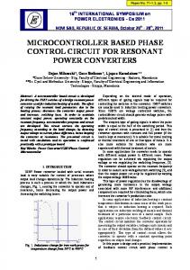
Fig 1. Functional block diagram of a typical analogue peak-sensing side-chain emulated using the Analog Devices ADuC7024.
An Analog Devices ADuC7024 precision microcontroller has been used to emulate the function of the typical sidechain circuit shown in figure 1 [1]. This microcontroller has been selected for its high-speed 12-bit ADC and 12-bit DAC peripherals [6]. The software is written in C using unsigned fixed point processing for transportability across a variety of microcontroller platforms. In order to optimize processing time, the algorithm has been constructed using simple compound and parabolic functions to emulate the complex exponential soft-knee and RC circuit transfer functions. This eliminates the need for calls to math.h library functions, or the use of extensive exponential function look up tables. The transfer function of the side-chain model can be described as an amalgam of the temporal and steady state transfer characteristics shown in figure 2 [2]. A. Signal Detection and Rectification The input audio signal, offset by ADC VREF/2 is read by an onboard 12-bit ADC into the variable inAudio. The negative portion of the audio signal swing is represented by values below 0x800, while values between 0x800 and 0xFFF represent positive going audio signals. The most significant bit of inAudio is toggled. The effect is two fold, shifting the range of positive going signals to between 0 and 0x7FF, while flagging negative going signals. In order to rectify the negative values, the compliment of the flagged value is found and the flag bit removed. The rectification process results in an 11-bit representation of the input audio signal instantaneous voltage.
(samples)
τatt'
τrel' '
Cout'
soft'knee' Soft knee: Klow>1; knee = kneehigh-kneelow; knee_coeff = 0x1FFF; if ((inAudio > kneelow) && (inAudio < kneehigh) { knee_coeff *= (inAudio - kneelow); knee_coeff /= knee; } if (inAudio < kneelow) knee_coeff = 0x0000; C_outMem = C_out; C_out = 0x0000; if (knee_coeff != 0x1FFF) C_out = ((knee_coeff) * (inAudio - kneelow))>>1; else if (inAudio > threshold) C_out = knee_coeff * (inAudio - threshold); if (C_out > C_outMem) C_out = C_outMem + ((C_out - C_outMem)/(attack)); else C_out = C_outMem - ((C_outMem - C_out)/(release));
Fig. 3. C implementation of the soft-knee peak-detecting side-chain emulation algorithm executed in the ADuC7024.
III. VARIABLE GAIN VALVE AMPLIFIER As a consequence of the graduated spacing of the grid electrode helix, the amplification factor (µ) of a semi-remote cut-off triode such as the 12AT7 (ECC81) can be controlled by varying the bias voltage VGK applied between the valve grid and cathode [8]. In the circuit shown in figure 4 the operational amplifier output connects to the cathode of each triode in the long-tailed-pair via a 300Ω cathode resistor RK (R4). 470kΩ resistors are used to hold the grid of each triode at 0V. Under normal bias conditions, the operational amplifier output is set to 0V, resulting in 10mA of current through RK, producing VGK of -3V. As the control signal is increased, VGK decreases and so to does the gain of the circuit as the operating point approaches cut-off.
attack time could be adjusted between approximately 0.28msec and 119msec, while the release time could be adjusted between 37msec and 2200msec. The threshold level was adjustable over a 40dB range. Simulation results indicate that the ADuC7024’s 0V to 3.3V DAC output scaled and buffered by an operational amplifier could be used to vary the gain of the 12AT7 longtailed pair circuit by up to 14dB. Figure 6 illustrates the simulated variation in output level for a given input signal with respect to control signal values of 0V, 1.1V, 2.2V and 3.3V applied to the circuit in figure 4.
Fig. 6. Simulation result illustrating the output of the circuit in figure 4 for a common input signal with control signal voltages of 0V, 1.1V, 2.2V and 3.3V applied.
V. CONCLUSION
Fig. 4. Variable gain amplifier circuit based on a long tailed pair circuit using semi-remote cut-off valves, the microcontroller DAC control signal is applied via an operational amplifier. IV.
RESULTS
This paper has demonstrated the development of a microcontroller-based algorithm to emulate a typical peak sensing audio dynamic compressor side-chain circuit. Many other existing analogue side-chain topologies could similarly be explored, including RMS detection models such as optoattenuator based side-chains topologies. Furthermore, there is potential to design novel side-chain algorithms that extend beyond the capabilities of analogue circuits as demonstrated in this paper through the application of a constant relative knee-to-threshold function. The application of a microcontroller based side-chain is not limited to use with a semi-remote cut-off valve variable gain amplifier stage, and could similarly be applied to solid-state audio signal path designs. REFERENCES [1] [2] [3]
Fig. 5. Steady-state and temporal control signal function measured at the ADuC7024 DAC output.
Figure 5 illustrates the measured temporal and steady state control signal output of the microcontroller DAC. The steady state transfer function was generated in response to a 2kHz sine wave with linearly increasing amplitude applied at the ADC input. The temporal transfer function was generated in response to a 200msec 2kHz pulse at the ADC input. Using the user interface potentiometers, the measured
[4] [5] [6] [7] [8]
A.Tutton, Ed. M. Talbot-Smith Audio Engineers Reference Book, Oxford: Focal Press, 1995 F. Floru “Attack and Release Time Constants in RMS-Based Feedback Compressors” in 104th Audio Eng. Soc. Convention, 1998 Fairchild Recording Equipment Corporation 670 Dual Limiter Schematic, New York: Fairchild Recording Equipment Corporation [Schematic Diagram] c1959 Manley Laboratories Inc. Manley Variable MU Stereo Limiter/Compressor, Manley Laboratories Inc. [Online (viewed 2012, Mar)] available at: http://www.manley.com/mslc.php M. Senior (2009, Sept.) Classic Compressors: Choosing the Right Compressor for the Job, Sound On Sound [Online] available at: www.soundonsound.com/sos/sep09/articles/classiccompressors.htm Analog Devices Inc, Precision Analog Microcontroller, 12-Bit Analog I/O, AMRTDMI® MCU: ADuC7019/20/21/22/24/25/26/27/28; Revision B. (Data Sheet), Analog Devices Inc, 2005 THAT Corporation “A simple/effective soft knee compressor limiter” Design Note 107/111 Revision 3, THAT Corporation, 2000 E. Lurch Fundamentals of Electronics, 2nd ed. NewYork: John Wiley and Sons Inc. 1971