Sep 3, 2009 - in the component-based system Treaty will be the major task of this diploma ...... nent using different interfaces of the port Clock.dateformatter.
Faculty of Computer Science Institute of Software- and Multimedia-Technology, Software Technology Group
Diploma Thesis
MODEL-BASED RUN-TIME VERIFICATION OF SOFTWARE COMPONENTS BY INTEGRATING OCL INTO TREATY Claas Wilke Born April, 16th 1983 in Buxtehude Mat.-Nr.: 3155376
Supervised by:
Dr.-Ing. Birgit Demuth Professor
Prof. Dr. rer. nat. habil. Uwe Aßmann Submitted on September 3, 2009
II
ABSTRACT Model Driven Development is used to improve software quality and efficiency by automatically transforming abstract and formal models into software implementations. This is particularly sensible if the model’s integrity can be proven formally and is preserved during the model’s transformation. A standard to specify software model integrity is the Object Constraint Language (OCL). Another topic of research is the dynamic development of software components, enabling software system composition at component run-time. As a consequence, the system’s verification must be realized during system run-time (and not during transformation or compile time). Many established verification techniques cannot be used for run-time verification. A method to enable model-based run-time verification will be developed during this work. How OCL constraints can be transformed into executable software artifacts and how they can be used in the component-based system Treaty will be the major task of this diploma thesis. The work contains: • An introduction into the theoretical foundations, • An investigation of related work, • The requirement analysis and a prototypical design of a run-time verification process, • A prototypical implementation of the designed system, • And its validation using an example case.
III
IV
V
VI
CONTENTS Abstract
III
1 Introduction
1
2 Foundations
5
2.1 Verification vs. Validation
. . . . . . . . . . . . . . . . . . . . . . . . . . . . . . . .
5
2.1.1
Software Verification . . . . . . . . . . . . . . . . . . . . . . . . . . . . . . .
5
2.1.2
Software Validation . . . . . . . . . . . . . . . . . . . . . . . . . . . . . . . .
6
2.1.3
Run-time Verification . . . . . . . . . . . . . . . . . . . . . . . . . . . . . . .
6
2.2 The Object Constraint Language . . . . . . . . . . . . . . . . . . . . . . . . . . . .
7
2.3 The Generic Three Layer Metadata Architecture . . . . . . . . . . . . . . . . . . . .
7
2.4 Two Ways to Verify Contracts at Run-time . . . . . . . . . . . . . . . . . . . . . . .
9
2.4.1 The Interpretative Approach . . . . . . . . . . . . . . . . . . . . . . . . . . .
9
2.4.2 The Generative Approach . . . . . . . . . . . . . . . . . . . . . . . . . . . .
9
2.5 Dresden OCL . . . . . . . . . . . . . . . . . . . . . . . . . . . . . . . . . . . . . . .
9
2.5.1 The Dresden OCL Toolkit . . . . . . . . . . . . . . . . . . . . . . . . . . . .
11
2.5.2 The Dresden OCL2 Toolkit . . . . . . . . . . . . . . . . . . . . . . . . . . . .
11
2.5.3 Dresden OCL2 for Eclipse . . . . . . . . . . . . . . . . . . . . . . . . . . . .
11
2.6 A Motivating Example . . . . . . . . . . . . . . . . . . . . . . . . . . . . . . . . . .
13
VII
2.7 The Consumer/Supplier Role Model . . . . . . . . . . . . . . . . . . . . . . . . . .
15
2.8 Aspect-Oriented Programming . . . . . . . . . . . . . . . . . . . . . . . . . . . . .
20
2.9 The Eclipse/OSGi Component Model . . . . . . . . . . . . . . . . . . . . . . . . . .
21
2.9.1 The Extension Point Schema . . . . . . . . . . . . . . . . . . . . . . . . . .
21
2.9.2 The Plug-in.xml File . . . . . . . . . . . . . . . . . . . . . . . . . . . . . . .
22
2.10 Eclipse Equinox Aspects . . . . . . . . . . . . . . . . . . . . . . . . . . . . . . . . .
25
2.10.1 The Equinox Architecture . . . . . . . . . . . . . . . . . . . . . . . . . . . .
25
2.10.2 The Equinox Aspects Project . . . . . . . . . . . . . . . . . . . . . . . . . .
25
3 Run-Time Verification Approaches
27
3.1 Treaty . . . . . . . . . . . . . . . . . . . . . . . . . . . . . . . . . . . . . . . . . . . 3.1.1
Contract Definition . . . . . . . . . . . . . . . . . . . . . . . . . . . . . . . .
28
3.1.2
Contract Vocabularies . . . . . . . . . . . . . . . . . . . . . . . . . . . . . .
28
3.2 The CALICO Approach . . . . . . . . . . . . . . . . . . . . . . . . . . . . . . . . . .
30
3.3 Run-Time Error Detection in the Trader Project . . . . . . . . . . . . . . . . . . . .
31
3.4 The Satin Approach . . . . . . . . . . . . . . . . . . . . . . . . . . . . . . . . . . . .
32
3.5 Constraint Monitoring in USE . . . . . . . . . . . . . . . . . . . . . . . . . . . . . .
32
3.6 The RISC System . . . . . . . . . . . . . . . . . . . . . . . . . . . . . . . . . . . . .
33
3.7 The Java Modeling Language . . . . . . . . . . . . . . . . . . . . . . . . . . . . . .
34
3.8 The Contracting System ConFract
. . . . . . . . . . . . . . . . . . . . . . . . . . .
35
3.8.1 Requirements in ConFract . . . . . . . . . . . . . . . . . . . . . . . . . . . .
35
3.8.2 The Contract Language CCL-J . . . . . . . . . . . . . . . . . . . . . . . . . .
35
3.8.3 Contract Closure and Checking . . . . . . . . . . . . . . . . . . . . . . . . .
36
3.9 Snapshot Verification for CORBA components
VIII
27
. . . . . . . . . . . . . . . . . . . .
36
3.10 The PECOS Approach . . . . . . . . . . . . . . . . . . . . . . . . . . . . . . . . . .
37
3.11 Run-time Verification in EJB . . . . . . . . . . . . . . . . . . . . . . . . . . . . . . .
37
3.12 Architectural Constraints in MADAM . . . . . . . . . . . . . . . . . . . . . . . . . .
38
3.13 Summary . . . . . . . . . . . . . . . . . . . . . . . . . . . . . . . . . . . . . . . . .
38
CONTENTS
4 Analysis and Architectural Design
41
4.1 Requirement Analysis . . . . . . . . . . . . . . . . . . . . . . . . . . . . . . . . . .
41
4.1.1
Contract Definition Requirements . . . . . . . . . . . . . . . . . . . . . . .
41
4.1.2
Contract Verification Requirements . . . . . . . . . . . . . . . . . . . . . . .
42
4.1.3
Delimited Features . . . . . . . . . . . . . . . . . . . . . . . . . . . . . . . .
43
4.2 Evaluation and Decision of Required Resources . . . . . . . . . . . . . . . . . . . .
43
4.2.1 Possible Domain-Specific Languages . . . . . . . . . . . . . . . . . . . . . .
44
4.2.2 Required Model Instance Types . . . . . . . . . . . . . . . . . . . . . . . . .
49
4.2.3 OCL Constraint Integration . . . . . . . . . . . . . . . . . . . . . . . . . . .
50
4.3 Discussion of Multiple Software Architectures
. . . . . . . . . . . . . . . . . . . .
52
4.3.1 Adapting the OCL2 Interpreter as a Treaty Vocabulary . . . . . . . . . . . .
53
4.3.2 Generating JUnit Test Code for Treaty Using the Java Code Generator . . .
55
4.3.3 Generating Aspect Code Using the Java Code Generator . . . . . . . . . .
56
4.3.4 Architectural Design Decision . . . . . . . . . . . . . . . . . . . . . . . . . .
58
5 Design and Implementation
59
5.1 Refactoring of the Treaty Architecture . . . . . . . . . . . . . . . . . . . . . . . . .
59
5.1.1
Problems of the Current Treaty Architecture . . . . . . . . . . . . . . . . . .
59
5.1.2
The Refactored Treaty Architecture . . . . . . . . . . . . . . . . . . . . . . .
60
5.2 Treaty OCL Vocabulary Implementation . . . . . . . . . . . . . . . . . . . . . . . .
62
5.2.1 The Taxonomy of the OCL Vocabulary . . . . . . . . . . . . . . . . . . . . .
62
5.2.2 The Implementation of the Vocabulary Interface . . . . . . . . . . . . . . .
63
5.3 Java Meta-Model Adaptation . . . . . . . . . . . . . . . . . . . . . . . . . . . . . .
65
5.3.1 Different Possible Adaptations . . . . . . . . . . . . . . . . . . . . . . . . .
65
5.3.2 The Realized Adaptation . . . . . . . . . . . . . . . . . . . . . . . . . . . . .
66
5.4 Context Information Capturing and Adaptation
. . . . . . . . . . . . . . . . . . . .
69
5.4.1 Aspect-Oriented Information Retrieval . . . . . . . . . . . . . . . . . . . . .
69
5.4.2 Service-Based Information Capturing . . . . . . . . . . . . . . . . . . . . . .
71
5.5 Refactoring of Dresden OCL2 for Eclipse . . . . . . . . . . . . . . . . . . . . . . .
71
CONTENTS
IX
5.5.1 Changes in the Model to Model Instance Relationship . . . . . . . . . . . .
73
5.5.2 Refactoring of the Model Instance Architecture . . . . . . . . . . . . . . . .
77
5.5.3 Refactoring of the Java Model Instance Type . . . . . . . . . . . . . . . . .
77
5.5.4 Refactoring of the OCL2 Interpreter . . . . . . . . . . . . . . . . . . . . . .
78
6 Testing
81
6.1 Testing the Treaty OCL Vocabulary . . . . . . . . . . . . . . . . . . . . . . . . . . .
81
6.2 Testing the Adapted Java Meta-Model . . . . . . . . . . . . . . . . . . . . . . . . .
84
6.3 Testing Snapshot Verification . . . . . . . . . . . . . . . . . . . . . . . . . . . . . .
85
7 Evaluation and Future Works 7.1
7.2
7.3
87
Evaluation . . . . . . . . . . . . . . . . . . . . . . . . . . . . . . . . . . . . . . . . .
87
7.1.1
Contract Definition Requirements . . . . . . . . . . . . . . . . . . . . . . .
87
7.1.2
Contract Verification Requirements . . . . . . . . . . . . . . . . . . . . . . .
90
7.1.3
Delimited Features . . . . . . . . . . . . . . . . . . . . . . . . . . . . . . . .
90
Future Works and Scientific Challenges . . . . . . . . . . . . . . . . . . . . . . . .
90
7.2.1
Future Works on Treaty . . . . . . . . . . . . . . . . . . . . . . . . . . . . .
90
7.2.2
Future Works on the Treaty OCL Vocabulary . . . . . . . . . . . . . . . . . .
91
7.2.3
Future Works on Dresden OCL2 for Eclipse . . . . . . . . . . . . . . . . . .
91
7.2.4
Scientific challenges . . . . . . . . . . . . . . . . . . . . . . . . . . . . . . .
92
Summary and Conclusion . . . . . . . . . . . . . . . . . . . . . . . . . . . . . . . .
93
A List of Figures
XI
B List of Tables
XV
C List of Listings
XVII
D List of Abbreviations
XIX
Bibliography
XXI
Confirmation
XXIX
X
CONTENTS
1
INTRODUCTION Even if proof techniques and tools eventually become available, one may suspect that run-time checks will not go away, if only to cope with hard-to-predict events such as hardware faults, and to make up for possible bugs in the proof software itself [...] Betrand Meyer [Mey97, p. 399]
Since programming has lead to source code being too large to be structured in a single file in a readable way, software engineers have been trying to structure their software more efficiently. In the 1970s, Software Modules [Par72] became popular to structure software more intelligent, readable and secure. Examples for modular programming languages are Modula-2, Delphi, Pascal and Ada-83 [Aßm03, p. 64f]. The next step towards powerful programming languages was Object-oriented Programming [Mey97] which organizes the software modules in a more intuitive and logical way and introduces the concept of object initialization at run-time. Examples for object-oriented programming languages are ADA-95, Sather, C++ and Java [Aßm03, p. 3]. Software Components [Szy02] can be used “to encapsulate data and programs into [boxes] that operate[s] predictable [BJPW99].” Software components can be considered as a higher programming paradigm than object-oriented programming, because they improve modularity, interface standardization and provide more dynamic connection mechanisms [Aßm03, p. 67]. According to Szyperski [Szy02, p. 35ff], a software component is a unit of independent deployment that is well separated from its environment and other components and can be of third-party composition. A software component has no (externally) observable state and encapsulates its implementation. It communicates with the environment via well-defined interfaces. A software component can be loaded into and activated in a particular system. Software components are highly modular and interchangeable. “[...] one component may replace another even if it has a different internal implementation, as long as its specification includes he interfaces that the client component requires.” [LC02, Sect. 1] Components of that only the interfaces are visible are called Blackbox Components. Components that provide also access to their internal structure are called Whitebox Components instead. Also hybrid components, so-called Graybox Components exist [Szy02, p. 544ff]. In this work the term Component will represent blackbox components. Component-Based Software Engineering (CBSE) is becoming a mainstream approach. The advantages of CBSE are quicker development times, secure investments through reuse of existing components and the ability to compose software interactively [GZ01]. Component-based software is portable, interoperable, extensible, configurable and maintainable [LSNA97]. A central question in CBSE is how to trust foreign or third-party components. Beugnard [BJPW99] points out that mission-critical systems cannot be rebooted easily if an error occurs during their run-time
1
and some components may behave unexpectedly. Thus, we have to determine whether we can trust and use given components before and during component interaction. We need the ability to verify that software components conform to their specification [Hei03], some sort of high-quality specifications in the middle, often called Contracts [Szy00]. A contract “[...] protects the client by specifying how much should be done [... and] the contractor by specifying how little is acceptable [...]” [Mey92, p. 41] Contracts are a well-known mechanism for achieving trustworthy software [ABH+ 06, Mey97]. Traditionally, collaborations in component models are described by interface compatibility [DJ08]. “Technically an interface is a set of operations that can be invoked by clients.” [Szy02, p. 50] An interface defines which methods are provided and required by a component to interact with other components. Such interfaces can be regarded as syntactic contracts. “The notion of contracts as interfaces–annotated with pre- and postconditions and, perhaps, invariants–is simple and practical. However several important issues are not covered.” [Szy02, p. 55] Besides, interface compatibility contracts can be defined on properties of software instances. Changes of object states at run-time can invalidate properties and contracts at run-time [ABH+ 06, p. 155]. Contracts defined on properties of instances can be considered as Dynamic Contracts [ABH+ 06, p. 157]. In modern component systems components can be dynamically discovered, loaded, started, terminated and unloaded. Thus, other types of contracts are required as well. “[... C]ontracts need to go far beyond establishing functional requires and provides clauses.” [Szy00] Beugnard [BJPW99] separates component contracts into four categories:
1. Basic Syntactic Contracts: Syntactic contracts define the interfaces components provide to communicate with other components. Traditionally, a description language like the Interface Definition Language (IDL) or an object-oriented programming language like Java can be used to define such interfaces. 2. Behavioral Contracts: Besides the interface definition, the component user has to ensure that the used component does what the component is expected to do. “You can never be sure the component will perform correctly, only that it will perform as specified.” [BJPW99] Thus, behavioral contracts are used to define the component semantics. Typically, such Design by Contract [Mey97, p. 331ff] is realized by defining pre- and postconditions in constraint languages like Eiffel [ECM06] or the Object Constraint Language (OCL) [OMG06c]. “The client has to establish the precondition before calling the operation and the provider can rely on the precondition being met whenever the operation is called. The provider has to establish the postcondition before returning to the client and the client can rely on the postcondition being met whenever the call to the operation returns.” [Szy02, p. 53] 3. Synchronization Contracts: In multi-user scenarios or distributed systems synchronization contracts are used to ensure that the components communicate in the right order. Parallelism, and sequences of method execution can be defined. Synchronization in terms of transactional behavior can be realized as well. 4. Quality of Service Contracts: A fourth group of contracts defines Quality of Service (QoS) requirements that are commonly known as Non-Functional or Extra-Functional requirements. E.g., QoS contracts can define response times or result throughputs for multiobject answers.
Dietrich [DJ08] names some other types of contracts besides the four categories depicted by Beugnard, including Security, Trust and Licensing. Aßmann et al. [ABH+ 06] point out that contracts defined on software connections can be separated in Simple and Multi-Point Contracts. Simple contracts focus on one extension or connection of components whereas multi-point contracts focus on combinations of extensions.
2
Chapter 1 Introduction
As mentioned above, one possibility to design behavioral contracts is the Object Constraint Language (OCL) [OMG06c]. A tool for supporting OCL constraints defined on models in different Domain-Specific Languages (DSLs) (e.g., UML or EMF Ecore) is Dresden OCL2 for Eclipse. A contract system to define functional and non-functional constraints on software components and to evaluate them at component run-time is provided by the contract language Treaty [DJ08, URL09s]. This work presents an approach to extend the contracting language Treaty with the definition of OCL constraints by combining Dresden OCL2 for Eclipse with Treaty. It is examined how OCL can be used for run-time verification of behavioral contracts on components. A solution that is independent of the underlying component language and implementation is presented. This work is structured as follows: Chapter 2 introduces some foundations like the Object Constraint Language (OCL) and presents a motivating example for the definition of behavioral constraints using OCL. Chapter 3 discusses related work and systems that have already been trying to realize run-time verification on component systems or have investigated similar research tasks. Chapter 4 analyses the requirements and discusses different architectural designs that could be used to combine Dresden OCL2 for Eclipse and Treaty. In Chapter 5 some implementation details are documented and explained. Chapter 6 illustrates how the implementation presented in this work has been tested. Chapter 7 finishes the work by shortly summarizing and evaluating the presented work and highlighting some challenges for future works. Typographical and graphical conventions used in this work: • Italics are used to highlight important keywords and scientific terms. • Typewriter font is used to sign model elements or language constructs of different programming and modeling languages such as Java or OCL. • Small typewriter font is used to show coding examples in listings. • Small, blue, bold typewriter font is used to highlight keywords in listings. • Small, red typewriter font is used to highlight strings in listings. • Small, green typewriter font is used to highlight comments in listings. • Blue color is used to denote hyperlinks between references. • Class diagrams and component models are illustrated according to the Unified Modeling Language (UML) [OMG09c]. A good introduction into UML can be found in the book UML@Work by Martin Hitz et al. [HKKR05] and in The Unified Modeling Language Reference Manual by James Rumbaugh et al. [RJB04]. • The illustration of role models was inspired by Riehle et al. [RG98].
3
4
Chapter 1 Introduction
2
FOUNDATIONS The difference between “theory” and “practice” is that in theory there is no difference between theory and practice, but in practice, there is. Jan L. A. van de Snepscheut and/or Yogi Bera (according to Rosenberg and Stephens [RS07, p. XXVII])
This chapter presents some theoretical foundations that are necessary to understand the content of this work. The term Verification is shortly defined and discussed with the focus on Run-time Verification in Section 2.1. In the Sections 2.2 and 2.3 the Object Constraint Language (OCL) and the Generic Three Layer Metadata Architecture are introduced. Afterwards, two different approaches to verify constraints on software objects are presented in Section 2.4. In the Sections 2.5 and 2.6 the Dresden OCL Toolkit and an example component model to explain the use of OCL constraints on component interfaces are presented. Furthermore, the Consumer/Supplier role model is introduced in Section 2.7. Additionally, the term Aspect-Oriented Programming (AOP) and the Eclipse/OSGi platform and component model are explained in the Sections 2.8 to 2.10. Readers who are familiar with these topics can skip this chapter but are recommended to have a look at the component model example in Section 2.6 to which the following chapters will refer multiple times.
2.1
VERIFICATION VS. VALIDATION
Before I discuss the tasks and results of my diploma thesis, I will shortly define a central term of my thesis: Software Verification. Furthermore, I will present the difference between software verification and Software Validation.
2.1.1
Software Verification
According to Zuser et al. [ZGK04, p. 356], Verification guarantees that results of a project development phase are consistent to the preceding project development phases. Balzert [Bal98, p. 101] and Hinzel et. al [HHMS06, p. 18] define verification as a planned and systematic process with the target to ensure that a product conforms to its requirements and its specification–that the product was developed as specified.
5
Furthermore, they conclude that Software Verification is a formal and exact method to prove the consistence between specification and implementation of a software component using mathematics [Bal98, p. 396 and p. 446]. Thus, software verification results in higher certainty for the absence of bugs than software tests [Bal98, p. 446]. The central question of software verification can be described as: “Did we develop the product right?” [Bal98, p. 101] [HHMS06, p. 18] [ZGK04, p. 356]. For software verification, only information of proceeding project phases are required and the customer or software user has not to be involved into the verification process [ZGK04, p. 356]. The basis for software verification are the functional and non-functional requirements defined during the requirement analysis [ZGK04, p. 356]. Hindel [HHMS06, p. 190] points out that instead of Software Validation, software verification can be realized for both whole software systems and single software modules or components during the whole development process. Balzert [Bal98, p. 446] names the use of assertions like pre-, postconditions, and invariants one possible form of software verification. Thus, the topic of this work, using the Object Constraint Language (including pre-, postconditions, and invariants) on software components can indeed be considered a software verification technology.
2.1.2
Software Validation
In contrast to software verification, software Validation is defined as the applicability or the value of a product in respect to its application purpose [Bal98, p. 101]. Zuser [ZGK04, p. 356] defines validation as the inspection whether or not the results of a project conform to the requirements of its customer. Hindel [HHMS06, p. 18] calls validation a planned, systematic process with the target to demonstrate that a product conforms to the planned application and environment. The central question during validation can be considered as being “Did we develop the right product?” [Bal98, p. 101] [HHMS06, p. 18] [ZGK04, p. 356]. Zuser [ZGK04, p. 356] emphasizes that the customer or user of a software has to be involved into the software’s validation. Software validation is often used as a software acceptance test [HHMS06, p. 190]. An important precondition for such a software validation by the customer is a proceeding software verification by the software developer [HHMS06, p. 190].
2.1.3
Run-time Verification
Software Validation can be considered the final step during software development while Software Verification is a continuous process during the whole software development process instead. Run-time Verification is the use of verification techniques at the developed software’s run-time. “Runtime verification supplements static analysis and formal verification with more lightweight dynamic techniques when the static techniques fail due to complexity issues. [...] Runtime verification uses some form of instrumentation to extract, during test or in operation, a trace of observations from a program run and then applies formal verification to this trace.” [FHRS08, p. 2]. In the context of run-time verification it is important to emphasize the fact that run-time verification realizes software verification during the software’s execution. Thus, run-time verification is continued after the software’s validation and will not be finished when the software development process of a software project is completed with its acceptance test and the software is shipped to the customer.
6
Chapter 2 Foundations
2.2
THE OBJECT CONSTRAINT LANGUAGE
The Object Constraint Language (OCL) is originally a “standard add-on of the Unified Modeling Language (UML)” [WK04, p. 19]. OCL enables the software developer to extend UML diagrams with additional and more precise information. New attributes, associations and methods can be defined, initial and derived values or operation bodies can be added. The main feature of OCL is a Design by Contract (DBC) [Mey97, p. 331ff] notation for the definition of preconditions (conditions which must be valid before the execution of a method), postconditions (conditions which must be valid after the execution of a method) and invariants (conditions which must be valid during the lifetime of an UML object). As mentioned above, OCL has been designed as an extension of the UML. But today, OCL is also used to define constraints on other modeling languages and DSLs. The first version of OCL was developed by IBM around 1995 [PDD+ 09]. In 1997, OCL became part of the Unified Modeling Language (UML) and was released as an Object Management Group (OMG) specification in the version 1.1 [OMG97, Wik09]. In 1999, the development of UML 2.0 and OCL 2.0 was started with the UML 2.0 and UML 2.0 OCL Request for Proposals [Wik09]. In September 2004, the 2.0 versions of UML and OCL were released. The OCL 2.0 specification has been published by the OMG and is available at the OMG website [OMG06c]. The OCL 2.1 specification is currently in development. A preview of the 2.1 specification is available at the OMG website [OMG09a]. A general and detailed introduction into OCL has been published by Warmer and Kleppe [WK04].
2.3
THE GENERIC THREE LAYER METADATA ARCHITECTURE
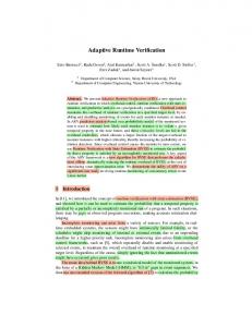
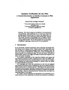
Each modeling language is defined in another language, its meta-modeling language. For example, the Unified Modeling Language is defined using the Meta Object Facility (MOF) [OMG06b], the standardized meta-meta language of the OMG. The MOF is used to describe the UML metamodel that can be used to model UML models. Generally speaking, each model requires a metamodel that is used to describe the model. The model can be instantiated by model instances (for example a UML class diagram could be instantiated by a UML object diagram). One may also say, that the model is an instance of its meta-model. This model to meta-model instance-of relationship can be considered as relative, because every model is an instance of a meta-model. The meta-model is again an instance of a meta-meta model (the meta-model’s meta-model). Each model can be enriched with OCL constraints that are defined on the model and can then be verified for instances of the model. The OMG introduced the MOF Four Layer Metadata Architecture [OMG06b][OMG09b, p. 16ff] which is used to arrange and structure the meta-model, the model, and its model instances into a layered hierarchy (see Figure 2.1; the layout of the illustration is oriented at the conceptual framework introduced by Matthias Bräuer [Brä07, p. 28]). Generally, four layers exist, the MetaMeta-Model Layer (M3), the Meta-Model Layer (M2), the Model Layer (M1), and the Model Instance Layer (M0). OCL constraints can be defined on both meta-models and models to verify models (Model-Level Constraints) respectively instances (Instance Level Constraints). Thus, the four layer metadata architecture can be generalized to a Generic Three Layer Metadata Architecture in the scope of an OCL definition (see Figure 2.2) [DW09]. On the Mn+1 Layer is the meta-model that is used to define the model that shall be constrained. On the Mn Layer is the model that is an instance of the meta-model and can be enriched by the specification of OCL constraints. Finally, on the Mn-1 Layer is the model instance on that the OCL constraints shall be verified. Please note that in the context of this generic layer architecture an instance can be both a model (like a UML class diagram) or a model’s instance (e.g., a set of objects like Java run-time objects). This is illustrated in Table 2.1.
2.2 The Object Constraint Language
7
M3
Meta-Meta-Model
M2
Meta-Model
M1
Model
M0
Model Instance
Figure 2.1: The MOF Four Layer Metadata Architecture.
Mn+1
Meta-Model
Mn
Model
Mn-1
Model Instance
Figure 2.2: The Generic Three Layer Metadata Architecture.
8
Chapter 2 Foundations
Mn+1 Mn Mn-1
Model-Level Constraints (defined on the Meta-Model Meta-Meta Model Meta-Model Model
Instance-Level Constraints (defined on the Model) Meta-Model Model Instance
Table 2.1: Constraints can be defined on both meta-models and models and thus, evaluated on models (model-level constraints) or instances (instance-level constraints). .
2.4
TWO WAYS TO VERIFY CONTRACTS AT RUN-TIME
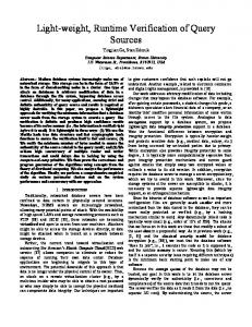
Generally, two different approaches exist to verify contracts at component run-time: the Interpretative and the Generative Approach [DW09]. The interpretative approach verifies contracts by interpreting them on a model and its instances, the generative approach instead generates code or queries that can be executed to verify the contracts. Both approaches are shortly defined in the following.
2.4.1
The Interpretative Approach
The first possible approach for contract verification is the Interpretative Approach. The interpretative approach uses a model and at least one model instance to verify the contract on this instance using an interpreter (see Figure 2.3, part A). The interpretative approach for example can be used to verify that the attribute age of an object Person is positive
2.4.2
The Generative Approach
The second possible approach is the Generative Approach. The generative approach uses a code generator to generate code that can be executed for contract verification (see Figure 2.3, part B). E.g., Java code (that ensures a set of OCL constraints defined on a UML class diagram, during code execution) could be generated. Different techniques like Aspect-Oriented Programming (AOP) or Java Assertions [GJSB05, p. 373ff] could be used.
2.5
DRESDEN OCL
The Dresden OCL Toolkit has been developed at the Technische Universität Dresden (TUD) since 1998. It provides a collection of tools that can be used by other case tool developers to integrate them into their software. E.g., the OCL2 Parser of the toolkit can be integrated into a UML Case Tool to enrich UML diagrams with OCL constraints. Today, the toolkit is one of the major software projects at the software technology group and three different versions of the toolkit have already been released. Figure 2.4 shows a time line illustrating the different releases of OCL and the Dresden OCL Toolkit.
2.4 Two Ways to Verify Contracts at Run-time
9
B: Generative Approach
Meta-Model
Model
Model Instance
Mn-1
Mn
A: Interpretative Approach
Mn+1
Meta-Model
Model
Constraints
Mn+1
Mn
Mn-1
Model Instance
Constraints
Code
Figure 2.3: The two different verification approaches. A: Interpretative Approach, B: Generative Approach.
Chapter 2 Foundations
10
Release of the Dresden OCL Tolkit Preliminary OCL Study at TUD
1995
1996
First OCL version developed by IBM
1997
1998
UML 1.1 and UML OCL 1.1 standardization
1999
Release of the Dresden OCL2 Tolkit
Start of the Dresden OCL2 Toolkit development 2000
2001
2002
Start of UML 2.0 And OCL 2.0 (Request for Proposals)
2003
Release of the Dresden OCL2 for Eclipse Development of the Pivot Model
2004
2005
2006
2007
2008
2009
UML 2.0 and UML 2.0 OCL standardization
Figure 2.4: The different releases of OCL and the Dresden OCL Toolkit.
2.5.1
The Dresden OCL Toolkit
A preliminary OCL study at the Technische Universität Dresden was done by Andreas Schmidt [Sch98] in 1998, examining how OCL could be mapped to the Structured Query Language (SQL). The first base for the toolkit was realized by Frank Finger in 1999 [Fin99, Fin00]. An OCL standard library and possibilities to load and parse UML models and OCL constraints and furthermore the possibility to generate Java code from OCL constraints were implemented. The instrumentation of the created Java code was realized by Ralf Wiebicke [Wie00]. This first released version of the toolkit was called Dresden OCL Toolkit (DOT).
2.5.2
The Dresden OCL2 Toolkit
The development of a second version of the toolkit started in 2003. The basis of this version was created with the adaptation of the Dresden OCL Toolkit to the Netbeans Metadata Repository (Netbeans MDR) by Stefan Ocke [Ock03]. This version of the toolkit was named Dresden OCL2 Toolkit (DOT2). It was based on the OCL standard in the version 2.0 [OMG06c]. The DOT2 provided the loading and parsing of UML models and OCL constraints and the transformation of constrained models into SQL [Hei05, Hei06]. The possibility to generate and instrument Java code for OCL constraints was adapted from the Dresden OCL Toolkit to the Dresden OCL2 Toolkit by Ronny Brandt in 2006 [Bra06].
2.5.3
Dresden OCL2 for Eclipse
Since 2007 the Dresden OCL2 Toolkit has been replaced by a third version. The implementation of a Pivot Model by Matthias Bräuer [Brä07] made the newest version of the toolkit independent from specific repositories and it can therefore be adapted to many different meta-models. By now, adaptations to the UML2 meta-model of the Eclipse Model Development Tools Project [URL09e] and to the EMF Ecore meta-model are supported. This newest version of the toolkit is called Dresden OCL2 for Eclipse (DOT4Eclipse) because it is based on the Eclipse/OSGi component model. In addition to the implementation of the pivot model, the OCL2 Parser to load and verify OCL constraints [Thi07], the OCL2 Interpreter [Bra07] and the OCL22Java Code Generator [Wil09] have been reimplemented and integrated into Dresden OCL2 for Eclipse.
The Architecture of Dresden OCL2 for Eclipse The architecture of Dresden OCL2 for Eclipse is shown in Figure 2.5. The architecture is the result of the work of Matthias Bräuer [Brä07] and can easily be extended. The architecture can be separated into three layers: The Back-End, the Basis and the Tools Layer.
2.5 Dresden OCL
11
Tools OCL22Java
OCL2 Parser
OCL2 Interpreter
Basis Model Bus
Pivot Model
Essential OCL
Back-End Meta-Model
Figure 2.5: The architecture of Dresden OCL2 for Eclipse.
Mn+1
Meta-Model
Pivot Model
Essential OCL
Mn
Model
Constraints
Mn-1
Model Instance
Figure 2.6: The architecture of Dresden OCL2 for Eclipse in respect to the Generic Three Layer Metadata Architecture.
12
Chapter 2 Foundations
The back-end layer represents the repository and the meta-model that can easily be exchanged because all other packages of the Dresden OCL2 for Eclipse do not directly communicate with the meta-model but use the Pivot Model that delegates all requests to the meta-model instead. For example, a possible meta-model is the UML2 meta-model of the Eclipse Model Development Tools (Eclipse MDT) Project [URL09e]. The second layer is the toolkit basis layer and contains the Pivot Model, Essential OCL and the Model Bus. The use of the pivot model was explained before. The package Essential OCL extends the pivot model to provide meta-model elements for OCL expressions.1 The package Model Bus loads, manages and provides access to models and model instances the user wants to work with. The third layer contains all tools that are provided by the toolkit. This layer contains the OCL2 Parser (which is essential, because the other tools require models that are enriched with already parsed and syntactically and semantically checked constraints), the OCL2 Interpreter, and the OCL22Java Code Generator. All the tools use the packages of the second layer to access models and model instances and to work on OCL constraints. Dresden OCL2 for Eclipse has been developed as a set of Eclipse/OSGi plug-ins. All packages that are located in the basis and tools layer are implemented as different Eclipse plug-ins. Additionally, Dresden OCL2 for Eclipse contains some plug-ins to provide GUI elements such as wizards and examples to run Dresden OCL2 for Eclipse with some simple models and OCL expressions.
Dresden OCL2 for Eclipse and The Generic Three Layer Metadata Architecture The architecture of Dresden OCL2 for Eclipse was designed in respect to the Generic Three Layer Metadata Architecture (introduced in Section 2.3, see Figure 2.6). At the Mn+1 Layer, different meta-models can be adapted to the toolkit by adapting them to the pivot model. Afterwards, models defined with the elements of these meta-models can be loaded into the toolkit at the Mn Layer. The models can be enriched with OCL constraints that are described using their own meta-model Essential OCL, which is described at the Mn+1 Layer by extending the pivot model. At the Mn-1 Layer model instances of models loaded before can be imported into the toolkit and OCL constraints can be verified on these model instances by using the OCL2 Interpreter or the OCL22Java Code Generator. Please note that model instances inside the toolkit can be both models like UML class diagrams or model instances like Java objects.
2.6
A MOTIVATING EXAMPLE
This section will introduce a motivating example for a component interface contract to which this work will refer multiple times. It has been developed by Jens Dietrich [DJ08, Sect. 2] to explain contract-able components. The so-called Clock Example is shown in Figure 2.7. The example contains two components, a Clock and a DateFormatter component. The Clock component is responsible to display the current time and date on a screen. The component defines a port called dateformatter that can be bound by any DateFormatter component that provides a date format mechanism whose results can be displayed by the clock component. This date format mechanism can be a Java interface implementation of the required interface Clock.dateformatter.class, or an XML-Schema implementation of the required interface Clock.dateformatter.formatdef. At least one of these two interfaces must be bound by a DateFormatter component to provide the required dateformatter service. At run-time, different DateFormatters can be connected to the Clock component (see Figure 2.8) and the user can decide, which DateFormatter he wants to use in his Clock view. Listing 1 The Essential OCL implementation does not conform completely to the Essential OCL package as specified in the OCL specification [OMG06c]. Some minor redesigns have been done by Matthias Bräuer, who implemented Essential OCL for the toolkit. A documentation of his Essential OCL implementation can be found in [Brä07, Appendix B].
2.6 A Motivating Example
13
Clock
DateFormatter class
dateformatter
dateformatter formatdef
serviceprovider
Figure 2.7: A simple Clock Example.
� 1 2 3 4 5 6
�
public interface DateFormatter { String format(java.util.Date date); String getName(); }
�
� Listing 2.1: The DateFormatter interface.
a:DateFormatter class
:Clock
b:DateFormatter formatdef
c:DateFormatter
Figure 2.8: At run-time, different DateFormatter components can be bound to the Clock component using different interfaces of the port Clock.dateformatter.
14
Chapter 2 Foundations
2.1 shows the required interface that must be implemented by DateFormatter components that bind the port using the Clock.dateformatter.class interface. The interface declares two methods. The method getName() has to return the name of the date format and the method format(Date) can be used to convert java.util.Date objects into formatted Strings. Dietrich uses the clock example for component contract definitions of different types that can be verified by the component verification language Treaty (see also Section 3.1). Such contract definitions can be inheritance relationships between Java interfaces and classes, XML Schemata and XML files, and JUnit tests to check functional and non-functional requirements on Java methods. The functional JUnit tests that are provided with the Clock Example test the method format (Date) of the Java DateFormatter interface. Listing 2.2 shows the functional JUnit tests. These functional tests can also be described using OCL constraints. Listing 2.3 shows the same contract as a set OCL constraints. The first two OCL expressions are definitions that define new functions that are required to verify the following constraints. The function contains(String, String) checks if the second given String is contained in the first. This method must be defined manually because the OCL type String does not define a contains() method like the String type in Java. The second method getMonth() is used to extract from a given Date object the English name of its month. The method is not completely shown in the listing because it contains eleven nested if-clauses which are not very interesting. The three following constraints check whether or not the result of the method format(Date) of every DateFormatter contains the year, the month and the day of the given Date. The example OCL contract shows that OCL is a very powerful constraint language that can be used to describe functional constraints on component interfaces. Although the OCL Standard Library does not provide many operations to reason on the OCL types, more operations can be defined using definitions to extend the power of OCL.2 During this work, OCL will be used to define contracts on component interfaces such as in the clock example. Because OCL does not support non-functional expressions, only functional constraints will be supported in the OCL contracts. The non-functional constraints contained in the clock example (e.g., the format(Date)’s execution time) will still be expressed using JUnit tests and the JUnit vocabulary of Treaty.
2.7
THE CONSUMER/SUPPLIER ROLE MODEL
As already mentioned in Chapter 1, components interact via required and provided interfaces. Each of such interactions is realized by at least two components, one component having a required interface and one component implementing this interface with a provided interface. This relationship can be described using a simple Role Model [RG98, Section 3]. The component defining a required interface plays the Consumer role because it consumes the interface provided by another component and the component providing the interface plays the Supplier role [DJ08] (See Figure 2.9. The illustration of role models was inspired by the work of Dirk Riehle and Thomas Gross [RG98]). The Consumer/Supplier role model applied to the Clock Example (introduced in Section 2.6) is shown in Figure 2.10. This Consumer/Supplier role model is able to describe a simple connection relationship between components, but no contract definition on such a connection. Szyperski [Szy00] points out that contracts are “most naturally expressed as constraints and conditions over model variables [...] that do not relate to an implementation. [... Implementations] need to establish the mapping between their implementation variables and the abstract model variables.” In addition to that, the role model is extended by two other roles, the Legislator role and the Contractor role. Every component playing the Consumer role can also play the Legislator role. This means that the component defines a contract specifying the required interface of his Consumer role in more 2 Furthermore, the OCL 2.1 specification–that is currently in development–will contain some additional methods that will improve the power of the OCL standard library [OMG09a].
2.7 The Consumer/Supplier Role Model
15
�
�
1 2 3 4 5 6 7 8 9 10 11 12 13 14 15 16 17 18 19 20 21 22 23 24 25 26 27 28 29 30 31 32 33 34 35 36 37 38 39 40 41 42
public class DateFormatterFunctionalTests {
16
Chapter 2 Foundations
private DateFormatter formatter = null; private Date testedDate = null; public DateFormatterFunctionalTests(DateFormatter formatter) { super(); this.formatter = formatter; } @Before public void setUp() { testedDate = new GregorianCalendar(1987, 6, 21).getTime(); } @After public void tearDown() { testedDate = null; formatter = null; } @Test // At least the last two digits of the year should be printed. public void test1() { String s = formatter.format(testedDate); assertTrue(s.contains("87")); } // The month should be printed either as a number or using its name. @Test public void test2() { String s = formatter.format(testedDate); assertTrue(s.contains("7") || s.contains("July")); } // The day should be printed. @Test public void test3() { String s = formatter.format(testedDate); assertTrue(s.contains("21")); } }
� � Listing 2.2: The functional JUnit tests defined on the DateFormatter interface (the interface Clock.dateformatter.class that can be implemented by Java classes). The code has been taken from the SVN available at the Treaty project’s website [URL09s]. The Java-doc comments have been adapted for graphical reasons.
� 1 2 3 4 5 6 7 8 9 10 11 12 13 14 15 16 17 18 19 20 21 22 23 24 25 26 27 28 29 30 31 32 33 34 35 36 37 38 39 40 41 42 43 44 45 46 47 48
�
−− A method checking whether or not string2 is a substring of string1. context DateFormatter def: contains(string1: String, string2: String): Boolean = if (string1.size() < string2.size()) then false else Set{1 .. (string1.size() − string2.size())} −> exists(index : Integer | string1 .substring(index, index + string2.size()) = string2) endif −− A helper method to convert a Date into the English name of its month. context DateFormatter def: getMonth(aDate: Date): String = if (aDate.getMonth() = 0) then ’January’ else −− ... 10 following nested if statements ... endif −− At least the last two digits of the year should be printed. context DateFormatter::format(aDate: Date): String post containsYear: let year: String = aDate.toString().substring(27, 28) in self.contains(result, year) −− The month should be printed either as a number or using its name. context DateFormatter::format(aDate: Date): String post containsMonth: let month1: String = aDate.toString().substring(5, 7) in let month2: String = self.getMonth(aDate) in self.contains(result, month1) or self.contains(result, month2) −− The day should be printed. context DateFormatter::format(aDate: Date): String post containsDay: let day: String = aDate.toString().substring(9, 10) in self.contains(result, day)
� � Listing 2.3: Three OCL constraints defined on the DateFormatter interface Clock.dateformatter.class that can be implemented by Java classes. Please note that the constraints are defined using the Java class java.util.Date. Thus, the method substring(..) can be used to convert the Date into strings representing the day, the month, and the year of the date (lines 27, 35, and 46).
2.7 The Consumer/Supplier Role Model
17
Consumer
Supplier
Figure 2.9: The Consumer/Supplier role model.
Clock
DateFormatter
Consumer
Supplier
Figure 2.10: The Consumer/Supplier role model applied to a Clock and a DateFormatter component.
Consumer
Supplier
Legislator
Contractor
Figure 2.11: The extended Consumer/Supplier role model.
Clock
DateFormatter
Consumer
Supplier
Legislator
Contractor
Figure 2.12: The extended Consumer/Supplier role model applied to a Clock and a DateFormatter component.
18
Chapter 2 Foundations
Client
Server
Client
Server
Contractor
Legislator
Consumer
Supplier
Consumer
Supplier
Legislator
Contractor
Figure 2.13: The difference between a classical Client/Server and a Consumer/Supplier relationship. In a Client/Server relationship the user has to implement a Client that uses a provided service and fulfills a Server’s contract. In a Consumer/Supplier relationship the user has to implement a Supplier that provides a required services and fulfills a code Consumer’s contract. The components that must be implemented by users are drawn with dashed lines. details. Every component that wants to provide an interface required by a Consumer that is also a Legislator has to fulfill the Legislator’s contract and thus, has also to play the Contractor role. The extended Consumer/Supplier role model is shown in Figure 2.11. The extended Consumer/Supplier role model applied to the Clock/DateFormatter example is shown in Figure 2.12. One may argue that the Consumer/Supplier role model is similar to the Client/Server relationship that–for example–is used by Bertrand Meyer [Mey97, p. 331ff] to describe pre- and postconditions in the context of Design by Contract (DBC). But there is a big difference between these two role models! In classical design by contract, the pre- and postconditions are defined on a provided method of the Server component that can be invoked by user-defined Clients (see Figure 2.13, top). In the Cosumer/Supplier role model the situation is different. The Consumer uses a service provided by the Supplier, but the contract is defined on the required interface of the Consumer (see Figure 2.13, bottom). The user must provide an interface that fulfills the given contract. Instead of calling the provided method, the user has to implement the provided method and its contract. Furthermore, in the Client/Server relationship the same service can be called by multiple clients. In the Consumer/Supplier relationship the same service can be implemented multiple times instead. The defined contracts on required interfaces must be verified at any time a Contractor component binds the required interface of a Legislator component. As mentioned above, components can be loaded, executed and unloaded at run-time. Thus, the contracts of contract-able components must be validated at run-time, when the Contractor component is bound to the Legislator or the Legislator invokes a provided operation of the Contractor. If contracts are violated, the contracting system must decide, if an exception has to be thrown, the user must be informed or the violation should simply be logged.
2.7 The Consumer/Supplier Role Model
19
2.8
ASPECT-ORIENTED PROGRAMMING
Aspect-Oriented Programming (AOP) is a programming paradigm that solves some problems that cannot be solved by object-oriented programming such as Crosscutting Concerns [AK07]. Crosscutting concerns are “design and implementation problems that cut across several places in [a] program.” [AK07]. They occur in many software systems and their implementation leads to Code Tangling, Scattering and Code Replication [AK07]. A typical example for crosscutting concerns are logging mechanisms that log some run-time events such as the entry of every method. If such a logging mechanism will be implemented manually, every method of every class that shall be logged has to be refactored by adding additional lines for the logging mechanism. If the logging mechanism shall be removed or adapted, every of these methods has to be refactored again. Another typical example for crosscutting concerns are constraint instrumentations into runtime code [Eis06, p. 32]. AOP defines additional code fragments in separate files called Aspects. According to the AspectJ concept, an aspect is a piece of code which [ABR06, AK07]:
1. Specifies one or several points in the control flow of the running program (join points), 2. Specifies sets of join points (pointcuts), 3. Defines what happens if one of the pointcuts is reached; meaning which code will be executed additionally at these points (advices).
Aspects are always defined in relation to a core, are specified separately from this core and are woven into this core by an Aspect Weaver [Aßm03, p. 260]. For the logging example such an aspect must define a pointcut that describes the entry joinpoint of any method that shall be logged. Furthermore, an advice describing the additional logging code that shall be executed before the execution of any of these methods must be provided. Some languages that realize aspect-oriented programming are AspectJ, AspectC++ and Eos [AK07]. Aspects defined by AspectJ are basically separated into pointcut definitions and advice definitions. A simple AspectJ aspect is shown in Listing 2.4. It describes all public methods of a class SampleClass in its pointcut publicMethods(SampleClass) (lines 3-5) and a simple advice that is executed before the call of these methods (lines 7-9). AspectJ provides instrumentation technologies for all constraint types defined in OCL and thus can be used to integrate transformed OCL constraints into Java classes [Wil09, p. 8]. A detailed documentation of AspectJ is available in the book Aspektorientierte Programmierung mit AspectJ 5 from Oliver Böhm [Böh06] and at the AspectJ website [URL09c]. � 1 2 3 4 5 6 7 8 9 10
�
public aspect LoggingAspect { protected pointcut publicMethods(SampleClass aClass): call(public SampleClass.∗(..)) && this(aClass); before(SampleClass aClass) : publicMethods(aClass) { System.out.println("Entered a public method."); } }
�
� Listing 2.4: A simple logging aspect.
20
Chapter 2 Foundations
2.9
THE ECLIPSE/OSGI COMPONENT MODEL
An example for a successful component model is the universal tool platform Eclipse [ABH+ 06, DJ08]. The first version of Eclipse has been released by IBM in in November 2001 [Dau06, p. 1]. Today, Eclipse provides the de facto standard development environment for Java applications. All components of Eclipse are available at the Eclipse Website [URL09g]. Eclipse is based on a very small core that is responsible for the life cycle management of all other components of Eclipse. The components of Eclipse are called plug-ins [Dau06, p. 363f]. As well as components, plug-ins have a specific life cycle and can be identified, loaded, executed and unloaded at run-time [DHG07]. Eclipse plug-ins are plugged together using Extension Points and Extensions (see Figure 2.14). Plug-ins providing extension points can be considered as Consumers, plug-ins implementing extension points with extensions can be considered as Suppliers (see also Section 2.7). Each plug-in is organized as a file directory or JAR archive and can contain an Extensible Markup Language (XML) file called plugin.xml [Dau06, p. 364]. The plugin.xml describes all extension points provided and all extension points extended by the plug-in. For every provided extension point, the plugin.xml references an extended XML schema definition in that the extension point is specified in more details [ABH+ 06]. Additional settings of the plug-in–like its name, id and optionally its activator class–are defined in the plug-ins MANIFEST.MF in its META-INF directory.
2.9.1
The Extension Point Schema
An Extension Point Schema provides the possibility to define highly polymorphic contracts and complex logical expressions [DJ08]. The extension point schema architecture is shown in Figure ExtensionPoint ExtensionP.Schema
0..* id : String extensionPoints name : String
Plugin
schema description : String extensionPoint
id : String name : String version : String provider : String
0..* extensions
Extension id : String name : String
0..*
ExtensionP.Attribute
0..*
Resource location : URL
1
0..*
elements
ExtensionElement
0..*
1
name : String type : ResourceType isRequired : boolean 0..*
0..*
use
use
AttributeType
AttributeUse
boolean string java resource identifier
optional required default
Figure 2.14: The Eclipse/OSGi component model.
2.9 The Eclipse/OSGi Component Model
21
2.14. Via its ExtensionPointSchema, an ExtensionPoint defines a set of ExtensionPointAttributes that must be provided by any component extending the ExtensionPoint with an Extension. An example extension point schema using the clock example is shown in Listing 2.5. Each extension point schema has the same name as the corresponding extension point’s id followed by .exsd. Each schema must define a root node named containing the three attributes point, id and name to define an extension belonging to the defined extension point [Dau07, p. 42]. Inside the root element more attributes can be defined to specify the extension in more details. Attributes can be nested using the special elements and that can be altered by defining multiplicities [Dau07, p. 42]. Defined attributes can be of the types String and Boolean. String types can be altered by adding an Attribute Kind of the type Java, Resource, or Identifier [Dau07, p. 42]. String attributes of the kind Java reference Java classes and interfaces that must be provided by the extension. For Java attributes abstract classes or interfaces can be defined that must be extended and implemented to extend the extension point. Resource attributes can be used to adress every type of file that is located in the plug-in’s directory or a sub directory (e.g., class files, source code, images and property files). The attributes of an extension point schema can be set as required or optional and can provide a default value [Dau07, p. 42]. Furthermore, attributes can be depricated or translatable to be configured in a property file for different languages. Each element and attribute can be described using a field in the schema file [Dau07, p. 42]. The extension point schema shown in Listing 2.5 defines an extension point called net.java .treaty.eclipse.example.clock.dateformatter that contains an element serviceProvider that can be configured by an attribute class providing a Java file to implement the date formatter or by an attribute formatdef providing an XML resource describing the date format of the extended date formatter (this extension point is used to define the dateformatter extension point of the motivating example presented in Section 2.6).
2.9.2
The Plug-in.xml File
Whenever an extension extends a defined extension point, the extension must be defined according to the extension point schema [ABH+ 06]. Listing 2.6 shows a plugin.xml file that extends the clock example’s extension point. It defines the element and provides the required attributes id, name and point. Furthermore, it defines the element and defines a class that provides the date formatter service of this extension. Figure 2.15 shows the relationship between the plugin.xml file and the extension point schema according to Aßmann et al. [ABH+ 06, p. 163]. Eclipse controls whether or not the specification of the extension point is fulfilled. By using XML to define extension points, “[...] the plugin description is machine-processable and can be used to check whether technical constraints are met, both of static and dynamic nature [ABH+ 06].” The extension point schema enables the user to define simple contracts like interface or subclass relationships and thus, can be considered as an implementation of the Legislator/Contractor Role Model (introduced in Section 2.7). But extension point schemata do not support the complete set of expressions provided by the Object Constraint Language nor non-functional (e.g., Quality of Service (QoS)) constraints.
22
Chapter 2 Foundations
� 1 2 3 4 5 6 7 8 9 10 11 12 13 14 15 16 17 18 19 20 21 22 23 24 25 26 27 28 29 30 31 32 33 34 35 36 37 38 39 40 41 42 43 44 45 46 47 48 49
�
An extension point to provide a date formatter for this clock plug−in.
� � Listing 2.5: An extension point schema file for the clock example (Taken from the SVN available at the Treaty project’s website [URL09s]).
2.9 The Eclipse/OSGi Component Model
23
� 1 2 3 4 5 6 7 8 9 10 11 12 13 14 15
�
� � Listing 2.6: A plug-in manifest file for the clock example (Taken from the SVN available at the Treaty project’s website [URL09s]). The required Java interface DateFormatter is implemented by the class LongDateFormatter (line 11ff). plugin.xsd
plugin.xsd ... …
…
plugin.xml (consumer)
plugin.xml (supplier)
Figure 2.15: The relationship between the plug-in.xml files and their schema definitions (according to Aßmann et al. [ABH+ 06, p. 163]).
24
Chapter 2 Foundations
2.10
ECLIPSE EQUINOX ASPECTS
The Eclipse/OSGi component model has been introduced above (see Section 2.9). The OSGi implementation of Eclipse is called Equinox [LS08]. Equinox defines a dynamic component language that provides the possibility to load components as late as possible. The separate components (called Bundles or Plug-ins) can be developed and tested in isolation (regarding their dependencies) [SG08].
2.10.1
The Equinox Architecture
Equinox realizes the three OSGi framework layers that are the Module Layer, the Life Cycle Layer, and the Service Layer [LS08]. The Module Layer defines the module/bundle concept and manages the dependencies between bundles. The Life Cycle Manager manages the bundles’ life cycle and supports installation, update and deinstallation of bundles at component run-time. The Service Layer implements services for a service-based bundle interaction in the Java Virtual Machine (JVM). The three framework layers are connected to the Eclipse platform via the Framework Adapter API [LS08]. Since the release of Eclipse 3.2 the standard implementation of this adapter contains points of variability, so-called Hooks [Aßm03, p. 109] to extend the adapter services. Such hooks can be AdapterHooks to adapt methods of the adapter, or BundleWatchers that observe the bundle life cycle. Another important hook is the ClassLoadingHook that can be used to modify the class loading process [LS08].
2.10.2
The Equinox Aspects Project
To extend the Equinox architecture with run-time verification, the bundle load and class load mechanisms could be extended with constraint check code. Constraint integration can be considered as a Crosscutting Concern because often the same constraint has to be evaluated on different interfaces of different components. A well-known technique for crosscutting concerns is Aspect-Oriented Programming (AOP) [ILB+ 08, p. 26] (see also Section 2.8). The Eclipse Equinox Aspects Project tries to combine OSGi and AOP [URL09i]. The project extends the Equinox architecture by adapting the Framwork Adapter to support so-called Load-Time Aspect-Weaving [LS08]. Load-time aspect-weaving weaves the aspects into the classes not at compile time but at run-time, when the classes are loaded by the class loader [SG08]. Via a ClassloadingHook the Java byte code is modified, before the classes are loaded into the JVM’s run-time environment. Additionally, a BundleFileWrapperFactoryHook modifies the bundles’ manifest files to register bundle dependencies that may have occured [LS08]. To weave aspects into Eclipse bundles, the aspects files are defined in a new bundle, containing an aop.xml file in its META_INF directory adressing all aspects that shall be woven into other bundles. Additionally, the packages where these aspects are located must be exported in the MANIFEST.MF file. There are two different ways to declare into which bundles the aspects shall be woven at run-time. In the MANIFEST.MF of the aspect bundle, all bundles can be declared, into that the aspects shall be woven using the Eclipse-SupplementBundle field. Alternatively, in a bundles MANIFEST.MF file all aspect bundles can be declared that shall be woven into this bundle using the Eclipse-SupplementImporter field. In both fields bundles are described by their id, wildcards like * can be used to describe sets of bundles [SG08]. The Eclipse Equinox Aspects Project seems to provide a good solution to weave contract check code even into plug-ins that have been developed by third parties and for which no source code is available.
2.10 Eclipse Equinox Aspects
25
26
Chapter 2 Foundations
3
RUN-TIME VERIFICATION APPROACHES [...] everything is a model. Requirements are models, designs are models, implementations are models and even the description of the system at run-time could be a model as well. Christian Hein et al. [HRW07]
This chapter presents other works and projects that are related to the topic of this thesis. Some projects realizing run-time verification on component models and some projects focusing on similar tasks are discussed. Furthermore, some requirements and considerations of different projects are presented.
3.1
TREATY
Treaty is a platform-independent component contract language that has been developed by the team of Jens Dietrich at the School of Engineering and Advanced Technology (SEAT) at the Turitea (Palmerston North) Campus of Massey University, New Zealand [DHG07, DJ08]. The project and further information can be found at the project’s website [URL09s]. Treaty can be used to define contracts between components providing and consuming services. Such contracts are based on a modular and extensible vocabulary and are precise enough to be verified at component run-time using an interpretative verification mechanism (see Subsection 2.4.1). Treaty is largely independent of the underlying component model. A prototypical implementation of Treaty based on the Eclipse/OSGi component architecture is available at the project’s website [URL09s]. The prototype supports contract definitions using different resource types. By now, supported resource types are Java classes and interfaces, XML documents and XML Schema definitions. Furthermore, modified JUnit test cases are supported to define contracts on semantic and quality of service aspects.
27
3.1.1
Contract Definition
In Treaty, contracts are defined between components requiring and providing interfaces. Treaty uses the Consumer/Supplier role model (introduced in Section 2.7) to define contracts. XML files are used to define these contracts on the required interfaces of components. In the prototypical Eclipse implementation the contracts are saved in the meta-data folder of the consumer plug-in and have the same name as their extension point followed by .contract. Such an XML contract file defines three different sections:
1. The Consumer Section defines the resources provided by the consumer component to verify the contract. Such resources are constants which are defined by their name and type. 2. The Supplier Section defines the resources provided by the supplier components to fulfill the contract. Such resources are variables which are defined by their name and type. The values of the variables are bound during contract verification to the provided resources of the supplier components. 3. The Constraint Part defines the relationships between the resources provided by the consumer and supplier. Standard logical connectives such as AND, OR, and XOR are available to group constraints to complex contracts. Furthermore, value properties and existence conditions are supported.
Additionally, Treaty supports a fourth optional contract section called External Section. The external section can be used to define resources that are not provided by the consumer or supplier component but by another component that is known by the component containing the defined contract file. Listing 3.1 shows a simple contract example. In the consumer section a Java interface resource called aPackage.AnInterface is defined. The supplier section defines a class variable called serviceprovider/@class that must be bound by any component that provides the required service. The constraint part defines a simple contract which declares that any value to that the serviceprovider/@class variable is bound must implement the interface aPackage.AnInterface.
3.1.2
Contract Vocabularies
The shown example in Listing 3.1 uses the Java Vocabulary that is provided with the Treaty implementation. Other vocabularies can easily be defined and added to the Treaty environment. The vocabulary definitions in Treaty are flexible and extensible using an own component model. Each Treaty vocabulary must define:
1. A set of defined types, 2. a set of defined properties, 3. a method to load given references and resource types, 4. and a method that can be used to verify the defined properties.
28
Chapter 3 Run-Time Verification Approaches
� 1 2 3 4 5 6 7 8 9 10 11 12 13 14 15 16 17 18
�
http://www.treaty.org/java#AbstractType aPackage.AnInterface http://www.treaty.org/java#InstantiableClass serviceprovider/@class
�
�
Listing 3.1: A simple Treaty contract example.
JavaType
AbstractType
Instanstiable Class
Figure 3.1: The taxonomy of the Treaty Java vocabulary.
ContractVocabulary check(condition : ExistsCondition) check(condition : PropertyCondition) check(condition : RelationshipCondition) getContributedPredicates() : Collection getContributedTypes() : Collection load(type : URI,name : String,connector : Connector) : Object
Figure 3.2: The ContractVocabulary interface.
3.1 Treaty
29
The definition of types, properties and relationships is realized by an ontology (only used as a taxonomy) defined in the Web Ontology Language (OWL) [W3C04a]. Each vocabulary must provide such an OWL file. The OWL taxonomy of the existing Java vocabulary is shown in Figure 3.1. It defines the types AbstractType and InstantiableClass, and an implements relationship between these two types. Additionally, each vocabulary must provide a Java class implementing the interface ContractVocabulary that provides the required methods for resource loading and contract verification. The ContractVocabularay interface is shown in Figure 3.2. The interface contains methods to load resources of all types provided by the vocabulary and to check the relationships defined between these resource types. For example, the Java vocabulary must implement the method check(RelationshipCondition) by checking implements relationships between given classes and interfaces or abstract classes.
3.2
THE CALICO APPROACH
The Component AssembLy Interaction Control framewOrk (CALICO) is a model-based framework for run-time interaction verification developed at the Université Lille, France [WSLMD08, URL09d]. CALICO can be used to model component-based applications that are described using an Architecture Descripton (AD) Model that combines a Platform-Independent Model (PIM) and a Platform-Specific Model (PSM). The PIM is used to describe the structure, its constraints, and the control flow of the application. Additionally, so-called Validation Points1 can be annotated that specify interactions between components that shall be checked at run-time. “The system structure AD meta-model enables architects to insert validation points into component ports, which specifies that a message sent or received through the port needs to be reified for debugging purpose. A validation point contains a message filtering condition. This condition is a boolean operation that is evaluated on the data values contained in the messages.” [WSLMD08] The PSM consists of OCL constraints defining platform-specific modeling constraints. “A Platform Profile defines a set of PSM properties that an architect is allowed to specify, and the set of constraints, written in OCL that must be satisfied by the application model in order to make sure that the application can be loaded on a given platform.” [WSLMD08] The AD model is used to generate both the skeleton code of the application and interceptor components that are used to perform the checks described in the validation points. The generated code can then be executed and verified or debugged at run-time. “At runtime, the interceptors check the component interactions and report to the architects the detected errors.” [WSLMD08]. The whole development process can be iterated multiple times and the component model can be altered using an update model that modifies the running system by detecting, which components must be unloaded, recompiled and loaded again. CALICO has been implemented in Eclipse using the Eclipse Modeling Framework (EMF). By contrast with Treaty, the CALICO project uses a generative approach (see Subsection 2.4.2) to verify composition and communication at run-time. Another difference is that the framework is explicitly designed for debugging during development and not for run-time verification after the end of the software development phase. The CALICO framework is designed generically and thus–similar to Treaty–can be adapted to multiple component languages. CALICO is currently in its beta development phase. The source code is available from the SVN linked on the project page [URL09d]. 1 The CALICO approach uses the term of validation instead of verification as defined in Section 2.1. The following examination will show that CALICO uses verification techniques but can be considered as a validation tool because its aim is support during the software development process and not verification at the end-user’s software run-time.
30
Chapter 3 Run-Time Verification Approaches
3.3
RUN-TIME ERROR DETECTION IN THE TRADER PROJECT
In 2007, Hooman et al. [HT07] presented an approach for Model-Based Run-Time Error Detection as part of the Trader Project. They developed a framework for event- and time-based error detection at run-time in embedded systems such as TVs or smart phones. Such systems often include third-party components or provide additional downloadable components. Thus, it can be considered impossible to test all different feature combinations and interactions during the development process. The framework shall enable the devices to become aware of their run-time errors and to correct these errors themselves [HT07]. The developed framework provides the possibility to model the behavior of electronic devices in state machines and to generate code for such state flows that are executed and simulates the current state of the device at run-time. At certain points, the state of the simulated state machine is compared with the state of the real device [HT07]. Their approach uses code generation for run-time verification (or monitoring) and thus can be considered as a generative approach (see Subsection 2.4.2). In comparison with Treaty, the Trader project focuses more on technical devices than on software components. These components should become aware of their inner state and should become able to correct themselves. This is different than in Treaty. Also different is the approach to describe the running system as a state machine. Furthermore, the Trader project uses a generative, Treaty uses an interpretative approach. Although the Trader approach does not use class diagrams nor OCL constraints, the work is important and interesting for this work because it highlights some important design decisions that should be made during the requirements analysis and design of a run-time verification or monitoring system [HT07]:
• Which part of the system has to be modeled? Often only some parts of a system have to be modeled for verification, because only these parts shall be verified. E.g., in this work, only the interfaces between components shall be verified. Thus, it is unnecessary to model the whole components for verification purpose only. • Which models are most suitable for run-time error detection? Often the question, which type of model do fit the requirements best has to be asked. Should a model with a static semantic like a class diagram, or a model with a dynamic semantic like a state machine be used? • How to obtain suitable models? Often, no model description of the system that shall be verified exists. How can such information be retrieved with minimal effort? • How to increase the confidence in the model; how to evaluate model quality and fidelity? How can it be ensured that the model describes what it shall describe and that it describes these things in an easy and uncomplicated way? • When to compare system observations with the model? The question, when the system shall be verified is often of outcome importance because the system could be in an invalid state during the computation of some tasks. Thus, it should be well considered, when the model shall be verified. In the context of this work, the model should be verified before and after the components’ interface execution, and during component load time. • When to report an error exactly? Which errors shall be reported, which can be ignored? How often should an error occur before it is necessary to inform the system’s user or administrator?
More information about the Trader project is available at the project’s website [URL09a]. But currently, no executable code is available.
3.3 Run-Time Error Detection in the Trader Project
31
3.4
THE SATIN APPROACH
Another research project on run-time verification has been realized at the University of NiceSophia Antipolis, France. Run-time verification was used to verify the consistency of componentbased software applications during adaptation processes [ODP04, ODPR08a, ODPR08b]. Such adaptations include the loading and unloading of software components into and from the application and the behavioral modification of loaded components by techniques like aspect-oriented programming [ODPR08b]. The developed verification service ensures that such an adaptation does not lead to erroneous states and that all required conditions are fulfilled after the adaptation. The Satin verification system can be considered as generic because it does not compute the verification directly on a component system but uses an abstract component model to describe the involved components and the adaptation steps performed on these components. The developed Satin Safety Model can be used to describe components independently of a specific component language or platform [ODP04]. The Satin Safety Model focuses on three kinds of adaptations: Type Evolution, Behavioral Composition, and Assembly Modification [ODPR08b]. It uses Adaptation Patterns to describe adaptations that are enriched with Safety Properties which are formalized as sets of OCL constraints that are described on the meta-model classes of the Satin Safety Model [ODP04, ODPR08b]. For example a safety property can be used to verify that a component model adaptation does not cause cycles and that every required functionality is still provided. A Satin Safety Model is available at run-time via a provided service that can be queried by clients to verify its component model’s adaptation steps. Thus, it can be used to ensure that the software system remains consistent after adaptations. A prototypical implementation of the Satin approach has been realized using the OCL2 Interpreter of the Dresden OCL2 Toolkit [ODPR08a]. The Satin approach demonstrates, how run-time verification can be realized by using an abstract component model of the software system at run-time. An OCL interpreter can be used to verify constraints against run-time objects (an interpretative approach; see also Subsection 2.4.1). Additionally, the approach demonstrates that it is possible to develop systems for run-time verification that are independent of the underlying component language. The biggest difference between the Satin approach and the Treaty approach is that the Satin approach provides a service that must be queried by the clients. The approach presented in this work instead extends the run-time environment of the components to ensure the verification. Furthermore, Satin can be used to ensure the correctness of software adaptation defined on the component meta-model and must be ensured for all verified component models. The scope of the run-time verification presented in this work lays on the verification of constraints that are defined on the component model and thus are model-specific. Although according to their publications [ODPR08b] their approach has been implemented using the Dresden OCL2 Toolkit, no source code of Satin was available.
3.5
CONSTRAINT MONITORING IN USE
In 2005, Richters et al. [RG03] presented an aspect-oriented monitoring approach for OCL constraints on Java objects, based on the UML-based Specification Environment (USE) case tool [URL09t]. They used the OCL interpreter of USE to monitor OCL constraints on Java objects during run-time (using an interpretative approach; see Subsection 2.4.1). Their approach is structured as follows: The USE framework is used to model the parts of a Java program that shall be constrained. Afterwards, AspectJ [URL09c] code is generated for both collecting state information and monitoring the run-time objects. The USE framework is connected with the run-time software via a network connection and retrieves messages sent
32
Chapter 3 Run-Time Verification Approaches
by the aspect code. Such state information is used to interpret the model representation of the running system [RG03]. The user can decide if he wants to monitor the system parallel by showing the system state in a System State Behavior Diagram inside the USE case tool, or if he wants to retrieve and store the state information to analyze and verify it asynchronously. States of the running system recorded by USE are: • object creation and destruction, • attribute modification, • association link insertion and removal. Compared with Treaty, an important difference is the fact that by using the USE monitor approach the running system and the verification monitor are only loosely coupled and thus, do not need to know each other [RG03]. They only communicate via network connections. USE does not know which software implementation has sent the state information and the software has not to know the USE case tool. The only part of the software knowing the network connection is the generated aspect code. Another difference is the fact that the USE case tool allows the user to decide between run-time verification and a deferred verification. Because of its generative approach, the USE approach is platform specific, Treaty instead is platform independent. Furthermore, the contract vocabulary of Treaty is generic and can be extended. Unfortunately, not code of the USE approach was available.
3.6
THE RISC SYSTEM
In 2003, Heineman [Hei03] presented a Run-time Interface Specification Checker (RISC) with the ability to check pre- and postconditions in component models at run-time. He limited contracts to user-defined assertions that can be evaluated either before or after method invocations as defined in an interface. Heineman pointed out some requirements for run-time verification component models and separated them into three groups: component vendor requirements, component assembler requirements and component model vendor requirements. The most important of these requirements are [Hei03]:
Component Vendor Requirements: • Behavioral contracts and standardized interfaces must be defined together. • Contracts for interfaces should only contain local assertions. • It should be possible to define restrictions on the component execution environment as well. • Component source code must remain private.
Component Assembler Requirements: • The assembler must be able to define global contracts that are enforced at run-time. • All defined behavioral contracts should be enforced at run-time. • New defined contracts should be discovered and added or removed dynamically.
3.6 The RISC System
33
Component Model Vendor Requirements: • The support of run-time contract verification should not force the vendors to alter their development process. Heineman presented a component model similar to Enterprise Java Beans (EJB). He used Active Interfaces supporting pre- and postconditions. Active interfaces are a technology for creating black-box adaptable software components. “An active interface decides whether to take action when a method is called [... and] will enforce it behavioural contracts at run-time [Hei03].” Active interfaces are different from wrappers. They are compiled into black-box components and do not cause the overhead associated with wrappers. Active interfaces are able to enforce contracts when one of the methods they define is called internally or externally. Heineman presented an Active Interface Deployment Environment that automatically instruments the source code to contain hooks before and after each method’s execution. The vendor has to instrument its components and then they can be released as black-box components. The component assembler can add more contracts that shall be enforced at run-time. During run-time the instrumented components are registered with the RISC Monitor when they are instantiated. Afterwards, they call the RISC monitor to ensure that their contracts are fulfilled. Thus, the approach uses a combination of a generative and an interpretative approach (see Subsections 2.4.1 and 2.4.2) to implement run-time verification. As mentioned above, the contracts in RISC support the definition of pre- and postconditions. A syntax that is rather similar to OCL is used to express constraints. Besides pre- and postcondtions some special properties like @pre, @next and @past are supported. As well as Treaty, RISC focuses on contracts on interfaces. Some of the depicted requirements are also important for the adaptation of Dresden OCL2 for Eclipse to Treaty. The major difference is that RISC uses code generation and thus is platform specific. Treaty instead is platform independent. No source code of RISC was available for further investigations.
3.7
THE JAVA MODELING LANGUAGE
The Java Modeling Language (JML) “[...] is a formal behavioral interface specification language for Java that contains the essential notations used in DBC as a subset.” [LC06]. JML enables the specification of syntactic Java interfaces and also the behavior of the defined operations. JML specifications are annotated in the JavaDoc sections of an interface’s or class’ method signatures. The statements are encapsulated using the special annotation /*@ ... @*/ [LC06]. The keywords and statements supported by Java Modeling Language (JML) are similar to the keywords used in contract languages like the Object Constraint Language or Eiffel [ECM06]. Preand postconditions are defined by using the keywords requires and ensures. Additionally, keywords like result and pre exist. Quantifiers like forall, exists, sum, product, min, and max are supported. Similar to OCL, JML supports the possibility to define new variables for specification statements, so-called Model Fields. Listing 3.2 shows a class Person with a simple invariant defined in JML that denotes that the name of a Person must not be empty. The annotated Java or JML code can be compiled into Java Byte Code, including generated check code for the constraints defined in JML [LC06]. Thus, JML uses a generative approach to verify constraints at run-time (see Subsection 2.4.2). In addition to a byte code compiler, the JML provides other tools to generate JUnit test code, and HTML documentation for the JML code. JML can be considered as a model-specific run-time verification tool (the models are the Java classes) that enables users to easily extend Java with Design by Contract (DBC). In relation to Treaty, JML is more platform specific and do not support abstract descriptions (models) of the system that shall be constrained. Thus, Treaty can be considered as more abstract and generic than JML. JML is hosted as a Sourceforge project. The source code is available at the project’s website [URL09l].
34
Chapter 3 Run-Time Verification Approaches
� 1 2 3 4 5 6 7
�
/∗@ public invariant !name.equals("");@∗/ public class Person { private String name; ... }
�
�
Listing 3.2: A simple invariant in JML (adapted from [LC06]).
3.8
THE CONTRACTING SYSTEM CONFRACT
In 2005, Collet et al. [CRCR05, COR06] presented the contracting system ConFract, a contracting system for hierarchical components using the component model Fractal. The component model Fractal is a general component model including composite components. Components can be connected through provided and required interfaces. For composite components Fractal provides the concept of internal interfaces. Every internal interface is connected with an external interface of the composite component [CRCR05]. More information about the Fractal component model is available at the Fractal website [URL09j]. ConFract does not restrict contracts to the scope of interfaces. Contracts are considered on component connections as well as on internal structures of components.
3.8.1
Requirements in ConFract
The requirements depicted during the development of the ConFract system are the following [CRCR05]:
• Contracts can be either functional or non-functional and can be evaluated statically or dynamically. They can be related to interfaces, but also to the components themselves. • The definition of pre- and postconditions on connections between components is supported. • Contracts are updated and evaluated when dynamic reconfigurations occur. • Responsibilities among the contract participants must also be clearly defined to enable the developers to precisely handle contract violations.
3.8.2
The Contract Language CCL-J
ConFract uses the Component Constraint Language for Java (CCL-J) that was inspired by the Object Constraint Language (OCL) to define contracts. It supports the language constructs pre, post, inv, rely and guarantee [CRCR05]. Rely and guarantee can be used to express conditions on that a method can rely during its complete execution respectively must guarantee during its complete execution. CCL-J contracts can refer to a method of a Java interface but to compositional properties as well, referring to several interfaces or several components. According to Collet et al., this is the main contribution of the CCL-J language [CRCR05]. The ConFract system distinguishes four types of contracts [CRCR05]:
3.8 The Contracting System ConFract
35
• Interface Contracts are defined on the connection between a provided and required interface. • External Composition Contracts are defined on the external interfaces of a component, called the component’s Membrane in ConFract. They express the external behavior of their component. • Internal Composition Contracts are defined on the internal interfaces of a component and the external interfaces of its subcomponents. They constrain the internal composition structure and function. • Library Contracts are defined on reusable units of the underlying language of the ConFract components. They are only relevant for component implementation.
3.8.3
Contract Closure and Checking
ConFract uses a dynamic contract model that differentiates between Provision Templates and Closed Provisions. For every contract a provision template that is closed when all contributing components of the contract are bound is created. The template provision is then closed and becomes a provision [CRCR05]. If components are unbound again, a provision can be reconverted into a provision template if any of its contributors has been unbound. Every contract is checked when the related event (e.g. an method invocation) occurs. Invariants are checked at the component models configuration time. Pre- and postconditions are checked at run-time when their related method will be executed. The constraints are evaluated beginning with interface contracts followed by external and internal component contracts [CRCR05]. ConFract uses a byte code generator that relies on an AOP-like mechanism based on Mixins and Interceptors [CRCR05]. Thus, their verification approach can be considered as generative (see Subsection 2.4.2). In comparison to Treaty there are some differences. Both approaches focus on run-time verification of software components. ConFract uses an generative approach, Treaty uses an interpretative approach. ConFract is platform specific, Treaty is platform independent. ConFract also supports contracts on the internal structure of components, Treaty focuses on component connection contracts and a generic contract vocabulary. Unfortunately, no source code of ConFract was available.
3.9
SNAPSHOT VERIFICATION FOR CORBA COMPONENTS
In 2007, Hein et al. [HRW07] presented an approach for a system management approach for Common Object Request Broker Architecture (CORBA) components. They developed an approach, to monitor a software system at run-time, by interpreting periodically created snapshots of the system. The run-time data is captured by an adapter implemented as a CORBA server that collects all required model data from the run-time system and interprets this data as an instance of a model on that OCL constraints are defined. Thus, the OCL constraints can be verified for each snapshot of the system [HRW07]. The constraints are verified by interpreting them using the Open Source Library for OCL (OSLO) [URL09p] (and thus, using an interpretative approach; see Subsection 2.4.1). The major difference between this snapshot verification approach and the Treaty approach is that for their CORBA snapshot verification, the model data must be collected again and again from the run-time system. Treaty (or especially the presented OCL vocabulary) instead uses the run-time system as a model instance itself and thus does not have to care about inconsistencies
36
Chapter 3 Run-Time Verification Approaches
between different snapshots and the current run-time system. Furthermore, snapshot verification can be considered a weaker form of run-time verification because the system is only periodically checked at certain points during execution time. Additionally, the CORBA snapshot approach only uses weak OCL expressions (that contain only a subset of the full OCL standard library) to avoid troubles caused by inconsistencies between models and model instances. Unfortunately, no source code of the implemented CORBA service used for verification was available.
3.10
THE PECOS APPROACH
The Pervasive Component Systems (PECOS) have been developed from October 2000 to September 2002 at the Forschungszentrum Informatik, Kalsruhe, Germany [URL09q]. “The goal of PECOS is to enable the component-based software development of embedded systems by providing an environment that supports the specification, composition, configuration checking, and deployment of embedded systems built from software components [GZ01].” One part of the PECOS project was the development of an approach to correct-by-construction software composition. Genssler et al. presented this approach that separates the general term of contracts into Rules and Contracts [GZ01]. “Rules and contracts specify constraints on a component or composition [GZ01, p. 4].” Rules are constraints that only refer to static information and thus can be checked statically. Contracts can define pre-, postconditions, and invariants over a component’s methods and are checked before or/and after a method’s execution. PECOS uses first-order predicate logic to check rules. The rules are transformed into Horn clauses and afterwards translated into Prolog and evaluated. Check code is generated for each contract and executed before or after the constrained method’s invocation (generative approach, see Subsection 2.4.2). Unfortunately no further information about the generated code or the mechanisms used to verify the constraints at run-time was available. The biggest differences between PECOS and Treaty seems to be there generative respectively interpretative approach. Furthermore, Treaty can be considered as more generic than PECOS because its vocabulary is extensible.
3.11
RUN-TIME VERIFICATION IN EJB
In 2001, Brucker and Wolff [BW01a, BW01b] presented an approach for code generation for runtime checking of Enterprise Java Beans (EJB) components based on UML class diagrams and OCL constraints. The approach supported dynamic constraint checking of pre-, postconditions, and invariants from UML diagrams annotated with OCL constraints for EJB components. Because the original version of EJB does not provide a concept of a Specification, they adapted the EJB components and introduced some design patterns. They proposed to generate code for both the Abstract and the Concrete View (the Home Interface, the Remote Interface and the Bean Implementation). Their check code is executed at the entry and/or exit of method bodies depending on the constraint’s type and is generated into every bean implementation of the abstract and the concrete view (generative approach, see Subsection 2.4.2). Furthermore, invariants are verified in methods provided by EJB to manage the life cycle of EJB components. EJB components have no constructors but create-, finder- and remove-methods controlling the life cycle instead. Invariants are checked after the execution of ejbPostCreate(), ejbRemove(), ejbActivate(), ejbPassivate(), ejbLoad() and before and after the execution of ejbStore(). The approach has been implemented into the commercial MDATool Arc-Styler from Interactive Objects [URL09b]. Compared with Treaty, both tools support run-time verification on component models. But, Brucker’s approach is based on EJB, Treaty instead is platform independent and extensible. Unfortunately, no code of the EJB approach was available.
3.10 The PECOS Approach
37
3.12
ARCHITECTURAL CONSTRAINTS IN MADAM
In 2008, Khan et al. [KRG08] published their approach of integrating architectural constraints in the model-driven development of self-adaptive applications. The presented approach is based on an example using the SatMotion application of the Mobility and Adaptation Enabling Middleware (MADAM) project [URL09n]. They examined architectural constraints in the domain of Personal Digital Assistants (PDA) and pointed out that “[t]he performance and quality of applications running on those devices depend on the resource constraints and the dynamically changing properties of the execution context” [KRG08]. They generated code from a UML model to compute all possible application variants of an application using architectural constraints at run-time. In their approach, variants do not express different functionalities, but make sure that the application remains useful in a changing context. They used architectural constraints like uniqueness and compatibility of components but did not support OCL constraints. Their constraints were applied to features of a feature model and were checked at run-time by the adaptation manager when computing the application variants (an interpretative approach, see Subsection 2.4.1). Interpreting and verifying OCL invariants by the middle-ware is a topic of their current research. Those OCL constraints could dictate Quality of Service (QoS) constraints like consumption of system memory or component execution speed. The model they built was automatically transformed into source code using transformation tools of the Eclipse environment. MOFScript was used for model-to-text transformation and the Eclipse UML2 meta-model to describe their feature models. As mentioned above, they are planning to improve their approach by supporting OCL constraints. This task will be realized in another research project called Self-Adapting Applications for Mobile Users in Ubiquitous Computing Environments (MUSIC) [URL09o]. In comparison to Treaty, MADAM focuses on architectural constraints, Treaty focuses on functional and non-functional constraints. Both can be used to verify their contracts at run-time (for Treaty this is planned in future works). Unfortunately, no source code of MADAM was available at the project’s website [URL09n].
3.13
SUMMARY
Table 3.1 shows a summary of all related works presented here. Many different approaches that aim the scope of contract run-time verification exist. Both verification approaches, the interpretative and the generative approach (see Section 2.4) are implemented by many tools. Some of the tools use OCL for contract specifications, others use similar contract definitions. Some tools support real run-time verification, others support monitoring approaches that only verify the running system at certain points during execution. Many of the approaches are platform independent and many of them support contract definitions on component interfaces (whereas just some tools support other contracts like internal structure constraints or feature contracts), but there is only one tool–the Treaty contract language and its verification system–that supports a generic contract vocabulary that can be extended to define new types of contracts.
38
Chapter 3 Run-Time Verification Approaches
3.13 Summary
39
X
X
X
planned
no
no
X
X
no
nof
JML
Confract
Hein et al. (CORBA)
PECOS
Brucker et al. (EJB)
MADAM
X
no X
no
no
no
no
no
no
no
no
X
no
no
no
X
no
no
no
no
X
no
X
Nonfunctional contracts
no
no
no
no
no
no
no
no
no
no
no
X
Extensible contracts
no
State machines UML
snapshot run-timed run-time or deferred
interpretative generative & interpretative generative & interpretative
run-time
run-time
generative & interpretative
b Intended
run-time
snapshot
run-time
run-time
generative
generative
interpretative
generative
generative
generative
run-time
X
AD modelc
run-timeb
generative
no
nog nog
X
planned
UML and Feature Models
no
PECOS component model UML
X
UML
Fractal
no
no
no
no
X
nog Java
no
X
EJB-like model
no
no
X
X
X
Code available
UML
X
not yet
generic (resources)
snapshota
interpretative
OCL support
Model
Point of verification
Verification approach
Table 3.1: Overview over run-time verification approaches.
no
no
no
no
no
no
no
no
no
X
X
X
no
no
X
no
no
no
Feature contracts
only snapshot verification is supported. The implementation of real run-time verification is planned in future works. to be verified only during the development phase. c A model of the structure and the control flow. d The adapted run-time environment decides, when to call the Satin system. e At least the AOP code generation must be adapted. f At least the code generation must be adapted. g Syntax is similar to OCL.
a Currently,
X
nof
RISC
X
X
noe
USE
X
no
Satin
no
X
no
no
X
Trader Project
X
no
no
X
X
CALICO
X
Metamodel contracts
Internal contracts
X
X
Treaty
Component interface contracts
X
Platform independent
System
40
Chapter 3 Run-Time Verification Approaches
4
ANALYSIS AND ARCHITECTURAL DESIGN As Pragmatic Programmers, our base material isn’t wood or iron, it’s knowledge. We gather requirements as knowledge, and then express that knowledge in our designs, implementations, tests, and documents. Andrew Hunt and David Thomas [HT09, p. 73]
This Chapter presents the requirement analysis of this work and discusses multiple design decisions. Different resources required for run-time verification of components are evaluated and different possible architectural designs are presented.
4.1
REQUIREMENT ANALYSIS
This section presents and discusses the requirements for a component contract system supporting run-time verification of OCL constraints. The requirements result from the analysis of related work presented in Chapter 3. The requirements are particularly based on the requirements presented in the works of Dietrich et al. [DHG07, DJ08], Collet et al. [CRCR05, COR06], and Hooman et al. [HT07]. Some of the depicted requirements are already fulfilled by the current Treaty implementation. Nevertheless, they are enlisted below for sake of completeness. The requirement numeration is oriented by the scheme to numerate software functionalities of Helmut Balzert [Bal98, Bal00]. The requirements for an OCL constraint run-time verification system can be separated into three categories: Contract Definition Requirements, Contract Verification Requirements, and Delimited Features. All three categories are presented below. Some requirements are hierarchically ordered. The parent requirement of a set of requirement is enlisted in bold font. An overview over the requirements and a shorty analysis, how far they were fulfilled by this work is shown in Table 7.1 in Chapter 7.
4.1.1
Contract Definition Requirements
The definition of component contracts requires the following features and functionalities:
41
/R110/ Contracts should be definable on component connections. This includes the following requirements: /R111/ The ability to reference resources provided by the consumer and the supplier component is required. /R112/ The ability to define contracts on referenced resources is required. /R113/ The ability to compose multiple contract relationships between resources of consumer and supplier components is required. /R114/ The vocabulary for contract definitions should be extensible and exchangeable. /R115/ The contract system should be extensible with new model and model instance resource types. /R115/ Full support of Essential OCL in contract definitions (directly or referenced) is required. /R116/ Support of model resources used for OCL verification is required. /R117/ Constrained components must not be modeled completely, only the constrained parts are required in the model (e.g., the component interface on that constraints are defined). /R118/ It should be possible to load parts of the components themselves as models (e.g., a Java interface could be used as a model for the verification of a Java object). This improves consistency between model and model instances and avoids redundancy in the components through extra provided abstract component models besides the component code. /R119/ Support of model instance resources used for OCL verification is required. /R120/ The contract system should be independent of the underlying component language. This includes the following requirements: /R121/ The contract system should not alter the underlying component language. /R122/ The contract system should not use language specific constructs or resources, but should only use its own contract definition to evaluate the defined contracts. /R123/ The model to describe constrained resources must be abstract and independent of the implementation language.
The requirements /R111/ to /R115/ and /R120/ to /R123/ are already fulfilled by the Treaty contract language. The requirements /R116/ to /R119/ will be fulfilled by combining Treaty with Dresden OCL2 for Eclipse.
4.1.2
Contract Verification Requirements
The verification of component contracts requires the following features and functionalities:
/R210/ Component contracts should be evaluated at run-time. This includes the following requirements: /R211/ Contracts shall be evaluated when components are connected or operations of provided interfaces are invoked. /R212/ Contracts shall be re-evaluated when dynamic reconfigurations occur.
42
Chapter 4 Analysis and Architectural Design
/R213/ Additional support of model instance context information (for example which method is currently executed using which parameters) is required. /R214/ The component source code must remain private, only their interfaces are used for contract evaluation. /R220/ The user should be informed if contracts are violated. This includes the following requirements: /R221/ User definable actions should be performed if contracts are violated. /R222/ The user should be able to define different reaction strategies for different contracts (e.g., logging, retry, exception throwing, ignoring). Analysis shows that the current Treaty implementation for Eclipse/OSGi misses some of the required features. Currently, the implementation does not support run-time, but only Snapshot Verification directly invoked by the user. Thus, the requirements /R211/, /R212/, and /R213/ are currently not supported by Treaty. Due to the fact that the main focus of this work lies on the Treaty/OCL adaptation, this requirements are not solved during this work. /R214/ can easily be realized if the OCL verification mechanism only uses the components’ interfaces for method invocations. Furthermore, currently the user is only informed via the Treaty Contract View if a contract has been violated for some suppliers. Thus, the requirements /R221/ and /R222/ are currently not supported. As well as the requirements mentioned above, this requirements are not in the main focus of this work and are not solved during this work.
4.1.3
Delimited Features
/R310/ No support of component internal contracts. /R320/ No support of auto-correction of violated contracts. /R330/ Only the concept of required and provided interfaces will be constrained. This includes the following delimitations: /R331/ No constraint support for other resource types than models and model instance types providing attributes and/or operations that can be invoked. /R332/ No support of global constraints on the run-time environment. /R340/ Only OCL constraints and the instance-of relationship between models and model instances are supported. No support of non- or extra-functional constraints. The delimited features do not require further discussion. Maybe the requirement /R340/ could be a topic of future works.
4.2
EVALUATION AND DECISION OF REQUIRED RESOURCES
As already discussed in Subsection 2.5.3, to generate or interpret code using Dresden OCL2 for Eclipse, three different types of resources are required: 1. A model in a Domain-Specific Language (DSL) (e.g., a UML class diagram or an EMF Ecore model) on which constraints shall be defined. In the context of component run-time verification the DSL would be some sort of Interface Definition Language (IDL) that is used to describe the provided and/or required interfaces of the components.
4.2 Evaluation and Decision of Required Resources
43
M2
DSL
M1
Component Model
Constraint File
M0
Component
Figure 4.1: The different resources required for component verification using Dresden OCL2 for Eclipse. 2. At least one text (.ocl) file containing OCL constraints for that code shall be generated or whose constraints shall be interpreted. 3. At least one instance of the model (e.g., a set of Java objects or an Eclipse/OSGi plug-in) for that the constraints shall be interpreted or into which generated code shall be integrated. In the context of component run-time verification a model instance would be a component or at least the modeled part of the component on that the constraints should be verified. E.g., for an Eclipse plug-in, the model instance could be an interface implementation provided as a Java object of a Java class that implements a required interface of a plug-in’s extension point. Figure 4.1 shows the required resources in the context of component models and the The Generic Three Layer Metadata Architecture (see Section 2.3). The relationships between DSL, Pivot Model, Essential OCL and OCL constraints that were already introduced are not shown in the figure). As mentioned above, different Domain-Specific Languages (DSLs) can be used to describe models used for interpretation and code generation. Additionally, different model instances (or components respectively parts of components) in different languages can be used. In the following I investigate which different DSLs could be used to define interface or extension point models for the definition of constraints on component interfaces. Requirements to evaluate such DSLs are figured out. Furthermore, I evaluate which DSL fits best to the presented requirements and is used to describe models for run-time verification using Treaty and Dresden OCL2 for Eclipse.
4.2.1
Possible Domain-Specific Languages
To interpret constraints on components or create constraint code for them, a component model that describes the parts of the components that shall be constrained using OCL is required. Dresden OCL2 for Eclipse uses a Pivot Model and thus provides the possibility to use different Domain-Specific Languages (DSLs) to define models. In this section I present the requirements for a DSL to describe component interfaces and evaluate which of the presented Domain-Specific Languages fits to the discussed requirements best.
44
Chapter 4 Analysis and Architectural Design
Requirements The focus of the presented requirements is on run-time verification. The requirements enlisted below only handle the scope of interface or extension point definition and not the full requirements of a component model or language. Aßmann [Aßm03, p. 34ff] presented detailed requirements for component models and languages. • Type and Operation Concepts: A DSL used to describe component interfaces must provide the concepts of classes or data types and operations. • OS Independence: A DSL for component interfaces should be independent of the used Operating System (OS). It should be usable on different machines using different operating systems. • Language Independence: A DSL for component interfaces should be independent of the implementation language of related components, because the developed run-time verification system should be independent of the underlying component system. • DSL Acceptance: A DSL for component interfaces should be generally accepted by the CBSE community and industry. It would not make any sense to support a Domain-Specific Language that is not used or supported by any companies or communities. • DSL Standardization: A DSL for component interfaces should be standardized and welldefined to avoid ambiguous or unclear notations. Such standards should be defined by neutral standardization organizations such as the ISO or the OMG [Aßm03, p. 32]. • Multi-Point Support: It should be possible to define contracts over multiple interfaces of the same component. E.g., a constraint could be defined saying “if interface A of component X is bound with interface A of component Y, then interface B of component X must be bound with interface B of component Z”. This concept is already supported by Treaty using the logical operators like AND and OR in contracts. Thus, multi-point support is not required for the discussed DSLs. • Adaptability: A DSL for component interfaces should be easily adaptable to and implementable by Dresden OCL2 for Eclipse and its Pivot Model. In the following, multiple DSLs are shortly presented and evaluated as a DSL for component models or at leas to describe component interfaces. Some of the requirements are only evaluated as present or absent, others are graded with five different grades (++ (very good), + (good) ~(ok), - (bad), - - (very bad).
The Extension Point Definition Schema as DSL At first sight, the Extension Point Definition Schema (EXSD) of the Eclipse/OSGi component model (introduced in Subsection 2.9.1) seems to be a good solution as a DSL to describe component interfaces. EXSD provides possibilities to enrich extension points with further information like required Java classes and resources that have to be provided by an extension of the extension point. Unfortunately, as the evaluation shows, the EXSD can not be considered a good choice to describe component interfaces with Dresden OCL2 for Eclipse (see Table 4.1). The EXSD is based on the Eclipse/OSGi component model therefore and strongly connected to the Eclipse/OSGi standardization. Thus, it can be considered as OS independent1 but not as language independent. It only supports Java classes, interfaces, and abstract resources. Furthermore, it can be considered very complicated to adapt the EXSD to Dresden OCL2 for Eclipse. The Extension Point Definition Schema covers only the required resources of an extension point, but no detailed information about the required interfaces. Such information is contained in the related Java classes. The adaptation would be very hard, because a combination of an XML parser and a Java class loader would have to be implemented. 1 As
far as Eclipse itself is OS independent.
4.2 Evaluation and Decision of Required Resources
45
Type Concepts Operation Concepts OS Independence Language Independence DSL Acceptance DSL Standardization Adaptable to Dresden OCL2 for Eclipse
EXSD X X X no ~ + --
Table 4.1: Evaluation of the EXSD as DSL for component interfaces.
Type Concepts Operation Concepts OS Independence Language Independence DSL Acceptance DSL Standardization Adaptable to Dresden OCL2 for Eclipse
Java X X X no ~ + +
Table 4.2: Evaluation of Java as DSL for component interfaces. Java as DSL Another possible Domain-Specific Language could be Java. Java is an object-oriented language developed by Sun Microsystems that is platform independent and generally accepted [GJSB05]. Java supports OS independence but is language specific. The acceptance of Java can be considered as good (although normally not as a modeling language) and Java is well standardized. The OMG provides a UML meta-model specification for Java [OMG04] that eventually could be used to adapt Java to Dresden OCL2 for Eclipse. Another meta-model implementation of Java is provided by the Java Model Parser and Printer (JaMoPP), developed at the Software Technology Group, Technische Universität Dresden [URL09k]. The complete evaluation of Java as DSL for component interfaces is illustrated in Table 4.2.
The CORBA Interface Definition Language as DSL The Common Object Request Broker Architecture (CORBA) has been developed and standardized by the Object Management Group (OMG) in the 1990s. CORBA 1.1 was released by the OMG in 1991 [Szy02, p. 231]. Today, CORBA is available in the version 4.0 at the OMG website [OMG06a]. The main goal of CORBA is the adaptation of software components independent of their (world-wide) location, platform, and implementation language [Aßm03, p. 34] [Szy02, p. 231]. One part of the CORBA is the Interface Definition Language (IDL). IDL is used by CORBA to describe components language independently and to generate adaptation and glue code between components implemented in different programming languages [Aßm03, p. 34]. IDL provides concepts like primitive and structured types (including integers, floats, characters and strings). Besides data types and attributes, provided operations can be described using CORBA [Szy02, p. 233ff]. IDL is specified as part of CORBA 3.0 [OMG02]. In CORBA 4.0 IDL was extended and replaced by the Component Implementation Definition Language (CIDL) [OMG06a, Sect. 7]. Because IDL has been developed with the focus on language and OS independence both requirements are supported well (see Table 4.3). IDL is genrally known and widely spread. Unfortunately, CORBA was too complicated to be used as a major component model in the CBSE industry. IDL is specified by the Object Management Group, but no specification in UML exists. The IDL
46
Chapter 4 Analysis and Architectural Design
Type Concepts Operation Concepts OS Independence Language Independence DSL Acceptance DSL Standardization Adaptable to Dresden OCL2 for Eclipse
IDL X X X X ~ ~ -
Table 4.3: Evaluation of the IDL as DSL for component interfaces.
Type Concepts Operation Concepts OS Independence Language Independence DSL Acceptance DSL Standardization Adaptable to Dresden OCL2 for Eclipse
XML Schema X no X no ++ ++ ~
Table 4.4: Evaluation of XML Schema as DSL for component interfaces. specification is provided in a EBNF-like syntax. Thus, it would be time-consuming to adapt IDL to Dresden OCL2 for Eclipse. On top of that, a text parser would be required to load IDL files into the toolkit.
XML Schema as DSL XML Schema is a meta-model for XML documents that describes XML structure by using the concepts of XML itself. Both XML Schema and XML have been standardized by the World Wide Web Consortium (W3C) [W3C04b, W3C06]. XML and XML Schema do not provide the basic concepts of operations but are still interesting as a DSL for component interfaces because Eclipse/OSGi plug-ins often use XML documents to specify parts of their extension points. E.g., the clock example (presented in Section 2.6) can be extended by using an XML file conforming to a given XML Schema. Thus, XML Schema would be an interesting candidate for a supported DSL as well. XML Schema is OS independent but requires implementations in XML and thus is not language independent. XML Schema is accepted well and well standardized. An adaptation to Dresden OCL2 for Eclipse would be possible. The evaluation of XML Schema is summarized in Table 4.4.
The Unified Modeling Language as DSL The Unified Modeling Language (UML) has been developed in the 1990s by Grady Booch, James Rumbaugh and Ivar Jacobson. In September 1997, UML 1.1 became standardized by the OMG [HKKR05, p. 4]. Since 1997, the UML has been steadily improved and is available in version 2.2 as an OMG specification [OMG09c] today. UML is the de facto standard modeling language in the software development process. UML class diagrams can be used as a Domain-Specific Language for component interfaces. UML is both OS independent and independent of the underlaying programming language. The standardization and acceptance of UML can be considered as very good. Furthermore, the UML class diagrams are already adapted to and supported by Dresden OCL2 for Eclipse. The evaluation of UML as a component interface DSL is summarized in Table 4.5.
4.2 Evaluation and Decision of Required Resources
47
Type Concepts Operation Concepts OS Independence Language Independence DSL Acceptance DSL Standardization Adaptable to Dresden OCL2 for Eclipse
UML X X X X ++ ++ ++
Table 4.5: Evaluation of the UML as DSL for component interfaces.
Type Concepts Operation Concepts OS Independence Language Independence DSL Acceptance DSL Standardization Adaptable to Dresden OCL2 for Eclipse
EMF Ecore X X X X ++ + ++
Table 4.6: Evaluation of the EMF Ecore meta-model as DSL for component interfaces. EMF Ecore as DSL The Eclipse Modeling Framework (EMF) is “[...] a framework and code generation facility [...]” [SBPM09, p. 14] that is based on the Eclipse Software Development Kit (Eclipse SDK) (introduced in Section 2.9). The EMF project provides the possibility to combine modeling and code generation. The Eclipse Modeling Framework is available at the EMF website [URL09f]. Developers can model their software by defining UML class diagrams, XML Schematas or programming Java interfaces. All these kinds of models can be connected via an EMF Ecore Model that is similar to a UML Class Diagram. All supported model types can be generated from and converted into EMF Ecore models. Furthermore, the EMF supports tool generation; e.g., model editor plug-ins for meta-models defined in EMF Ecore [SBPM09, p. 14ff]. The EMF Ecore meta-model is highly attractive as a Domain-Specific Language (DSL) for software component interfaces in the context of run-time verification. EMF Ecore fulfills all the denoted requirements (see Table 4.6). The EMF Ecore meta-model is OS and language independent and widely accepted in the Eclipse community. Today, many companies develop software and CASE tools based on EMF Ecore (e.g., IBM, Oracle and RedHat). The EMF Ecore meta-model is standardized by the Eclipse Foundation and provides a good tool support. Moreover, the EMF Ecore meta-model is already supported by Dresden OCL2 for Eclipse.
DSL Decision Six languages have been presented and evaluated as DSLs for defining component interfaces. The evaluation of the languages is summarized in Table 4.7. As the evaluation has shown, the languages UML and EMF Ecore fit best to the depicted requirements. Both languages are already adapted to Dresden OCL2 for Eclipse and are well accepted by the CBSE community and industry. Both languages support an abstract and easy definition of component interfaces. Furthermore, EMF Ecore models can be automatically generated from UML class diagrams, XML Schema definitions and Java classes. However, it would be nice to use Java interfaces as DSL models for contract definition as well which would avoid an extra model generation from existing Java code in many use cases. That’s
48
Chapter 4 Analysis and Architectural Design
Type Concepts Operation Concepts Platform Independence Language Independence DSL Acceptance Standardization Adaptable to Dresden OCL2 for Eclipse
Type Concepts Operation Concepts Platform Independence Language Independence DSL Acceptance Standardization Adaptable to Dresden OCL2 for Eclipse
EXSD X X X no ~ ++ --
Java X X X no ~ + +
IDL X X X X ~ ~ -
XML Schema X X X no + + ~
UML
EMF Ecore
X X X X ++ ++ ++
X X X X ++ + ++
Table 4.7: Evaluation of the DSLs used for component interface modeling. why I decided to support three DSLs as model types of the developed OCL vocabulary: UML, EMF Ecore and Java. In future works it would also be interesting to implement support of XML Schema as well to investigate how appropriate Dresden OCL2 for Eclipse could be used for OCL interpretation on a DSL that does not support the operational but only the type and attribute concepts of the Pivot Model. Furthermore, such an implementation would enrich the support of resources used in Eclipse/OSGi extension points supported by the current Treaty implementation as contractible objects.
4.2.2
Required Model Instance Types
Due to the generic architecture, Dresden OCL2 for Eclipse allows the user to load different types of model instances for the same type of model and vice versa.2 For example, on the one hand, a UML class diagram can be instantiated by a UML object diagram or by a Java object. On the other hand, a Java object (or a set of Java objects) can be an instance of both a UML class diagram or a Java class. This genericity raises the question, on which types of model instances OCL constraints can be verified at run-time. It is clear that besides the component models that can be platform- and OS-independent, component instances are definitely language- and platformspecific. Thus, each component system requires its own type(s) of component instances. For a prototypical implementation based on the Eclipse/OSGi environment, required model instance types are at least Java objects. The behavior of Eclipse plug-ins is realized by Java classes and objects. Additionally, components can contain any other type of resource and all these resources types could theoretically be constrained using OCL. But is it sensible to define OCL constraints on icons, property files or other resources? The general answer is no. OCL was designed to describe structural and behavioral constraints that cannot be described using UML. But behavioral constraints do not make any sense on some sort of static resource like an icon or a property file. Thus, the major required model instance type for Eclipse/OSGi plug-ins is a model instance types for Java objects. Other types would be interesting as well but not that important. For example, 2 At
least this is possible since the refactoring of the architecture presented in Subsection 5.5.1.
4.2 Evaluation and Decision of Required Resources
49
OCL could be used to ensure the structural constraints of and could be used to query on XML files that could also instantiate the statical semantic of a UML class diagram. For the prototypical implementation of this work the support of different model instance types will be limited to Java objects. Future works could be investigate if it is useful to implement other types of model instances. It is clear that if Treaty would be adapted to another component language than Eclipse/OSGi, other types of model instances could be required to adapt the OCL support in contracts. Due to the fact that a Java model instance type is already supported by Dresden OCL2 for Eclipse, no further implementation of model instance types is required for this work.
4.2.3
OCL Constraint Integration
As mentioned in Subsection 3.1.1, Treaty uses XML files for contract definitions. All required and provided resources are referenced and contracted by a .contract file. Generally, two different solutions exist to define OCL constraints on resources referenced in such a contract file:
1. The OCL constraints could be referenced by the contract file like any other resource and would be contracted via a relationship to a model instance resource in the Constraint Part of the contract file (see Listing 4.1). 2. The constraint part of the contract file could be used to define OCL constraints directly inside the contract file (see Listing 4.2).
Both solutions come with advantages and disadvantages. Thus, both solutions are evaluated in the following and a design decision is presented.
Using OCL Constraint References OCL constraint verification by referencing the OCL file is obviously the simpler of both solutions. The advantages and disadvantages of this solution are the following: • Pro: References to OCL files can easily be implemented in Treaty using the current Treaty vocabulary component model. Existing elements of the Treaty language like Resource and Relationship definitions can be used to realize this solution. • Pro: The adaptation of Dresden OCL2 for Eclipse is easy because the toolkit can be completely hidden inside the new defined Treaty OCL vocabulary. The OCL2 Parser and Interpreter of the toolkit can be reused without modifying them. • Contra: To realize the relationship between model, model instance and constraint in the current Treaty language component model, two Relationship assignments are required. One relationship between model and model instance (instanceOf) and one relationship between model instance and OCL file (fulfillsContract). • Contra: The solution separates the resource declaration from the contract definition. If a user wants to know which contracts a Supplier component has to fulfill, he has to look inside the OCL file. On the other hand it could be argued that the user has to look into the model file as well to understand the OCL contract completely. The same disadvantage occurs for every other Treaty vocabulary. It can rather be considered as a disadvantage of the Treaty vocabulary component model than of the discussed OCL integration solution.
50
Chapter 4 Analysis and Architectural Design
� 1 2 3 4 5 6 7 8 9 10 11 12 13 14 15 16 17 18 19 20 21 22 23 24
�
http://www.treaty.org/ocl#Model /resources/simple.uml http://www.treaty.org/ocl#OclFile /resources/constraints.ocl http://www.treaty.org/ocl#ModelInstance serviceprovider/@modelinstance
�
�
Listing 4.1: OCL constraints referenced in a contract file. � 1 2 3 4 5 6 7 8 9 10 11 12 13 14 15 16 17 18 19 20
�
http://www.treaty.org/ocl#Model /resources/simple.uml http://www.treaty.org/ocl#ModelInstance serviceprovider/@modelinstance
�
�
Listing 4.2: An OCL constraint directly defined in a contract file.
4.2 Evaluation and Decision of Required Resources
51
Defining OCL Constraints Inside the Contract File At first sight, defining OCL constraints directly inside the contract file seems to be a rather good solution. However, the evaluation shows that this solution comes with advantages and disadvantages as well:
• Pro: The direct OCL declaration is easier to understand, although the model information is still referenced to the model file. • Pro: The contract definition is more explicit because each Consumer and Supplier plug-in has to define one resource to describe the contract. OCL constraints as properties are defined in the contract file directly and have not the status of resources and therefore as a contractor partner in the contract. • Contra: As for the first solution, to realize the relationship between model, model instance and constraint in the current Treaty vocabulary component model, two contract assignments are required. One Relationship between model and model instance (instanceOf) and one Property on the model instance and OCL file (fulfillsContract). • Contra: The OCL constraint defined as an element property of the simple type String cannot be read easily (especially for more complicate constraints than the constraints in the shown example). • Contra: If the OCL constraint is defined in the property file, the package declaration inside the constraint file becomes useless and thus the OCL Parser of Dresden OCL2 for Eclipse should be refactored to support the parsing of constraints with an external package declaration. Although this is not required it would be recommended to simplify the constraint definition inside the contract file.
Decision The evaluation showed that both solutions have advantages and disadvantages. In the scope of this work using the first and simpler solution would fulfill the enlisted requirements. Thus, OCL constraints will be referenced as external resources in the Treaty contract. Nevertheless, it could be investigated if the second solution could be realized in future works.
4.3
DISCUSSION OF MULTIPLE SOFTWARE ARCHITECTURES
To realize contract run-time verification of software component interfaces, different architectural solutions using Treaty and Dresden OCL2 for Eclipse are possible. The most obvious solution would be an adaptation of the OCL2 Interpreter of Dresden OCL2 for Eclipse as a Treaty vocabulary. Alternatively, however, the Java Code Generator could be used to generate JUnit code that could be verified using the Treaty JUnit vocabulary. A third solution would be the use of the Java Code Generator to generate aspect-oriented code (e.g., AspectJ code) to verify the OCL constraints at run-time. All three solutions are evaluated in the following. Their advantages and disadvantages are discussed. Finally, a decision which of the three solutions fits best to the requirements of this work is presented and implemented.
52
Chapter 4 Analysis and Architectural Design
4.3.1
Adapting the OCL2 Interpreter as a Treaty Vocabulary
As mentioned above, the most obvious solution would be an adaptation of the OCL2 Interpreter of Dresden OCL2 for Eclipse as a Treaty vocabulary. Because Treaty provides a high modular vocabulary mechanism, new vocabularies can easily be adapted to and integrated into Treaty (see also Subsection 3.1.2). The OCL2 Interpreter would be encapsulated inside the Treaty vocabulary and would be invoked during contract verification (see Figure 4.2). The adaption can be realized very easily. A new Eclipse plug-in must be implemented that extends the extension point net.java.treaty.eclipse.vocabulary (see Figure 4.3). This extension point requires two files, an ontology (OWL) file that describes the types and relationships defined by the vocabulary and a Java class that implements the interface net.java.treaty. ContractVocabulary and provides all methods required to evaluate contracts based on the new vocabulary. The interface net.java.treaty.ContractVocabulary is shown in Figure 4.4. The methods getContributedTypes() and getContributedPredicates() return a Collection containing the URIs of all types and predicates defined in the OWL file of the vocabulary. An OCL vocabulary adapting Treaty to the OCL2 Interpreter would have to provide at least one model, one model instance and an OCL constraint resource type. Additionally, a relationship predicate between model and model instance like isInstanceOf and a relationship predicate between model instance and constraint like fulfillsContract would have to be provided. The load() method of the vocabulary is responsible to load all resource types if necessary, it would have to be adapted to the model, model instance and constraint file import wizards of Dresden OCL2 for Eclipse. The check() methods would be responsible to check the relationships of the vocabulary. Because the OCL vocabulary would only need relationship conditions, the check() methods for ExistsConditions and PropertyConditions could remain empty. The check() method for RelationshipConditions would have to be adapted to the OCL2 Interpreter. Additionally, the method would have to check the instanceOf relationship between models and model instances. This could be realized by an adaptation to the Model Bus of Dresden OCL2 for Eclipse. The adaptation of the OCL2 Interpreter as a Treaty vocabulary has both advantages and disadvantages: • Pro: The adaptation could be realized easily. • Pro: The OCL2 Interpreter could be reused.
Contract Verification (Treaty OCL Vocabulary)
Contract Definition
Load Model, Constraints & Model Instance (DOT4Eclipse)
Contract Verification
(DOT4Eclipse Interpreter)
Figure 4.2: OCL contract verification using the OCL2 Interpreter.
4.3 Discussion of Multiple Software Architectures
53
EclipseTreaty
vocabulary
class
ontology
class
ontology
OCLVocabulary
DOT4Eclipse
Figure 4.3: Extending Treaty with an OCL vocabulary adapting Dresden OCL2 for Eclipse.
ContractVocabulary check(condition : ExistsCondition) check(condition : PropertyCondition) check(condition : RelationshipCondition) getContributedPredicates() : Collection getContributedTypes() : Collection load(type : URI,name : String,connector : Connector) : Object
Figure 4.4: The ContractVocabulary interface that must be implemented by the class of a vocabulary that is bound to the EclipseTreaty component’s extension point attribute vocabulary.class.
54
Chapter 4 Analysis and Architectural Design
• Contra: Currently, the Eclipse implementation of Treaty only provides a Contract View that can be used to evaluate contracts manually. Using the OCL2 Interpreter, the contracts would have to be evaluated at every time, when a required interface’s operation would be invoked. To realize such a run-time observer mechanism by hand could be complicated, especially for pre- and postcondition evaluation. • Contra: Pre- and postcondition evaluation requires context information. Which method will be or has been invoked? Of what kind were its parameter values and what was the result? Which class instance is the source of the method’s invocation? All this information is currently not provided when invoking the vocabularies’ check() methods. • Contra: It is unknown how the Treaty vocabulary could access the model instance that shall be interpreted. Treaty allows the definition of resources in contracts but resources lead to static files like classes or value descriptions, not to run-time objects that can be interpreted. How can it be ensured that the Interpreter interprets the same model instances the consumer component uses? The current model instance could be considered part of the required interpretation context as well that is currently not provided by Treaty.
4.3.2
Generating JUnit Test Code for Treaty Using the Java Code Generator
A second possible implementation could be realized by using the JUnit [URL09m] vocabulary of Treaty that already exists. The JUnit vocabulary supports contract definitions by providing modified JUnit test classes that are parameterized using a constructor that binds the test classes to the Java object that shall be tested. Thus, the test class is bound at run-time with the model instance that shall be verified [DHG07, p. 3]. Such test classes can be used to verify both functional and non-functional contracts. These JUnit test classes could also be used to verify OCL constraints if JUnit code would be generated for these constraints. Listing 4.3 shows a simple OCL constraint that declares that the result of an ExtensionClass’ getName() method must not be null. Listing 4.4 contains the JUnit code that could be generated from this constraint and could be used in a contract of the JUnit vocabulary of Treaty. To generate such JUnit code, the OCL22Java Code Generator of Dresden OCL2 for Eclipse could be adapted. Currently, this code generator generates AspectJ code that can be used to instrument Java classes with OCL constraints. The code generator generates the Java code in two steps, (1.) the fragment generation and (2.) the fragment instrumentation [Wil09]. In the first step, the expressions of OCL constraints are transformed into Java expressions. In the second step, these fragments are inserted into AspectJ files that describe how the AspectJ Weaver should instrument the constraints into the Java classes. To generate JUnit code instead of AspectJ code, only the second step would have to be adapted. The new code generator would only need a new instrumentation code generator that would create test cases instead of aspects. Therfore, the fragment code generation (that supports transformation for all OCL expressions) could be reused. Generally, two different possibilities exist to adapt the OCL22Java Code Generator to Treaty. On the one hand, the tools could be arranged in a simple tool chain. The user would start by using Dresden OCL2 for Eclipse to generate the JUnit code. Afterwards, he would define his contracts by using the generated code and would use Treaty to verify these contracts (See Figure 4.5 Part A). On the other hand, the Code Generator of Dresden OCL2 for Eclipse could be encapsulated inside a Treaty OCL vocabulary. The user would not need to know about Dresden OCL2 for Eclipse at all. He would define his contracts using the OCL vocabulary. During contract verification, the OCL vocabulary would use the OCL22Java Code Generator internally to generate JUnit code. He would adapt the contract with the newly generated code and would use the JUnit vocabulary to verify the contract (See Figure 4.5 Part B). Both solutions have advantages and disadvantages:
4.3 Discussion of Multiple Software Architectures
55
� 1 2
�
context ExtensionClass::getName() post: not result.isOclUndefined()
�
�
Listing 4.3: A simple OCL constraint. � 1 2 3 4 5 6 7 8 9 10 11 12 13 14 15 16 17
�
public class ConstraintTest { private ExtensionClass extClass = null; public OperationTest(ExtensionClass extClass) { this.extClass = extClass; } @Test public void test1() { String result; result = this.extClass.getName(); assertTrue(result != null); } }
�
� Listing 4.4: JUnit code for a simple OCL constraint.
• Pro: The JUnit vocabulary has already been implemented and could be reused for both solutions. • Pro: Only the fragment instrumentation of the OCL22Java Code Generator would have to be adapted. This could be realized easily because the code generator uses the template language String Template [URL09r] for instrumentation code generation. • Contra: For the first solution Dresden OCL2 for Eclipse would be a pre-compiler of Treaty and would not be really adapted to Treaty (see Figure 4.5, Part A). The OCL constraints could not be directly defined into the Treaty contracts, instead the user would have to use the OCL22Java Code Generator first to generate its JUnit test classes and then would have to define its JUnit based Treaty contracts. • Contra: For the second solution, the code generator could be integrated into Treaty (see Figure 4.5, Part B). But such an implementation would be complex and complicated, because the OCL vocabulary would have to adapt the defined contracts after code generation. Furthermore, this solution would introduce a dependency between the OCL and the JUnit vocabulary that would violate the independence of different Treaty vocabularies. • Contra: Here, as in the OCL2 Interpreter solution, the context problem exists. Additionaly, the parameterization of the JUnit test classes with the model instance that shall be checked, additional information like method parameters and results are required. Such context information is currently not supported by the JUnit vocabulary of Treaty.
4.3.3
Generating Aspect Code Using the Java Code Generator
A third possible solution would be the use of Aspect-Oriented Programming (AOP) to realize component run-time verification. (AOP has already been introduced in Section 2.8). OCL-based contracts could be transformed into implementation-language specific AOP code (e.g., AspectJ [URL09c] code for Java implementations). For the Eclipse/OSGi implementation these aspects could be integrated into the components (or bundles) using the Eclipse Equinox Aspects Project
56
Chapter 4 Analysis and Architectural Design
A: Tool Chain
Load Model & Constraints
Junit Code Generation
Contract Verification
Contract Definition
(DOT4Eclipse)
(DOT4Eclipse)
(Treaty Junit Vocabulary)
B: Tool Encapsulation Contract Verification (Treaty OCL Vocabulary)
Contract Definition
Load Model & Constraints
Junit Code Generation
Contract Verification
Contract Adaptation
(DOT4Eclipse)
(DOT4Eclipse)
(Treaty Junit Vocabulary)
Figure 4.5: The two different possibilities to combine Dresden OCL2 for Eclipse and Treaty via the JUnit Vocabulary. A: Tool Chain, B: Encapsulation of Dresden OCL2 for Eclipse in an OCL Vocabulary. Load Model & Constraints
AOP Code Generation
Contract Verification
Eclipse Equinox Aspect Settings Configuration
(DOT4Eclipse)
(During run-time by AOP)
(DOT4Eclipse)
(Manually or automatically)
Figure 4.6: Eclipse Equinox Aspect code generation using Dresden OCL2 for Eclipse. (already introduced in Section 2.10) and weaving the aspects into classes by Load-Time Weaving, during bundle loading and activation. Figure 4.6 illustrates which steps such a code generation would require. Again, the OCL22Java
4.3 Discussion of Multiple Software Architectures
57
Code Generator of Dresden OCL2 for Eclipse (that already generates AspectJ code for OCL constraints) could be reused. The code generation would only have to be extended to generate the required meta files for the Equinox Aspects weaving technology while the code generator itself could remain unchanged. As the two solutions discussed before, this solution comes with advantages and disadvantages as well: • Pro: The OCL22Java Code Generator could be reused with only marginal adaptations. • Pro: AOP is responsible for contract verification invocations, no problems with required context information for contract verification occur. • Contra: The AOP solution must be implemented for every component language that should be contracted. The AOP solution would not be component language independent. • Contra: The solution would not use a combination of Treaty and Dresden OCL2 for Eclipse but would only use the Java Code Generator to generate contract code for Eclipse/OSGi bundles. The solution could be encapsulated in a Treaty vocabulary but some problems would remain. The current Treaty implementation uses a interpretative approach (see Subsection 2.4.1). The Treaty vocabularies are only responsible to provide check() methods that can be invoked by Treaty during contract verification. But the vocabularies are not designed to verify their contracts individually and independent of the Treaty environment (this generative approach would do exactly that). AOP could be used to modify the Treaty framework to enable real run-time verification instead of Snapshot Verification but should not be used directly in the vocabularies.
4.3.4
Architectural Design Decision
The three solutions presented above all come with different advantages and disadvantages. The aspect-oriented solution presented in Subsection 4.3.3 is the only one that solves the problem of the missing context information in the current Treaty implementation. But the aspect-oriented solution does not fit to the architecture and interfaces of Treaty. The JUnit code generation solution presented in Subsection 4.3.2 causes dependencies between a new developed OCL vocabulary and the already existing JUnit vocabulary. Thus, the interpretative solution presented in Subsection 4.3.1 seems to fit best to the current Treaty architecture. Treaty provides the mechanisms and operations to implement such an interpretative vocabulary very easily. Only the already mentioned context information problem remains. To adapt Treaty with the OCL2 Interpreter of Dresden OCL2 for Eclipse, the following problems and tasks must be solved: • Implementation of a new OCL Vocabulary, – OWL taxonomy declaration, – ContractInterface implementation and adaptation to Dresden OCL2 for Eclipse, • Implementation of a new Java meta-model for Dresden OCL2 for Eclipse, • Adaptation of the Treaty architecture to invoke vocabulary operations with context information, • Adaptation of the Treaty architecture to retrieve context information (not solved in this work), • Tests of the Treaty OCL vocabulary. The implementation and realization of the enlisted tasks is documented in the following chapter.
58
Chapter 4 Analysis and Architectural Design
5
DESIGN AND IMPLEMENTATION Rather than construction, software is more like gardening–it is more organic than concrete. You plant many things in a garden according to an initial plan and conditions. Some thrive, others are destined to end up at compost. Andrew Hunt and David Thomas [HT09, p. 184]
In the previous chapter I evaluated the requirements for an adaptation of Dresden OCL2 for Eclipse as a new Treaty vocabulary. At its end I highlighted all required steps to implement such an adaptation. In this chapter I present the results of the adaptation and explain how the implementation has been realized. First, in Section 5.1 I present the refactorings of the Treaty Architecture required for run-time verification. In Section 5.2 I present my OCL vocabulary implementation for Treaty, in Section 5.3 follows the meta-model adaptation of Java to Dresden OCL2 for Eclipse. In Section 5.4 I shortly present two different approaches to collect context information for run-time contract verification. The chapter finishes with the presentation of changes and refactorings done at the architecture and the OCL2 Interpreter of Dresden OCL2 for Eclipse in Section 5.5.
5.1
REFACTORING OF THE TREATY ARCHITECTURE
As already mentioned during the discussion of multiple architectural adaptations between Treaty and Dresden OCL2 for Eclipse in Section 4.3, the current Treaty architecture comes with some design problems. The problems become aware if Treaty shall be used for run-time verification of contract languages like OCL.
5.1.1
Problems of the Current Treaty Architecture
Figure 5.1 again shows the ContractVocabulary interface of Treaty that must be implemented by any vocabulary that shall be used in Treaty contracts. Currently, the interface only provides three methods for contract verification, the methods check(ExistsCondition), check(PropertyCondition), and check(RelationshipCondition). In the Eclipse/OSGi implementation these check() methods are only invoked if the user requests contract verification manually (Snapshot Verification).
59
Unfortunately, the check() methods do not provide any argument that can be used to add additional context information that specifies at which point of time during execution the check() method has been invoked and on which run-time objects the condition should be verified. The problem of missing context information already exists in the Treaty JUnit vocabulary, where JUnit test cases are used to verify a given Java class. The only information, the JUnit vocabulary gets from the Treaty environment is the URL that describes the location of the class that shall be verified. But no instance of this class, on that the JUnit tests shall run is given. The JUnit vocabulary solves this problem by creating a new instance of the given class file using Java Reflections (more precisely the method java.lang.Class.newInstance()). This solution seems to be simple but does not solve all the problems arising by the missing context. A new Java object can be instantiated and tested. But instantiating a new Java object at any time a JUnit contract shall be verified does not fulfill the intention of run-time verification. Not the run-time objects are tested, but an instance of the classes in its initialized state is tested. What happens if the state of an object becomes invalid during run-time? The JUnit vocabulary would never know, as long as the constructor would create an object in a valid state. If a constraint defined in OCL or a similar Design by Contract language shall be evaluated (e.g., a pre- or a postcondition) further information besides the run-time object is required. If a precondition should be verified, the precondition is defined on an operation and can contain checks on the arguments with whose the operation shall be invoked. Currently, such information is not available using the ContractVocabulary interface. The verification of a postcondition could require these arguments and the operation as well but could also require the result of the operation’s invocation. All in all, the evaluation of the Treaty infrastructure shows that currently, Treaty is designed to check constraints on static objects. Thus, they do not depend on a run-time context. Constrainable objects are only described by a URL which works well when verifying XML files but does not work well when verifying dynamic run-time objects. Treaty requires the support of contracts defined on dynamic objects.
5.1.2
The Refactored Treaty Architecture
Thus, I decided to refactor the ContractVocabulary interface and to introduce new methods supporting the evaluation of run-time objects and their contexts. Figure 5.2 shows the refactored ContractVocabulary interface and related classes. First, I introduced a new enumeration LifecycleEvent that can be used to tell a ContractVocabulary at which point during execution a condition shall be checked. Currently, LifecycleEvent describes five different states. The default state is ManualVerification. It represents a check operation invoked by a contract view as in the current Treaty/Eclipse implementation. The four other states are ComponentLoadTime, ComponentUnloadTime, InterfaceInvocation, and InterfaceInvocationReturn. Static contracts that do no depend on a context could be verified during ComponentLoadTime to verify that a bound component can be used at all. The states
ContractVocabulary check(condition : ExistsCondition) check(condition : PropertyCondition) check(condition : RelationshipCondition) getContributedPredicates() : Collection getContributedTypes() : Collection load(type : URI,name : String,connector : Connector) : Object
Figure 5.1: The current Treaty ContractVocabulary interface.
60
Chapter 5 Design and Implementation
ContractVocabulary check(ExistsCondition) check(PropertyCondition) check(RelationshipCondition) getContributedPredicates() : Collection getContributedTypes() : Collection load(URI, String, Connector) : Object
IDynamicContractVocabulary
LifecycleEvent manualVerification componentLoadTime componentUnloadTime interfaceInvocation interfaceInvocationReturn
IRuntimeContext
check(ExistsCondition, LifecycleEvent, IRuntimeContext) check(PropertyCondition, LifecycleEvent, IRuntimeContext) check(RelationshipCondition, LifecycleEvent, IRuntimeContext)
OperationInvocationContext AbstractDynamicContractVocabulary {abstract} check(ExistsCondition) check(PropertyCondition) check(RelationshipCondition)
source: Object operationSignature: String argumentTypes: String[] arguments: Object[] result: Object
Figure 5.2: The refactored Treaty ContractVocabulary interface. InterfaceInvocation and InterfaceInvocationReturn are the required states for the OCL vocabulary, required to verify constraints before and/or after a method’s invocation. The last state ComponentUnloadTime could be used to check some conditions before a component is unloaded and some information would be stored in a database or file system. The LifecycleEvent enumeration could be extended in the future, of course, if other vocabularies will show other events that could cause contract verification during run-time. With the LifecycleEvent I introduced a new interface IRuntimeContext that could be used to deliver a vocabulary a context required for a condition’s evaluation. Currently, this interface is implemented by the class OperationInvocationContext that contains all information required by the OCL vocabulary to verify a pre- or postcondition. The OperationInvocationContext contains the source, an object on that an operation shall be (precondition) or has been (postcondition) invoked. Furthermore, it contains a String containing the signature or name that identifies the operation that will be (respectively has been) invoked, an array containing the arguments with which the operation will be (or has been) invoked, the type of these arguments and eventually the result of the operation’s invocation. To refactor the ContractVocabulary interface, I decided to extend the interface instead of refactoring it, in order to ensure that the already designed Treaty vocabularies will still work. The new interface IDynamicContractVocabulary introduces three new check() methods by adding two arguments (the LifecycleEvent and the IRuntimeContext). An abstract implementation of this interface called AbstractDynamicContractVocabulary adapts the old check() methods of the ContractVocabulary interface by calling the new check() methods using the default LifecycleEvent (manualVerification) and using a null value
5.1 Refactoring of the Treaty Architecture
61
instead of an IRuntimeContext. Thus, any vocabulary that implements the IDynamicContractVocabulary still has to implement three check() methods that are called from a specific LifecycleEvent and that could be invoked with an IRuntimeContext. By the adaptation of the old ContractVocabulary the snapshot verification mechanism of the current Treaty implementation will still work for the old and for all newly defined vocabularies. Currently, the newly introduced classes and interfaces are located in a new plug-in with the id net.java.treaty.dynamic. In future works they should be refactored into the Treaty core packages. Furthermore, the Treaty infrastructure should be refactored and should use the LifecycleEvent and the IRuntimeContext to support dynamic run-time verification. Additionally, a mechanism to collect the required context information during the execution of Eclipse/OSGi plug-ins should be implemented (see also Section 5.4).
5.2
TREATY OCL VOCABULARY IMPLEMENTATION
This section presents, how the Treaty OCL vocabulary has been implemented. First, I illustrate the OWL taxonomy that describes all resource types and relationships provided by the OCL vocabulary. Afterwards, I explain the implementation of the AbstractDynamicContractVocabulary.
5.2.1
The Taxonomy of the OCL Vocabulary
As mentioned in Subsection 3.1.1, each Treaty Vocabulary must provide an OWL ontology that describes the taxonomy of all resources and relationships supported by the vocabulary for Treaty contracts. Figure 5.3 shows the taxonomy of the OCL vocabulary. The OCL vocabulary defines three different types of resources: Models, ModelInstances, and OCLFiles. Because Dresden OCL2 for Eclipse supports different types of meta-models and model instances, the OCL vocabulary must differentiate between different types of models and model instances as well. Thus, the Model type is sub-classed by types representing the supported meta-models or DSLs. These sub-classes are EMFEcoreModel, UML2Model, and JavaModel. The ModelInstance is currently only sub-classed by the type JavaModelInstance. In future works, additional types of models and model-instances could be introduced into the OCL vocabulary, e.g. an XMLSchemaModel and an XMLModelInstance type as proposed in Subsection 4.2.1. With the resource types, the taxonomy describes also the possible relationships between these resources. The OCL vocabulary supports two different relationships, an instanceOf relationship between a Model and a ModelInstance type, and a fullfilsContract relationship between a ModelInstance and an OCLFile. The instanceOf relationship does not require further explanation. But the fullfilsContract relationship can raise some questions. Why is this relationship defined between model instances and constraints and not between models and constraints? Theoretically, this would also be possible. Effectively, OCL constraints have a relationship to both models and model instances. They are defined on models and evaluated on model instances (see Section 2.3). But in this context, the relationship between model instances and OCL constraints is the more important one because the contracts define the verification part of the contract, the “What shall be verified?” Thus, I decided that the user who uses OCL constraints in his Treaty contracts has to define this relationship. The relationship between models and constraints exists transitively. Every OCLFile that must be fulfilled by a ModelInstance is defined on the Model, of which the ModelInstance is an instance of.
62
Chapter 5 Design and Implementation
Model
ModelInstance
OCLFile
EMFEcoreModel
UML2Model
JavaInstance
JavaModel
Figure 5.3: The Taxonomy of the OCL Vocabulary.
5.2.2
The Implementation of the Vocabulary Interface
Figure 5.4 illustrates, how the ContractVocabulary has been implemented by the OCLVocabulary. To keep the interface of the OCLVocabulary simple, I extracted the communication to Dresden OCL2 for Eclipse into another class called OCLToolkitManager. The OCLVocabulary implements the AbstractDynamicContractVocabulary and thus supports the dynamic verfication of OCL contracts. Both the loading of the different resources required for contract verification and the verification itself are delegated to the methods of the OCLToolkitManager. The methods loadModel(URL, String), loadJavaModel(String, Connector), loadJavaModelInstance(String, Connector), and loadConstraintFile(URL) are used to load the different resource types. The loading mechanism for Java models and model instances is implemented in separate methods because a Java model requires the Connector of the plug-in that provides the Java model to get the ClassLoader that is required to load the model’s class(es). The methods internally use Dresden OCL2 for Eclipse to load models, model instances and to parse constraint files. The methods checkIsInstanceOf(Resource, Resource) and checkIsContractFulfilled(Resource, Resource, LifecycleEvent, IRuntimeContext) are responsible to verify the different conditions of OCL contracts. The method checkIsInstanceOf(...) simply checks if an already loaded model instance belongs to a given model. The method checkIsContractFulfilled(...) is more complicated. First, the method checks if any constraints given in the resources for verification must be prepared for interpretation (e.g., a body expression that is used in another constraint must be prepared to be known by the OCL2 Interpreter). Afterwards, the method checks, which type of LifecycleEvent is given. If the given LifecycleEvent is of the type InterfaceInvocation, invariants and preconditions of the given operation are verified. If the given LifecycleEvent is of the type InterfaceInvocationReturn, postconditions of the given operation and invariants are verified. Else only invariants are verified, because they can be verified without a given invocation context.
5.2 Treaty OCL Vocabulary Implementation
63
AbstractDynamicContractVocabulary {abstract} check(ExistsCondition) check(PropertyCondition) check(RelationshipCondition) check(ExistsCondition, LifecycleEvent, IRuntimeContext) check(PropertyCondition, LifecycleEvent, IRuntimeContext) check(RelationshipCondition, LifecycleEvent, IRuntimeContext) getContributedPredicates() : Collection getContributedTypes() : Collection load(URI, String, Connector) : Object
OCLVocabulary check(ExistsCondition, LifecycleEvent, IRuntimeContext) check(PropertyCondition, LifecycleEvent, IRuntimeContext) check(RelationshipCondition, LifecycleEvent, IRuntimeContext) getContributedPredicates() : Collection getContributedTypes() : Collection load(URI, String, Connector) : Object
myManager
OCLToolkitManager loadModel(URL, String): IModel loadJavaModel(String, Connector): IModel loadJavaModelInstance(String, Connector): IModelInstance loadConstraintFile(URL): Constraint[] checkIsInstanceOf(Resource, Resource) checkIsContractFulfilled(Resource, Resource, LifecycleEvent, IRuntimeContext)
Figure 5.4: The OCL Vocabulary implementation of the AbstractDynamicContractVocabulary.
64
Chapter 5 Design and Implementation
5.3
JAVA META-MODEL ADAPTATION
In Subsection 4.2.1 I discussed different Domain-Specific Languages (DSLs) that could be used to describe components for interface contract definition. I decided to support UML, EMF Ecore and Java as possible languages for interface specification. For UML and EMF Ecore, the metamodels are already adapted to and supported by Dresden OCL2 for Eclipse. For Java, such an adaptation or implementation was missing.
5.3.1
Different Possible Adaptations
I investigated two different possibilities to adapt Java as a DSL to Dresden OCL2 for Eclipse. On the one hand the Java Model Parser and Printer (JaMoPP) [URL09k], developed at the Software Technology Group, Technische Universität Dresden could be adapted. On the other hand a Java meta-model could directly implemented by adapting the Pivot Model of Dresden OCL2 for Eclipse to the Java Reflections mechanism [Ull09, Chapter 24]. Both approaches are presented in the following.
Adapting JaMoPP as Java Meta-Model The Java Model Parser and Printer (JaMoPP) is part of the EMFText - Reuseware project that enables software developers to model their DSLs in EMF and to generate both a model parser and a model editor [URL09h, URL09k]. JaMoPP provides interfaces to load Java source and byte code as classes and to analyze their model structure. Furthermore, JaMoPP contains an EMF Ecore model that describes a meta-model for Java that provides all elements required to adapt a meta-model to the pivot model of Dresden OCL2 for Eclipse. Dresden OCL2 for Eclipse contains a Pivot Model Adapter Generator [WT09, Chapter 5] that can be used to generate a pivot model adapter from an EMF Ecore model that contains annotations that allocate the metamodel elements to the pivot model elements. The generated adapter is not directly executable but contains all the skeleton code necessary for such an adaptation. Only some methods that delegate the required pivot model operations to operations of the adapted meta-model have to be implemented manually. Thus, at first glance, adapting JaMoPP as a Java meta-model to Dresden OCL2 for Eclipse seems to have only advantages. However, during an adaptation approach I realized that the JaMoPP also comes with some disadvantages. The major disadvantage is that using JaMoPP, every resource that should be loaded as a Java file must be registered at the JaMoPP. This leads to some problems. E.g., if I try to load a class Person with an attribute profession of the type Job, I also have to load the class Job to find the type of profession in the model. But using JaMoPP, the class Job is only found if I registered the resource of the source or byte code of this class before. This manual registration of classes is possible in many use case where all classes that should be loaded into Dresden OCL2 for Eclipse are known. But by using Java to describe interfaces of software components, I do not have such information. If I try to load a class describing an interface, I do not know where the class files of all types used in operation declarations inside this interface are located. They could be located in the same package or plugin, but they could also be located in another JAR or plug-in on that the Person class’ plug-in depends on. Along with this resource managing problem the JaMoPP meta-model currently misses some methods that would be useful to adapt the required operations of the pivot model, for example a method like Type.getSuperTypes(). Such a method must currently be implemented manually using many casts and instanceOf checks between different JaMoPP meta-model elements which leads to some execution overhead.
5.3 Java Meta-Model Adaptation
65
Implementing a Java Meta-Model Using Reflections “Reflection is thinking and computing about oneself with help of the metadata.” [Aßm03, p. 48] E.g., a Java class can reflect over its contained attributes by using the method java.lang. Class.getFields(). Thus, “Java can be regarded as a simple reflective system.” [Aßm03, p. 50] Java provides all reflection mechanisms that are required to implement the methods of the pivot model to adapt Java as a DSL. Java supports reflective methods to retrieve all attributes and operations of a class and to retrieve all super types. The Java class loading mechanism allows to navigate from one class to another without telling the Java Virtual Machine (JVM) where the required class is located in the file system. The class loader searches through all registered class paths to find a class for which the user only has to provide the canonical name [Ull09, Section 10.4]. This solution fits to the interface contracting scenario better, because only the resource of one class file must be known and all related classes can be found without explicitly providing their resources. Furthermore, tests have shown that a direct implementation of the pivot model adapters by using Java reflections works faster than adapting the JaMoPP.
Java Meta-Model Adaptation Decision The investigation of the JaMoPP and the Java reflections mechanism has shown that reflections come with some advantages in contrast to the JaMoPP solution. Classes can be referenced without explicit resource declaration an the required methods can be implemented using less instanceOf checks and castings. Thus, I decided to implement the Java meta-model for Dresden OCL2 for Eclipse using Java reflections. Nevertheless, an adaptation of the JaMoPP to the Dresden OCL2 for Eclipse would be interesting in many other use cases and should be considered for future works in the context of Dresden OCL2 for Eclipse.
5.3.2
The Realized Adaptation
Dresden OCL2 for Eclipse and its pivot model support an easy adaptation mechanism for metamodels and DSLs. A Pivot Model Adapter Generator exists [WT09, Chapter 5] that can be used to generate the skeleton code of all pivot model elements that have to be adapted. The generator retrieves the required information for the adapter generation from an annotated EMF Ecore model representation of the meta-model that shall be adapted. I tested the adapter generator, when I tried to adapt the JaMoPP meta-model to Dresden OCL2 for Eclipse. Unfortunately, for the Java reflections meta-model no satisfying meta-model representation that could be easily modeled in a EMF Ecore model existed. I had to retrieve such meta-model information myself. By adapting the meta-model by hand I figured out which Java classes of the package java.lang.reflect I needed to realize the adaptation. Thus, I adapted the Java reflection mechanisms without using the pivot model adapter generator. A detailed documentation of the adaptation would be too large for the scope of this work. However, in the following I want to highlight some problems that occurred during the adaptation.
Missing Package Meta-Model Element in Java One important element of the pivot model that must be adapted to any meta-model is the Namespace element. Inside Dresden OCL2 for Eclipse, a Namespace contains other Namespaces, Types and Constraints. In Java, name spaces are called Packages [GJSB05, p. 153ff]. Unfortunately, the Java meta-model elements do not contain a Package class that allows
66
Chapter 5 Design and Implementation
Condition on adapted Java class instanceof java.util.List instanceof java.util.Set instanceof java.util.Collection instanceof java.util.Map isArray() else
isMultiple() true true true true true false
isOrdered() true false false false true true
isUnique() false true false false false true
Table 5.1: Java types and their adaptation in the pivot model for isMultiple(), isOrdered(), and isUnique(). to retrieve package specific information. In Java a packages exist implicitly. When a class is declared a member of the package, the package exists automatically. The java.lang.Class class does not provide a method getPackage(). Inside the Java meta-model, packages only exist as defined by the canonical names of classes (a combination of all package names and the class name [GJSB05, p. 145f]). Thus, no element that could be adapted to the Namespace element of the pivot model exists in Java. I solved this problem by adapting the canonical name of a package (in a String representation) as a Namespace element. Every time a tool of Dresden OCL2 for Eclipse invokes a method on the Java meta-model to retrieve package information, this information is retrieved based on this name space name information. E.g., if the method Namespace.getOwnedTypes() is invoked, the model searches for all types those canonical name identify them as a member of the given Namespace.
Adaptation of Collections and Arrays Another interesting point was the question how Java arrays and collections should be mapped to the pivot model. After some consideration I figured out that a Java array can be interpreted as a set of instances of the array type or as an instance of the type having multiple values. In the pivot model, both Property and TypeParameter can contain multiple instances of the same type which is identified by their operation isMultiple(). Thus, a Java field which describes an array can be adapted to a Property that is multiple. An operation which returns an array in Java can be adapted to an Operation that has a return parameter (TypeParameter) that is multiple. The same adaptation is possible for collections. If a Java collection has a generic type, the pivot model element contains multiple Type instances of the adapted generic type of the collection in Java. If a collection has no generic type, the pivot model element contains multiple Type instances of the adapted Java class java.lang.Object. With the operation isMultiple() other operations of the pivot model can be adapted as well by reasoning whether or not a Java class is an array or a collection. The operations isOrdered(), and isUnique() depend on the type of collection or array adapted to the pivot model element. Table 5.1 summarizes the different adaptations of these operations depending on their adapted Java type.
Support of Inner Classes in Java Models Java provides the possibility to declare inner types inside a Java class such as inner classes, interfaces or enumerations [GJSB05, p. 181ff]. Due to the fact that the pivot model does not differentiate between private and public properties and operations, the types declared inside a Java class could be visible when they are used in attribute or operation declarations of their container class. Thus, these types must be adapted by the pivot model as well. If an inner class,
5.3 Java Meta-Model Adaptation
67
interface or enumeration is adapted to the pivot model Type element, their container class is interpreted as their name space. Thus, classes can be adapted to both Type and Namespace. Again, the adaptation of a Java class as a name space is realized by only adapting the canonical name of the class as a Namespace element (see Subsection 5.3.2).
Transitive Model Browsing and Adaptation Normally, a model adapted to the pivot model of Dresden OCL2 for Eclipse describes all types that are used in the property or operation declarations of its model elements or only refers to primitive types declared in its meta-model. But if a Java class shall be loaded into Dresden OCL2 for Eclipse this is not possible, because the class could use all types defined in the Java Standard Library without defining them inside the class. It could also refer to other classes and interfaces defined in the same package or other packages that are imported in the class declaration. Thus, I decided that during the adaptation of a Java class to an IModel inside the toolkit, all types used inside the class’ declaration are interpreted as also being a part of the imported model. If a ClassA is imported into the toolkit containing an attribute of the type ClassB, ClassB is also part of the model and is imported and adapted into the toolkit. ClassB could contain an operation having the return type ClassC and thus ClassC would also be part of the model. After short consideration it should be clear that such a transitive import mechanism has both advantages and disadvantages. On the one hand, only one class has to be imported into the toolkit and the toolkit (or the Java meta-model) handles the import of all other classes that are required to be adapted as Type objects. On the other hand, such a transitive mechanism could lead to a more or less complete import and adaptation of the Java standard library if the main class or a transitive class uses these types inside its declaration. Thus, I decided to support a transitive import mechanism that only imports and adapts such types if they are required inside the toolkit. If a ClassA is imported into the toolkit, the type of ClassA and all types that are directly related to this class are imported and adapted. E.g., a ClassB used in a property of ClassA would be imported, a related ClassC used in ClassB would not be imported (see Figure 5.5). If other types are requested during the work of tools on the imported model (e.g., if a tool requests the operation ClassB.getOwnedOperations(), all newly required types would be imported as well. This deferred transitive adaptation mechanism avoids that all types never used inside the toolkit are imported and adapted and cause overhead and maintenance problems.
Caching During Adaptation The standard pivot model adaptation mechanism of Dresden OCL2 for Eclipse uses a MetaModelAdapterFactory that is responsible to create all adaptation objects during model loading. Inside this factory, maps are used to cache adapted model objects to avoid phenomenons like Object Schizophrenia [SR02] between different adaptations of the same type. The MetaModelAdapterFactory is implemented using the Singleton Pattern [GHJV95, p. 127ff] for each metamodel. In the other meta-models this combination of singleton implementation and caching does
ClassA
propertyB
ClassB
propertyC
ClassC
Figure 5.5: Deferred transitive import into Dresden OCL2 for Eclipse. ClassB, directly referenced from ClassA is imported. ClassC that is not directly referenced and thus, not imported immediately.
68
Chapter 5 Design and Implementation
not cause problems, because the adapted meta-model objects of the adapted model are used as keys in the maps to store the adapted objects. In UML and EMF Ecore each adapted model has its own unique model objects used as keys in the map. But in Java, where Java classes (java.lang.Class objects) are used as keys, this singleton caching mechanism can lead to problems. The same class can be used as a key in different models and the cached objects are therefore not model specific. I solved the problem by using an adapter factory for Java models that do not implement the singleton pattern. Each Java model uses its own factory that caches its adapted model objects.
5.4
CONTEXT INFORMATION CAPTURING AND ADAPTATION
As already mentioned in Subsection 5.1.1, the current Treaty Eclipse/OSGi implementation does not provide contract verification at run-time and does not collect any context information. In Subsection 5.1.2 I described, how the Treaty architecture could be refactored to support the verification of contracts at run-time based on context information. The question, how such context information is collected during run-time remains unanswered. Different solutions to implement a context information collecting mechanism into Treaty exist. In this Section I want to present two possible solutions shortly. The first solution would be a context information capturing mechanism based on Aspect-Oriented Programming (AOP). The second solution would be a service-based mechanism.
5.4.1
Aspect-Oriented Information Retrieval
The first solution to capture context information at run-time would be an aspect-oriented approach. The Treaty contract framework could implement or generate an aspect for every Java class on that a contract has been defined (if Treaty would be implemented for another language than Java, the aspects would have to be generated for that language). The aspects would be responsible to observe the methods of the constrained class, to collect the context information and to invoke the verification mechanism. Listing 5.1 shortly presents such an approach implemented in AspectJ. An aspect ContextCollector is defined that contains two advices that are invoked before and after any method invocation of the class AJavaClass. The advices use the special field thisJoinPoint that is available in every AspectJ advice and can be used to get all required information for the OperationInvocationContext of the current method’s invocation. It provides all required information: the object on which the current method is invoked, the invoked method and also the current parameters of the method’s invocation. After the context capturing, the object on that the method is invoked must be adapted to all conditions that are defined in any Treaty contract on this object (in this example only one RelationshipCondition). Finally, the EclipseVerifier is used to verify these conditions with the given context and LifecycleEvent. Of course this solution only shortly presents the general idea of such a context retrieval mechanism. The details of the mechanism must be investigated in future works. I implemented a similar aspect file to the test the Treaty OCL vocabulary with context information which showed that such a context retrieval mechanism is generally possible (see also Section 6.1). An important fact is that such an aspect-oriented approach is only possible for Treaty implementations on component systems based on programming languages that support aspect-oriented technologies.
5.4 Context Information Capturing and Adaptation
69
�
�
1 2 3 4 5 6 7 8 9 10 11 12 13 14 15 16 17 18 19 20 21 22 23 24 25 26 27 28 29 30 31 32 33 34 35 36 37 38 39 40 41 42 43 44 45 46
public aspect ContextCollector {
70
Chapter 5 Design and Implementation
before() : call(∗ AJavaClass.∗(..)) { OperationInvocationContext context; /∗ Use the field thisJoinPoint to retrieve the context information ∗/ context = ...; /∗ Load the resource required for verification. ∗/ RelationshipCondition condition = ...; EclipseVerifier verifier = new EclipseVerifier(); try { verifier.check(condition, LifecycleEvent.INTERFACE_INVOCATION, context); } catch (Exception e) { throw new RuntimeException(e); } } after() returning (Object result): call(∗ ContextTestInterface.∗(..)) { OperationInvocationContext context; /∗ Use the field thisJoinPoint to retrieve the context information ∗/ context = ...; /∗ Load the resource required for verification. ∗/ RelationshipCondition condition = ...; EclipseVerifier verifier = new EclipseVerifier(); try { verifier.check(condition, LifecycleEvent.INTERFACE_INVOCATION_RETURN, context); } catch (Exception e) { throw new RuntimeException(e); } } }
� � Listing 5.1: An example for an AspectJ aspect that collects the context information for a constrained Java class at run-time.
:ComponentA
:ComponentB
:RuntimeEnvironment
:Treaty
invoke(ComponentB, anOperation, arguments[]) verify(Context) ok invoke(anOperation, arguments[]) result verify(Context) ok result
invoke(ComponentB, anOperation, arguments[]) verify(Context) fail fail
Figure 5.6: Service-based information capturing and verification for both successful and unsuccessful contract verification.
5.4.2
Service-Based Information Capturing
The second solution for context information capturing would be the implementation of a simple verification service in the Treaty framework. Such a service could be invoked by every component language’s run-time environment that wants to use Treaty contracts. The run-time environment itself would be responsible for the collection of its run-time context information. The Treaty framework would only provide the interfaces required for contract verification. The run-time environment would then decide when a verification method of the Treaty framework would have to be invoked. Figure 5.6 illustrates a service-based information capturing approach in a sequence diagram. A ComponentA invokes an operation of a ComponentB. It calls its runtime environment to invoke the operation. The runtime environment calls the Treaty service to verify the precondition contract, afterwards the operation on the ComponentB is invoked. After the operation’s invocation Treaty is called again to verify postcondition contract. If the verification fails, a fail is returned to ComponentA, else the invocation’s result is returned. The component run-time environment itself could of course use aspect-oriented techniques to collect the context information. Thus, this approach is similar to the aspect-oriented approach but is more general and implementation independent. Future works should investigate how the context capturing mechanism could be implemented in the best and most generic way.
5.5
REFACTORING OF DRESDEN OCL2 FOR ECLIPSE
During the adaptation of Dresden OCL2 for Eclipse as a Treaty vocabulary I figured out that the adaptation required some changes and refactorings of the OCL2 Interpreter’s and the toolkit’s
5.5 Refactoring of Dresden OCL2 for Eclipse
71
1
M2
1
DSL
Model-Type
1
1
0..*
1 0..*
M1
1
Model
Model Inst. Type
1
1
0..*
M0
0..*
Model Instance
Figure 5.7: Left: The relationship between DSL, model and model instance in Dresden OCL 2 for Eclipse. Right: The internal relationship between DSL, model types and model instance types (The figure shows the architecture before the redesign).
M2
UML2 Meta Model 1
0..*
M1
UML2 Class Diag. 1
0..*
M0
Java Objects
0..*
UML2 Object Diag.
Figure 5.8: A UML2 class diagram with different instances (which was not possible in Dresden OCL2 for Eclipse before the redesign).
72
Chapter 5 Design and Implementation
architecture. In this section I shortly document the major changes of the architecture.
5.5.1
Changes in the Model to Model Instance Relationship
During the evaluation of different model instance types (presented in Subsection 4.2.2) I noticed that there was an architectural design error in Dresden OCL2 for Eclipse. As mentioned above, Dresden OCL2 for Eclipse uses meta-models (or DSLs) to define models (e.g. component interfaces) for that instances can be imported on that the OCL2 Interpreter can interpret constraints (see left part of Figure 5.7). The right part of Figure 5.7 shows the internal relationship between a DSL, its model types, and model instance types in Dresden OCL2 for Eclipse. Each DSL defines exactly one model type which is correct. E.g., the UML2 meta-model defines the UML2 model type, the EMF Ecore meta-model defines the Ecore model type. The design error lay in the relationship between the model type and the model instance type. Each model type knew one type of model instances which was a mess because models can have different types of model instances. E.g., the same UML2 class diagram could have UML2 object diagrams and Java objects as instances (see Figure 5.8). To understand why a model in Dresden OCL2 for Eclipse had only one type of possible model instances, an introduction into the internal model architecture of Dresden OCL2 for Eclipse is required. The component structure of Dresden OCL2 for Eclipse has been presented in Section 2.5.3. A central component is the Model Bus that manages all known meta-models, models, and model instances that are currently loaded into the toolkit. The component architecture is shown in Figure 5.9. The model bus component provided two extension points called metamodels and models which can be used to extend the toolkit with multiple meta-models and multiple types of model instances (I have to highlight the fact that the toolkit had been extended with model instance types via and extension point called models!). Each meta-model or model instance type had to provide an id and a MetaModelProvider respectively a ModelInstanceProvider enabling the toolkit to load meta-models or model instances using the provider. Furthermore, the model bus component provided an interface to get the Meta-Model Registry (containing all meta-models known by the toolkit) and the Model Registry containing all models that are currently imported for the known meta-models. But how did model instance types get known by the tools of the toolkit when the model bus component did not provide a registry containing them? The answer is simple: The model bus component did not really know the model instance types! The extension point existed but nothing was done with the extension point inside the component. Model instance types were not managed by the model bus component but by the meta-model components! This was a mis-design because the meta-models should be independent of the model instances. Both, meta-models and model instances are defined relatively to the Pivot Model and should not know each other. Before the redesign, the toolkit worked as follows (see Figure 5.11). The MetaModelRegistry contained a list of IMetaModels representing the different meta-models. Each meta-model provided an IModelProvider to load IModels of the related meta-model. After loading, the model was registered in the IModelRegistry which contains a list of all IModels related to their meta-models. Each IModel knew exactly one (!) IModelInstanceProvider to load IModelInstances. The model knew the IModelInstanceProvider because its metamodel provided the IModelInstanceProvider. This was the reason why each meta-model and consequently each model only supported one type of model instances.
5.5 Refactoring of Dresden OCL2 for Eclipse
73
ModelBus RegistryAccess getMetaModelRegistry() getModelRegistry()
metamodels model Provider
id
id
models
id
model Provider
model Instance Provider
MetaModel
model Instance Provider
id
Model
Figure 5.9: The old component model of meta-models and model instances in Dresden OCL2 for Eclipse.
ModelBus RegistryAccess getMetaModelRegistry() getModelRegistry() getMod.Inst.TypeRegistry() metamodels
id
id
model Provider
modelInstanceTypes
model Provider
id
model Instance Provider
id
model Instance Provider
MetaModel
ModelInstanceType
Figure 5.10: The redesigned component model of meta-models and model instances in Dresden OCL2 for Eclipse.
74
Chapter 5 Design and Implementation
MetaModelRegistry getMetaModel(id : void) : IMetaModel getMetaModels() : IMetaModel[]
0..*
IMetaModel
IModelProvider
1
getModelProvider() : IModelProvider
getModel() : IModel
ModelRegistry getModels() : IModel[] addModel(model : IModel) : void
0..*
IModel getModelInstanceProvider() : IModelInstanceProvider
0..*
IModelInstanceProvider
1
getModelInstance() : IModelInstance
Figure 5.11: The architecture of meta-models, models and model instances in Dresden OCL2 for Eclipse before the redesign. The Redesigned Architecture of Dresden OCL2 for Eclipse
The redesign of the architecture of Dresden OCL2 for Eclipse was simple but efficient. First, I renamed the extension point models into modelInstanceTypes because it is used to extend the toolkit with model instance types and not with models (see Figure 5.10). Additionally, I introduced a new registry, the ModelInstanceTypeRegistry containing a list of all model instance types known by the toolkit via the extension point. Furthermore, I renamed the Model components into ModelIstanceType components to avoid name misunderstandings. The IModelInstanceProviders are not provided by the IModels anymore. The registry can be used to get an IModelInstanceType which now knows its IModelInstanceProvider to load model instances of this type (see Figure 5.12). The improvements gained by this redesign are enormous. Now, the toolkit can be extended by meta-models and model instance types independent of each other which was not possibly before the redesign was done. Each model instance type can now be used by all meta-models and vice versa. In the old architecture, the support of Java object instances was realized twice, for the UML 1.51 and 2.0 meta-model. These two components have easily been replaced by one component. Thus, the code length of the toolkit has been reduced and the extensibility has been improved. All adapted meta-models now support all adapted model instance types. 1 Shortly after the redesign, the UML 1.5 meta-model became deprecated and will now not be supported anymore. But the meta-model independent Java model instance type can now also be used to provide instances of EMF Ecore and Java models.
5.5 Refactoring of Dresden OCL2 for Eclipse
75
MetaModelRegistry getMetaModel(id : void) : IMetaModel getMetaModels() : IMetaModel[]
0..*
IMetaModel
1
getModelProvider() : IModelProvider
IModelProvider getModel() : IModel
ModelRegistry getModels() : IModel[] addModel(model : IModel) : void
0..*
IModel
ModelInstanceTypeRegistry getModelInstanceType(id : String) : IModelInstanceType getModelInstanceTypes() : IModelInstanceType[]
1
IModelInstanceType getModelInstanceProvider() : IModelInstanceProvider
1
IModelInstanceProvider getModelInstance() : IModelInstance
Figure 5.12: The redesigned architecture of meta-models, models and model instances in Dresden OCL2 for Eclipse.
76
Chapter 5 Design and Implementation
5.5.2
Refactoring of the Model Instance Architecture
Another problem I found during the toolkit’s adaptation was a mis-design in the model instance architecture. Inside a model instance, all elements of the model instance were adapted to the interface IModelObject (see Figure 5.13, top). Thus, all elements of a model instance had the same interface and the interpreter had to decide how to handle the different elements during interpretation. In some cases this lead to real problems, because the Interpreter had to investigate, whether a given IModelObject was a primitive type, an enumeration literal, a collection, or another object. Also a type object could be represented by an IModelObject (A type in this sense is similar to a Class object in Java, on that static operations can be invoked). To investigate all these different kinds of IModelObjects the Interpreter had to know the internal structure of the model instance elements’ adaptation. Thus, I decided to introduce new sub-interfaces of IModelObject to already separate the different kinds of model instance elements during model instance’s import procedure (see Figure 5.13, bottom). This refactoring at least solved the major problems during interpretation but it seems that further refactorings of the IModelObject architecture could (and should!) be done in future works (e.g., the name IModelObject seems to be wrong to represent elements of model instances). Furthermore, there are also still dependencies between the OCL standard library implementation of Dresden OCL2 for Eclipse and the Java model instance type. These should be removed in future works. Then, the same OCL standard library could be used to interpret constraints on different model instances of different model instance types.
5.5.3
Refactoring of the Java Model Instance Type
During adaptation of Java model instances as resources for Treaty contracts I discovered some problems in the design of the Java model instance type. In Dresden OCL2 for Eclipse the import of a Java model instance works as follows: A model, describing the classes of the instance is imported into the toolkit. Afterwards, the Java instance must be imported. To initialize all elements of the Java model instance, a so-called Provider Class that contains a method that returns all objects of the model instance as a collection is used [Bra06, p. 44]. An example for such a provider class is shown in Listing 5.2. The use of Java model instances for run-time verification has shown that this approach is useless to describe model instance elements. An operation that provides all elements of the model instance at run-time could hardly exist. Thus, I implemented an alternative approach to describe a Java model instance during run-time. An empty Java model instance can now be created for any given model by using the operation JavaModelInstanceTypePlugin.createEmptyModel Instance(IModel). At any time, when a constraint shall be verified on an object during runtime, the object can be added to the model instance by using the operation JavaModelInstanceTypePlugin.addModelObjectToInstance(Object, IModelInstance). Thus, the Java model instance contains only the objects on that constraints shall be verified. When a run-time object is not referenced by any other run-time object anymore it is removed from the model instance again (because the adapted objects are now internally stored in a WeakHashMap). This approach works very well but comes with two major disadvantages: Two operations possible on all OCL objects do not work any more. These are the operations allInstances() and oclIsNew(). The operation allInstances() can be used to retrieve all objects of a model type that exist at a certain point during run-time [OMG06c, p. 139]. The operation oclIsNew() can be used in postconditions to check whether or not a model instance object has been created during the method’s invocation [OMG06c, p. 138]. If the Java model instance only contains the run-time objects that are currently required for contract verification, the operation allInstances() does not work because, the model instance does not know all existing
5.5 Refactoring of Dresden OCL2 for Eclipse
77
objects that shall be returned. Thus, also the operation oclIsNew() does not work. The problem could be solved if a mechanism would be integrated into the Treaty framework that collects all instances of model instance objects during run-time (e.g., based on AOP). But such a mechanism would be very time and resource consuming because in some situations many objects would have to be stored in collections or similar structures and these structures would have to be updated very often (as mentioned in the OCL book of Warmer and Kleppe [WK04, Section 3.10.3]).
5.5.4
Refactoring of the OCL2 Interpreter
The adaptation of the OCL2 Interpreter as a Treaty vocabulary has also shown that the interpreter’s interface required some refactorings that would improve the general use of the Interpreter, in the context of Treaty and also for other use cases. Figure 5.14 shows the major refactorings. Instead of providing only a single operation for constraint preparation and interpretation,
IModelObject getAdaptedObject(): Object getName(): String getQualifiedName(): String getType(): Type getResults(): OclRoot isInstanceOf(Type): boolean
IModelObject getName(): String getQualifiedName(): String getTypes(): Type[] isInstanceOf(Type): boolean
IModelInstanceObject getAdaptedObject(): Object
IModelInstanceBoolean getBoolean(): Boolean
IModelInstanceString getString(): String
IModelInstanceCollection getContainedElements(): ImodelObject[] isOrdered(): boolean isUnique(): boolean
IModelInstanceInteger getInteger(): Long
IModelInstanceEnumerationLiteral getLiteral(): Enum
IModelInstanceReal getReal(): Double
IModelInstanceTypeObject getAdaptedType(): Class getModelType(): Type
Figure 5.13: Top: The old IModelObject interface. Bottom: The redesigned IModelObject interface and its sub-interfaces.
78
Chapter 5 Design and Implementation
� 1 2 3 4 5 6 7 8 9 10 11 12 13 14 15 16 17 18 19 20 21 22
�
public class InstanceProviderClass { public static List getModelObjects() { List result; Person person1; Person person2; result = new ArrayList(); person1 = new Student(); person1.setAge(22); result.add(person1); person2 = new Professor(); person2.setAge(42); result.add(person2); return result; } }
�
� Listing 5.2: An example for a ProviderClass used to describe a Java model instance.
I introduced specific operations for the interpretation of collections of constraints and divided the preparation operation into the preparation of constraints with a required IModelObject as constraint context (e.g., a postcondition) and the preparation of constraints without such a context (e.g., definitions must only prepared once for all model instance elements). Pre- and postconditions are now treated separately by interpretation and preparation operations that handle all required context settings in the interpreter’s environment internally. Another important refactoring is the result of the interpretation operations. Before the IModelObject refactoring each IModelObject stored the results of its interpretation internally. I extracted this information from the IModelObjects and introduced a new interface IInterpretationResult that stores a triple of an IModelObject, for that a Constraint was interpreted resulting in an OclRoot (see also Figure 5.13). I decided that such a design would be more appropriate because an IModelObject should not know the results of its interpretation in a certain context. This would introduce a dependency between IModelObjects and OclRoot objects that are instance elements of EssentialOCL and should not be visible for IModelObjects.
5.5 Refactoring of Dresden OCL2 for Eclipse
79
IOclInterpreter interpret(Constraint, IModelObject): OclRoot prepare(Constraint, ImodelObject) ...
IOclInterpreter interpretConstraint(Constraint, IModelObject): IInterpretationResult interpretConstraints(Constraint[], IModelObject): IInterpretationResult[] interpretConstraintsOfKind(Constraint[], IModelObject, ConstraintKind): IInterpretationResult[] interpretPreConditions(IModelObject, Operation, IModelObject[], Constraint[]): IInterpretationResult[] interpretPostConditions(IModelObject, Operation, IModelObject[], IModelObject, Constraint[]): IInterpretationResult[] prepareConstraint(Constraint) prepareConstraint(Constraint, IModelObject) prepareConstraints(Constraint[]) prepareConstraints(Constraint[], IModelObject) preparePostConditions(IModelObject, Operation, IModelObject[], Constraint[]) ...
IInterpretationResult getModelObject(): IModelObject getResult(): OclRoot getConstraint(): Constraint
Figure 5.14: Top: The old IOclInterpreter interface. Bottom: The redesigned IOclInterpreter interface and its sub-interfaces (Not all operations of the interfaces are shown).
80
Chapter 5 Design and Implementation
6
TESTING You can never be sure the component will perform correctly, only that it will perform as specified. Antoine Beugnard et al. [BJPW99]
This chapter shortly presents how the adaptation of Dresden OCL2 for Eclipse to Treaty has been tested. In Section 6.1 I show how the OCL vocabulary itself has been tested. In Section 6.2 follows a short presentation of the test mechanism I used to test the newly implemented Java meta-model. Finally, in Section 6.3 I also show how I tested the implemented OCL vocabulary by using the motivating example presented in Section 2.6.
6.1
TESTING THE TREATY OCL VOCABULARY
The Treaty OCL vocabulary has been tested at two different levels. First, the loading of all different resource types (UML, EMF Ecore, and Java models, Java model instances, and constraint files) and the verification of simple relationship conditions between these resource types have been tested in a JUnit test suite called TestSnapshotVerification. The test suite contains 13 test cases that validated that the loading of resources of all different model and model instance types and the verification of OCL constraints has been adapted to Dresden OCL2 for Eclipse appropriately. After that, the verification of OCL contracts with context information has been tested in another JUnit test suite called TestDynamicVerification containing 10 additional test cases.1 To capture the context information, I used an AspectJ file that defines two advices that are executed before and after any method invocation on my test model interface called TestInterface. The AspectJ file is shown in Listing 6.1. The two advices are defined in the lines 3 to 26. Both advices are very similar. That is the reason why the second advice is not shown in the listing completely. Inside the advices first, the OperationInvocationContext is created by using the method createContext(JoinPoint, Object) (lines 28 to 50). The context is created using the special AspectJ keyword thisJoinPoint that provides all required information like 1 This small number of test case seems to sound insufficient but the OCL2 Interpreter of Dresden OCL2 for Eclipse has already been tested with more than 200 JUnit tests. Thus, only the adaptation and not the full power of OCL had to be tested in these additional test cases.
81
the object on which the method will be invoked and the invocation’s arguments. Afterwards, the source object of the method’s invocation is used to create a RelationshipCondition by using the method loadRelationship(Object) (lines 52 to 56, not shown completely). Finally, this RelationshipCondition is verified using the OCL vocabulary. If the contract has been violated, a DynamicOclVocabularyTestException is thrown. The presented AspectJ aspect helped to create the required context information for the test of the OCL vocabulary. The aspect was required because currently, Treaty cannot be used to collect context information required for run-time verification (how Treaty could be redesigned and extended to collect such context information has been presented in Section 5.4). The class TestDynamicVerification contains test methods that invoke the methods of the Java model TestInterface. Before and after the method’s invocation, the aspect captures the required context information and invokes the OCL vocabulary to verify a contract of defined OCL constraints. Using this mechanism I tested at run-time:
• Method invocations with and without arguments, • Method invocations with and without results (single and multiple results), • Recursive method invocations with verification of constraints before and after each invocation, • Verification of invariants before and after the methods’ invocation, • Verification of preconditions before the methods’ invocation, • Preparation of postconditions before and verification of postconditions after the methods’ invocation, • Verification of postconditions using the special operator @pre, • Verification of constraints using def, body, derive and let expressions.
The test suite to test the OCL vocabulary with provided run-time context information showed that the vocabulary works as it was planned to and that Treaty can be refactored to support real run-time verification. As already mentioned, some operations provided by OCL are currently not supported correctly by the OCL vocabulary (although, they are generally supported by the OCL2 Interpreter of Dresden OCL2 for Eclipse). Currently, the methods allInstances() and oclIsNew() do not work correctly because only some objects of the run-time structure are adapted to Dresden OCL2 for Eclipse. Thus, the toolkit does not know all instances of a specific model type during run-time (see also Subsection 5.5.3). Furthermore, the OCL2 Interpreter does not support the interpretation of preconditions according to Liskov’s Substitution Principle (LSP) which defines that a precondition could be weakened by preconditions defined on a sub-class of the constrained class [WK04, p. 145]. If these operations and functionalities will be implemented in future works, they should also be tested inside the TestDynamicVerification test suite.
82
Chapter 6 Testing
� 1 2 3 4 5 6 7 8 9 10 11 12 13 14 15 16 17 18 19 20 21 22 23 24 25 26 27 28 29 30 31 32 33 34 35 36 37 38 39 40 41 42 43 44 45 46 47 48 49 50 51 52 53 54 55 56 57
�
public aspect ContextCollector { before() : call(∗ TestInterface.∗(..)) { OperationInvocationContext context; context = ContextCollector.createContext(thisJoinPoint, null); try { IDynamicContractVocabulary oclVocabulary; RelationshipCondition condition; oclVocabulary = DynamicOclVocabularyTestServices.getInstance() .getOclVocabulary(); condition = loadRelationship(context.getSource()); oclVocabulary.check(condition, LifecycleEvent.INTERFACE_INVOCATION,
context); } catch (Exception e) { throw new DynamicOclVocabularyTestException(e); } } after() returning (Object result): call(∗ TestInterface.∗(..)) { ... } private static OperationInvocationContext createContext( JoinPoint joinPoint, Object invocationResult) { OperationInvocationContext result; String signature = joinPoint.getSignature().getName(); Object source = joinPoint.getTarget(); Object[] arguments = joinPoint.getArgs(); Class[] argumentTypes = ((CodeSignature) joinPoint.getSignature()) .getParameterTypes(); String[] argumentTypeNames = new String[argumentTypes.length]; int index = 0; for (Class anArgumentType : argumentTypes) { argumentTypeNames[index] = anArgumentType.getCanonicalName(); index++; } result = new OperationInvocationContext(signature, source, arguments, argumentTypeNames, invocationResult); return result; } private static RelationshipCondition loadRelationship(Object source) throws Exception { ... return condition; } }
�
� Listing 6.1: The AspectJ file to create the required context information.
6.2 Testing the Adapted Java Meta-Model
83
Mn+1
New Meta-Model
Pivot Model
Mn
Test Model
M0
Generic Test Suite
Figure 6.1: Testing a meta-model adaptation using the Generic Meta-Model Adaptation Test Suite: The test suite executes the implemented meta-model operations and expects to retrieve specific elements from a Test Model instance of the newly adapted meta-model.
6.2
TESTING THE ADAPTED JAVA META-MODEL
In Section 5.3 I explained how I implemented a Java meta-model for Dresden OCL2 for Eclipse by adapting Java reflections to the pivot model. Although the pivot model improves the adaptation of meta-models, such an adaptation is still error-prone and can be the cause of many errors occurring during OCL parsing or interpretation. Thus, testing a meta-model adaptation to the pivot model is strongly recommended. During my work at the Dresden OCL Toolkit project I developed a Generic Meta-Model Adaptation Test Suite that can be used to test the adaptation of a meta-model to the pivot model of Dresden OCL2 for Eclipse [WT09, Chapter 8]. The test suite can be instantiated by providing a model implemented in the adapted meta-model that conforms to the specification of a test model used to test all adapted meta-model operations (see Figure 6.1). E.g., the model has to contain a class TestPropertyClass that has to contain properties called nonmultipleProperty and multipleProperty that are used to test the adaptation of the pivot model operation Property.isMultiple(). During the test suite’s execution the test model implemented in the new adapted meta-model is loaded into the toolkit and all adapted operations are invoked and tested using JUnit Assertions [URL09m]. The generic test suite helped to ensure that the adaptation of Java reflections has been implemented appropriately. Especially critical parts like the adaptation and implementation of the operations isMultiple(), isUnique(), and isOrdered() for Java arrays and collections or the adaptation of inner classes and the name space concept have been validated using the generic test suite.
84
Chapter 6 Testing
6.3
TESTING SNAPSHOT VERIFICATION
To test the Treaty OCL vocabulary with the snapshot verification mechanism, I adapted the Clock Example presented in Section 2.6. I modified the contract of the extension point net.java. treaty.eclipse.example.clock.dateformatter and replaced the functional JUnit tests with OCL constraints that express the same rules as the functional JUnit tests (The constraints were already presented in Listing 2.3). The modified contract of the extension point net.java. treaty.eclipse.example.clock.dateformatter is shown in Listing 6.2. The investigation of the clock example has shown that OCL is powerful enough to test the functional rules expressed with the JUnit contracts. Currently, the biggest difference between the JUnit vocabulary and the OCL vocabulary is the fact that the JUnit vocabulary checks the provided interface implementation independently of the run-time context via snapshot verification invoked by the user of the system. Each time, the JUnit tests of the JUnit contract are executed, a new DateFormatter instance is created. The OCL vocabulary instead can be used to check these functional contracts during run-time, verifying the constraints on the same run-time object, on that an operation should be invoked at run-time! During snapshot verification, the OCL vocabulary has no context information and thus does not know which operation of the DateFormatter interface shall be invoked. Thus, the OCL vocabulary only checks invariants on a newly created object, when it is invoked without a run-time context. The postconditions that describe the rules how the formatted date has to look like are not checked during snapshot verification. That’s why the TooShortDateFormatter that violates the contract of the DateFormatter interface is not detected as wrong implemented by the OCL vocabulary during snapshot verification. The OCL vocabulary would detect such an error during run-time after the invocation of the TooShortDateFormatter.format(Date) operation.
6.3 Testing Snapshot Verification
85
� 1 2 3 4 5 6 7 8 9 10 11 12 13 14 15 16 17 18 19 20 21 22 23 24 25 26 27 28 29 30 31 32 33 34 35 36 37 38 39 40 41 42 43 44 45 46 47 48 49 50 51 52 53 54
�