Model-based system assessment and trajectory optimization on aircraft level Fabrizio Re, Daniel Schlabe, Reiko Müller DLR German Aerospace Center Institute of System Dynamics and Control (SR) Muenchener Strasse 20, 82234, Wessling, Germany
[email protected],
[email protected],
[email protected] ABSTRACT The quantification of aircraft level benefits like the reduction of mass, drag, power offtake, and consequently fuel burn is a key aspect in assessing new technologies like green taxiing systems, electrical environmental control systems, and optimized aircraft trajectories. A basic means to determine these deltas is a detailed dynamic model of the aircraft containing the flight dynamics, kinematics, aerodynamics, engine behaviour and emissions as well as systems for ground operations. This paper shows the principles of this model-based approach and gives quantitative results with respect to fuel consumption, NOx and noise emission for two examples, a trajectory optimization case and an electric drive system for taxiing without main engines. This kind of model-based approach can be extended to the assessment of new technologies in a realistic, everyday operational situation, ultimately helping stakeholders in the decision whether adopting innovations in a specific operational case. 1
INTRODUCTION
The reduction of aircraft mass, drag, fuel consumption, and consequently CO2 and pollutant emissions is a major goal of future aircraft designs. Aircraft systems and optimized trajectories can considerably contribute to this target. However, especially in More Electric Aircraft (MEA), the increased complexity of the resulting (highly integrated) systems needs to be handled [1]. Additionally, the development time of new technologies, such as green taxiing systems and electrical environmental control systems, needs to be reduced. To address these issues, several design platforms for stand-alone energy systems like the thermal system [2] or the electrical system [3] have been developed in the past. Common to these design platforms is the fact that detailed requirements need to be derived from aircraft-level specifications. This involves the use of sensitivity parameters describing the impact of weight, electrical power offtake, and drag on mission block fuel. The determination of such sensitivities is typically a complex task. Hence, system designers may need to use constant values for a whole flight mission [2, 4]. In reality however, these sensitivities may vary depending on the aircraft mission phase and the momentary operational conditions. For instance, additional drag caused by ram air usage has a different impact on the aircraft-level performance during climb or cruise than during approach and landing, where it might even be desirable to reduce aircraft speed. Instead of using these constant sensitivities, a detailed dynamic model of the aircraft containing the flight dynamics, kinematics, aerodynamics, engine behaviour and emissions can be used to assess and optimize energy systems and control procedures with respect to aircraft level benefits.
CEAS 2015 paper no. 252 Page | 1 This work is licensed under the Creative Commons Attribution International License (CC BY). Copyright © 2015 by author(s).
This paper describes the application of the DLR FlightDynamics library [5, 6] as a basic component of a model based aircraft assessment and optimization platform. Therefore, the FlightDynamics library is described first followed by two examples. The first example shows the usage of the library to optimize an aircraft trajectory. In the second example, an electric driving system used for taxiing without main engines is assessed for two different missions. Finally, an outlook will be given on the application of the FlightDynamics library to assess aircraft system technologies. 2
DYNAMIC AIRCRAFT MODEL
Following the idea of multidisciplinary modelling and simulation, the DLR FlightDynamics Library [5] has been established using the Modelica modelling language [7]. Modelica is a high-level, object-oriented programming language best suited for physical equation-based modelling and simulation. It is therefore used for simulation in a broad range of technical fields, such as control of wind power plants or road and rail vehicles, as well as aircraft guidance and control. In combination with appropriate modelling and simulation software environments and by using advanced equation-reordering and reduction techniques, the user obtains efficient model code that can be either directly simulated or exported as executables or source code thanks to common interfacing standards such as the Functional Mock-up Interface (FMI) [8, 9]. The FlightDynamics library encompasses models of fundamental aircraft components as well as flightrelated physical phenomena. A typical simulation features the following four main model parts (Figure 1): a World model providing the Earth-Centered Inertial (ECI) frame, as well as a WGS84-based geodetic reference and an EGM96-based Earth gravitation model; an Atmosphere model representing either constant atmosphere conditions or International Standard Atmosphere (ISA) conditions. Wind fields can also be modelled; a Terrain model representing the Earth surface and containing relationships for converting ECI coordinates into longitude, latitude and height; and finally, an Aircraft model containing sub-models of components such as engines and actuators as well as mathematical descriptions of physical phenomena like aerodynamics and kinematics. The aircraft model extends from a base class definition which can exhibit different levels of detail in its mathematical formulation. The aircraft can be defined as follows: Mass point (3-degree-of-freedom) model. The aircraft is concentrated on a singular mass point, where only the force equations are considered. This depicts the translational movement of the aircraft with the added benefit of high model execution speed. Due to this fact, this model type is prevalent in e.g. trajectory optimization, where a large number of evaluations/calls are typical; Rigid-body (6-degree-of-freedom) model. The aircraft is treated as a combination of distributed masses on which forces and moments are exerted. This obviously gives a better approximation of the aircraft motion, but also results in higher computational effort. This level of detail is suitable for dynamic studies and basic controller development; Rigid body model incorporating flexibility. Deformation of the structure due to forces is taken into account and coupled to the rigid body equations of motion. These models can be used to quantify loads and stress on the aircraft structure, but can also be important for controller design, e.g. when cancelling the influence of oscillations due to flexibility on the aircraft.
CEAS 2015 paper no. 252 Page | 2 This work is licensed under the Creative Commons Attribution International License (CC BY). Copyright © 2015 by author(s).
Depending on the respective application, the aircraft formulation is chosen by the user. Inherently to the nature of the object-oriented modelling paradigm, the main model can be augmented by suitable submodules which represent additional systems and algorithms, as will be discussed in the next sections.
Figure 1 Aircraft model composition with the DLR FlightDynamics library [5] The FlightDynamics library has successfully been applied in several research works, such as evaluation of new aircraft system design concepts [10], trajectory optimization [11], mission-based assessment of electric taxi drive systems [12], dynamic assessment and control of unmanned solar-powered aircraft [13], and control law design [14, 15, 16, 17, 18]. In the following, two application examples of the FlightDynamics library are chosen for a more detailed illustration: a trajectory optimization task and the mission-based assessment of an electric taxi drive system. In both examples, an aircraft model based on the FlightDynamics library is used to simulate flight missions and to assess the performance of the considered innovations with regard to fuel consumption as well as pollutant and noise emission. 3
TRAJECTORY OPTIMIZATION
The improvement of aircraft flight operations is a worthwhile field of research when it comes to increasing overall efficiency of air traffic. Trajectory optimization considers the optimization of an input CEAS 2015 paper no. 252 Page | 3 This work is licensed under the Creative Commons Attribution International License (CC BY). Copyright © 2015 by author(s).
function of a dynamical system (e.g. an aircraft) so that it minimizes a scalar objective function. The objectives include aspects such as minimization of fuel consumption, flight time, environmental impact. The optimal control function is the solution to this problem, which is transformed to a direct optimal control problem by parameterization of the control function (e.g. with polynomials). The presented trajectory optimization framework is further detailed in [11] and [19]. 3.1
Extension and Integration of Aircraft Model
This trajectory optimization uses an inverse 3-DoF model formulation for an Airbus A319, which has been established in the DLR Virtual Aircraft Multidisciplinary Analysis and Design Processes (VAMP) project [20]. An inverse model has the advantage that the trajectory can be directly given as simulation input (derivatives of speed, flight path angle and track angle instead of the standard “non-inverted” controls angle-of-attack, roll- and sideslip angle and thrust command), which helps specifying initial solutions. Additionally, the simulation time is reduced. The optimization model works as a wrapper which has input/outputs for an optimization tool and therefore contains all the functions necessary to compute criteria out of parameter values, as illustrated in Figure 2. This has the advantage that it is easy to export the whole setup as a single block or executable for use in arbitrary optimization tools. The most important additions to the standard aircraft formulation discussed in section 2 are the trajectory parameterization, the flight control system, the thrust limiter module and several possible criterion models (in this case a noise model).
Figure 2 Example for the integrated aircraft model for trajectory optimization in Dymola including noise model The parameterization is responsible for generating a continuous reference trajectory out of tuner values which are the altitudes and velocities at waypoints, and the lateral deviation from the waypoint position. CEAS 2015 paper no. 252 Page | 4 This work is licensed under the Creative Commons Attribution International License (CC BY). Copyright © 2015 by author(s).
They serve as simulation inputs to the controller or aircraft. By using a specialized spline based parameterization approach, the obtained reference trajectory is defined by the position vector and the velocity at every time step, thus yielding a true 4-D trajectory. The flight control system keeps the aircraft on the trajectory during the entire flight. When using a dynamic inversion model, limitation functions (e.g. on thrust) can normally not be considered, which motivates the use of a thrust limitation function based on Pseudo Control Hedging (PCH). This method originates from adaptive control theory [21] and has been used for the shown setup in [11]. For evaluation of environmental related criteria, the user can select several additional criterion models. This includes an engine model with calculation of emission indices for several pollutant emissions, a contrail formation model, real weather data from meteorological centres, elevation data from SRTM (Shuttle Radar Topography Mission) and also a noise emission model based on the ECAC Doc.29 specification [22]. These are all integrated in the wrapper model in either native Modelica code or C code to enable simulation efficiency, online visualization of criterion values during simulation, and easy export of the whole optimization model. 3.2
Definition of Trajectories and Optimization Problem
In the Clean Sky project [23], several optimization studies have been performed. The chosen example in Figure 3 is taken from a so-called city-pair optimization where a flight between two cities (airports) of a single aircraft is considered. The flight trajectory is based on public available charts from air navigation service providers and defines a set of waypoints and associated velocities. After establishing this “baseline” trajectory, the user needs to specify suitable optimizer degrees of freedom or tuner bounds, so that the optimizer can alter the trajectory inside this limits to achieve an improved solution.
Figure 3 Optimization tuner bounds for altitude and velocity (indicated by grey area) with baseline solution (red) and a noise optimized solution (green)
CEAS 2015 paper no. 252 Page | 5 This work is licensed under the Creative Commons Attribution International License (CC BY). Copyright © 2015 by author(s).
In the presented case, an approach to Amsterdam Schiphol (EHAM) is investigated, since environmental criteria often play a crucial role during phases of the flight, where the aircraft is close to the ground. Carbon monoxide emissions and the noise footprint on the ground are conflicting criteria here and show the possibility of finding trade-off solutions with multi-objective Pareto optimization. For this task, the DLR optimization tool MOPS [24], which is a Matlab-based tool that can handle a wide range of optimization tasks, such as parameter optimization, worst-case analysis and also Monte-Carlo simulation, is used. 3.3
Optimization results
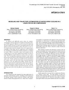
Figure 4 shows the result of the optimization using a Genetic algorithm, where each population member (marked by a blue cross) represents a complete trajectory with reduction values for the two criteria: CO emission Noise footprint (area enclosed by 60 dB contour) These have been normalized with respect to the initial baseline solution trajectory (indicated by a red circle). The criteria are conflicting, since CO emission decreases and noise emissions increases at higher thrust levels. This results in a Pareto front, i.e. a set of optimal solutions, where one criterion cannot be improved without worsening the other one.
Figure 4 Final population solutions relative to baseline solution The illustrated gains with respect to the baseline solution can be achieved when choosing solutions from the final population set, e.g. a 15 % reduction in CO involves an unchanged noise area, while a noise area reduction of 6% is accompanied by a CO reduction of 4 %. Therefore, the maximum noise area reduction is approximately 7.13 km² and the maximum CO reduction is about 0.18 kg.
CEAS 2015 paper no. 252 Page | 6 This work is licensed under the Creative Commons Attribution International License (CC BY). Copyright © 2015 by author(s).
4
ASSESSMENT OF ELECTRIC TAXI SYSTEM
In this example, the object-oriented model framework is used to evaluate the benefits of an on-board electric taxi system fitted to a mid-size, narrow-body commercial aircraft. At present, alternate drive systems are increasingly being studied and developed as a means for environmentally friendly ground operations without use of the main engines. However, while a reduction in fuel consumption and emissions is expected on ground, the additional weight of the related on-board equipment will worsen the flight efficiency. More generally, savings in operating costs can be foreseen due to the smaller fuel consumption on ground and decrease in maintenance costs, especially resulting from reduced use of carbon brakes and reduced running time of the main engines. On the other hand however, these savings may be offset by higher flight costs due to increased aircraft weight as well as other factors such as reduced warm-up time of the main engines (resulting in increased wear) or opportunity costs arising from the reduced available payload as a result of the weight increase. It is clear that the commercial viability and success of this technology stands and falls with a detailed balance of these contrasting effects on a case-to-case basis. This consideration makes the case for pursuing a model-based approach for assessment of this technology. Simulating specific mission programs on a specific aircraft platform and applying appropriate evaluation criteria will help the stakeholders in the decision whether to adopt the electric taxi technology in a development project. Also, if scalable system architectures are available, it is possible to apply optimization strategies to select the most suitable drive system size for the specific needs. The example shown in this paper is based on the work presented in [12] and only focuses on the fuel and emission balance over a defined flight mission. 4.1
Extension and Integration of Aircraft Model
The aircraft model presented in section 2 was used for this study in the 6-DoF variant. Appropriate datasets for geometry, weights, main engine tables and aerodynamics were used to match a mid-size, narrow-body airliner. The model was enhanced with additional parts, as illustrated in Figure 5. Firstly, a landing gear model was added. [25] It represents a complete landing gear with functional models of brakes, steering system, and wheels. The semi-physical tire model used for the wheels has a high level of detail, including force-slip characteristics in both linear and saturated operating regions and rolling resistance as a function of the standing time and rolling speed. The model parameters for the type of aircraft considered were tuned by optimization against measurement data. Conclusively, the landing gear model allows realistic simulation of the ground dynamics. Secondly, a model of ground propulsion system and control electronics was added and linked to the landing gear model. Following the development carried out in [26], the propulsion system was assumed to feature two permanent-magnet synchronous motors, each linked directly to one external wheel of the main landing gears without gearboxes (direct-drive architecture). The motor models contain dynamic equations of an alternate current motor expressed in direct-quadrature axes [27]. The power supply is the Auxiliary Power Unit (APU), possibly enhanced with a dedicated generator. The power electronic controller is represented by one functional model of an inverter for each motor drive. The inverter model supplies the motor drive with the commanded current and draws a current from the electrical network such that the input power is equal to the output power after considering constant, linear, and quadratic inverter losses. A field-oriented control strategy was followed without use of field weakening [27]. CEAS 2015 paper no. 252 Page | 7 This work is licensed under the Creative Commons Attribution International License (CC BY). Copyright © 2015 by author(s).
Figure 5 Aircraft model with electric taxi drive Finally, a functional APU model was added. Based on testing measurements of a real APU at different working points, the curve of fuel consumption over electric power produced by the generator was identified and modelled. Additionally, average emission indices of NOx, CO and HC – i.e. mass of pollutant per mass of fuel burnt – were derived from measurements performed at the Zurich airport [28]. The control architecture includes a flight controller composed of cascaded PID controllers for speed, altitude, heading and roll angle, and a set of PID ground controllers for speed and heading, acting on the brakes and the nose gear steering system, generating the torque command for the electric drive and commanding the engine throttle when the main engines are on during taxi. 4.2
Definition and Simulation of Missions and Trajectories
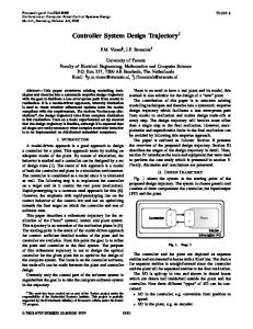
Two different flight missions were defined; they share the same taxi-in, climb, descent, and taxi-out profile while the respective duration of the cruising phase is different (Figure 6). The lengths of the short and long missions are 946 km (approx. 511 NM) respectively 1600 km (approx. 864 NM). The taxi-in and taxi-out profiles are based on realistic operations at the Munich airport (Figure 7). Their durations are 1200 s and 600 s respectively. For each mission, three simulations were carried out for the following architectures: 1. conventional architecture (no electric taxi drive fitted) and conventional taxi with the mainengines 2. A/C with electric taxi drive (including additional weight associated) and conventional APU supply; taxi performed electrically except during the prescribed engine warm-up and cool-down phases 3. A/C with electric taxi drive (including additional weight associated) and zero-emission APU supply (e.g. fuel-cell APU); taxi performed as above. Compared to the second architecture, the third architecture features the same model with an additional weight penalty due to the fuel-cell APU; however, the APU fuel consumption and emissions are CEAS 2015 paper no. 252 Page | 8 This work is licensed under the Creative Commons Attribution International License (CC BY). Copyright © 2015 by author(s).
disregarded in the subsequent evaluation of the simulation data. All simulations were performed with the same payload and an initial fuel quantity (block fuel, alternate and reserve) appropriate for each mission length.
Figure 6 Definition of short (solid line) and long (dotted line) flight missions 4.3
Figure 7 Definition of Munich-airport based taxi-out (red) and taxi-in (blue) trajectories
Simulation Results
As was expected, the fuel consumption results summarized in Table 1 and Table 2 show that Architecture 2 (electric taxi drive, conventional APU) brought a clear benefit over the conventional architecture in the short flight mission, whereas the advantage faded for longer flight missions as a result of the worse flight efficiency. Architecture 3 with a zero-emission APU turned out to be less beneficial in the short flight mission and even detrimental in the long flight mission due to the even larger weight penalty compared to Architecture 2. Note that the fuel for the zero-emission APU was not considered in this scenario. Moreover, the emissions of CO and HC were reduced by values between 26 and 51%, depending on the mission length and the architecture; architecture 3 performed slightly better than architecture 2. NOx emissions remained unchanged instead or were slightly increased. However, the NOx emissions on ground were reduced of up to 75%, showing that a relocation of these emissions away from the airport area takes place. Table 1 Fuel consumption and CO2 emissions in the short flight mission for the three architectures considered Short flight mission (511 NM) Architecture 1 Architecture 2 Taxi-out Fuel [kg] 175 62 Flight Fuel [kg] 4119 4169 Taxi-in Fuel [kg] 91 43 Total mission fuel [kg] 4385 4273 Difference with Architecture 1 –2.6%
Architecture 3 33 4240 28 4300 –1.8%
CEAS 2015 paper no. 252 Page | 9 This work is licensed under the Creative Commons Attribution International License (CC BY). Copyright © 2015 by author(s).
CO2 emission [kg]
13812
13460
13546
Table 2 Fuel consumption and CO2 emissions in the long flight mission for the three architectures considered Long flight mission (864 NM) Architecture 1 Architecture 2 Taxi-out Fuel [kg] 175 62 Flight Fuel [kg] 7019 7110 Taxi-in Fuel [kg] 91 43 Total mission fuel [kg] 7286 7214 Difference with Architecture 1 –1.0% CO2 emission [kg] 22950 22725 5
Architecture 3 33 7238 28 7299 +0.3% 22991
CONCLUSION AND OUTLOOK
This paper has presented a model-based conceptual approach for aircraft-level optimization and assessment. Two application examples have been illustrated that make use of the DLR FlightDynamics library. The examples show the application of dynamic aircraft modelling techniques to an approach trajectory optimization task and the mission-based performance assessment of an electric taxi drive system. In the former case, conflicting optimization criteria result in a Pareto set, with either a reduction in CO emissions of up to 15% or reduction in noise of up to 6%. For the electric taxi drive system, different aircraft-level benefits were shown, depending on the mission length and assumptions on the system architecture. As shown in the two application examples, the DLR FlightDynamics library can, among other things, be used for two important tasks: 1. Optimization of trajectories or systems with respect to aircraft level benefits and 2. Assessment of new technologies. The view of the “entire picture” of any modification of an aircraft system or controller is very important, since many modifications will have an impact on other systems or parts of the mission, especially for highly integrated systems like for MEA. Hence, a physical model of the aircraft behaviour using the FlightDynamics library is an important development tool to obtain aircraft level values. The same methodology can be extended to other system optimisation platforms, like one for the electrical system architecture [3], the thermal system architecture [2], and the landing gear system [25]. Furthermore, the determination and optimization of aircraft-level benefits is key for development of intelligent control functions like an electrical energy management [29] or a thermal management [4]. It should be mentioned that several prerequisites need to be fulfilled to enable the proposed approach. Validated models of the considered aircraft type as well as scalable models of the considered systems are needed for a reliable technology assessment and optimization. However, validated models for existing aircraft types are often available to the stakeholders in the needed level of detail. For new aircraft, multidisciplinary toolchains exist for automatic generation of dynamic models starting from preliminary design data. [30]
CEAS 2015 paper no. 252 Page | 10 This work is licensed under the Creative Commons Attribution International License (CC BY). Copyright © 2015 by author(s).
Also, where multiple partners are involved in early design phases, adequate protection of intellectual properties is required. One solution for this problem is shown in [1], where suitable model exchange methods based on the FMI standard [9] were presented. Conclusively, model-based assessment and optimization methods are expected to play a major role in future aircraft design. These methods allow the assessment of new technologies in a realistic, everyday operational situation and ultimately help stakeholders in the decision whether adopting a new technology in a specific operational case. Finally, an optimized aircraft energy system can be identified using the shown approach. 6
ACKNOWLEDGMENTS
This work has received funding from the European Union’s Seventh Framework Programme (FP7/20072013) for the Clean Sky Joint Technology Initiative under grant agreement n° CSJU-GAN-SGO-2008-001 [23]. BIBLIOGRAPHY
[1] D. Schlabe, M. Sielemann, C. Schallert, D. Zimmer, M. Kuhn, Y. Ji and J. Bals, “Towards a ModelBased Energy System DesignProcess,” in SAE Power Systems Conference 2012, Phoenix, USA, 2012. [2] M. Sielemann, T. Giese, B. Oehler and M. Gräber, “Optimization of an Unconventional Environmental Control System Architecture,” SAE International Journal of Aerospace 4(2), pp. 1263-1275, 18 October 2011. [3] C. Schallert, “A Novel Tool for the Conceptual Design of Aircraft On-Board Power Systems,” in SAE 2007 Aerotech Congress, Los Angeles, USA, 2007. [4] D. Schlabe and J. Lienig, “Model-Based Thermal Management Functions for Aircraft Systems,” in SAE 2014 Aerospace Systems and Technology Conference, Cincinnati, Ohio, USA, 2014. [5] G. Looye, “The New DLR Flight Dynamics Library,” in Proceedings of the 6th International Modelica Conference, Modelica Association, 2008, pp. 193-202. [6] A. Klöckner, G. Looye, R. Müller, R. Kuchar, F. Re and M. Leitner, “Object-Oriented Aircraft Modeling with the DLR FlightDynamics Library,” in 9th AIRTEC 2014 International Congress, Frankfurt, Germany, 2014. [7] P. Fritzson and P. Bunus, “Modelica–A General Object-Oriented Language for Continuous and Discrete-Event System Modeling and Simulation,” in Proceedings of the 35th Annual Simulation Symposium, San Diego, California, USA, 2002. [8] T. Blochwitz, M. Otter, M. Arnold, C. Bausch, C. Clauß, H. Elmqvist, A. Junghanns, J. Mauss, M. Monteiro, T. Neidhold, D. Neumerkel, H. Olsson, J. Peetz and S. Wolf, “The Functional Mockup Interface for Tool independent Exchange of Simulation Models,” in 8th International Modelica Conference, Dresden, Germany, 20.-22 März 2011. [9] The Modelica Association, “Functional Mock-up Interface,” [Online]. Available: https://www.fmistandard.org/. [Accessed 24 8 2015]. [10] D. Vechtel, B. Hauber and G. Looye, “Analysis of a multi-functional high-lift system driven by an active differential gear box,” CEAS Aeronautical Journal, September 2014, Volume 5, Issue 3, pp. 227-238.
CEAS 2015 paper no. 252 Page | 11 This work is licensed under the Creative Commons Attribution International License (CC BY). Copyright © 2015 by author(s).
[11] R. Müller and G. Looye, “A constrained inverse modeling approach for trajectory optimization,” in AIAA Guidance Navigation and Control Conference, Boston, MA, 2013. [12] F. Re, “Assessing Environmental Benefits of Electric Aircraft Taxiing,” SAE Journal of Aerospace, Vols. 5(2):2012, doi:10.4271/2012-01-2218, 2012. [13] A. Klöckner, M. Leitner, D. Schlabe and G. Looye, “Integrated Modelling of an Unmanned HighAltitude Solar-Powered Aircraft for Control Law Design Analysis,” in Advances in Aerospace Guidance, Navigation and Control, Berlin, Heidelberg, Springer, 2013. [14] T. Lombaerts and G. Looye, “Design and flight testing of nonlinear autoflight control laws incorporating direct lift control,” in Second CEAS Specialist Conference on Guidance, Navigation and Control, Delft, The Netherlands, 10.-12. April 2013. [15] G. Looye, An Integrated Approach to Aircraft Modelling and Flight Control Law Design, Technical University Delft: Ph.D. thesis, 2007. [16] G. Looye, “Rapid prototyping using inversion-based control and object-oriented modelling,” Lecture Notes in Control and Information Sciences, 2007. [17] R. Steinhauser, G. Looye and O. Brieger, “Design and Evaluation of Control Laws for the X-31A with Reduced Vertical Tail,” in AIAA-2004-5031, Proc. of AIAA Guidance, Navigation, and Control Conference and Exhibit, Providence, Rhode Island, USA, August 16-19, 2004. [18] G. Looye and H. Joos, “Design of Autoland controller functions with multiobjective optimization,” in Proceedings at the AIAA Guidance, Navigation and Control Conference, 2002. [19] R. Müller, “4D Multiobjective Aircraft Trajectory Optimization with Varying Model Fidelity,” in CEAS EuroGNC Conference, Toulouse, 2015. [20] D. Böhnke, B. Nagel and V. Gollnick, “An Approach to Multi-Fidelty in Conceptual Aircraft Design in Distributed Design Environments,” in IEEE Aerospace Conference, Big Sky, USA, 2011. [21] E. Johnson and A. Calise, “Pseudo-Control Hedging: A New Method For Adaptive Control,” in Advances in Navigation Guidance and Control Technology Workshop, Redstone Arsenal, USA, 2000. [22] “Doc. 29 3rd Edition Report on Standard Method of Computing Noise Contours around Civil Airports, Volume 2: Technical Guide,” European Civil Aviation Conference (ECAC), 2005. [23] Clean Sky Joint Undertaking (CSJU), “The Clean Sky JTI (Joint Technology Initiative),” [Online]. Available: http://www.cleansky.eu. [Accessed 24 August 2015]. [24] H.-D. Joos, J. Bals, G. Looye, K. Schnepper and A. Varga, “A multi-objective optimisation based software environment for control systems design,” in Proc. of 2002 IEEE International Conference on Control Applications and International Symposium on Computer Aided Control Systems Design, Glasgow, IEEE, 2002, pp. 161-176. [25] F. Re, “An Object-oriented Model for Development and Assessment of Green Taxiing Systems,” in 3AF Greener Aviation Conference 2014, Brussels, Belgium, 2014. [26] T. Raminosoa, T. Hamiti, M. Galea and C. Gerada, “Feasibility and Electromagnetic Design of Direct Drive Wheel Actuator for Green Taxiing,” in IEEE Energy Conversion Congress and Exposition. doi: 10.1109/ECCE.2011.6064145, 2011. [27] J. N. Chiasson, Modeling and High Performance Control of Electric Machines, John Wiley & Sons, 2005. [28] E. Fleuti and P. Hofmann, “Aircraft APU Emissions at Zurich Airport,” Unique (Flughafen Zürich AG), 2005. [29] D. Schlabe and D. Zimmer, “Model-Based Energy Management Functions for Aircraft Electrical CEAS 2015 paper no. 252 Page | 12 This work is licensed under the Creative Commons Attribution International License (CC BY). Copyright © 2015 by author(s).
Systems,” in SAE Power Systems Conference 2012, Phoenix, AZ, USA, 2012. [30] T. Kier, G. Looye, M. Scharpenberg and M. Reijerkerk, “Process, methods and tools for flexible aircraft flight dynamics model integration,” in International Forum on Aeroelasticity and Structural Dynamics, Stockholm, Schweden, 2007.
CEAS 2015 paper no. 252 Page | 13 This work is licensed under the Creative Commons Attribution International License (CC BY). Copyright © 2015 by author(s).