MODEL-BASED USER INTERFACE DESIGN. BY EXAMPLE AND BY INTERVIEW. Martin R. Frank. James D. Foley. Graphics, Visualization and Usability Center.
MODEL-BASED USER INTERFACE DESIGN BY EXAMPLE AND BY INTERVIEW Martin R. Frank
James D. Foley
Graphics, Visualization and Usability Center College of Computing, Georgia Institute of Technology Atlanta, Georgia 30332-0280 {martin,foley}@cc.gatech.edu
ABSTRACT
code but they are not accessible from outside the application code. An application model is accessible by the user interface, the application, and external tools at design time and at run time. Examples of model-based user interface management systems (UIMS) are UIDE [1,9] and HUMANOID [4,10,11], which both use high-level object-oriented application models. The original model-based, top-down UIMSs imposed a design methodology on their users which required them to specify a model of the application first which was then used to generate a user interface. Figure 1 illustrates this methodology. This class of UIMS is characterized by the absence of a graphical editor for the user interface so that the designer has little or no control over the end-user interface. The main benefit of this architecture is that the interface is updated automatically if the model changes. However, it has become evident that designers prefer to build visual interfaces in a less formal way.
Model-based user interface design is centered around a description of application objects and operations at a level of abstraction higher than that of code. A good model can be used to support multiple interfaces, help separate interface and application, describe input sequencing in a simple way, check consistency and completeness of the interface, evaluate the interface’s speed-of-use, generate context-specific help and assist in designing the interface. However, designers rarely use computer-supported application modelling today and prefer less formal approaches such as story boards of user interface prototypes. One reason is that available tools often use cryptic languages for the model specification. Another reason is that these tools force the designers to specify the application model before they can start working on the visual interface, which is their main area of expertise. We present the Interactive User Interface Design Environment (Interactive UIDE), a novel framework for concurrent development of the application model and the user interface which combines story-boarding and model-based interface design. We also present Albert, an intelligent component within this framework, which is able to infer an application model from a user interface and from an interview process with the designer.
Phase 1: Write an application model of the intended application in a special-purpose modelling language.
Phase 2: Invoke the automatic user interface generation based on the application model.
KEYWORDS: User Interface Management Systems. Model-
based User Interface Design. INTRODUCTION
Phase 3: Write the application code in a general-purpose programming language.
The paper first discusses the design methodology, application model and usage modes of Interactive UIDE. It then explains the use, architecture and capabilities of Albert. Model-based user interface design uses an application model as an executable specification rather than a paper specification. The key idea is to explicitly represent knowledge that has traditionally been buried in code. For example, objects and operations of an application are represented in
Figure 1. Phases Of Building An Application Using A Pure, Top-Down UIMS (Examples: original UIDE, original HUMANOID) Another class of top-down UIMS gives the designer more control over the user interface by incorporating a graphical user interface editor, shown in the lower left-hand corner of Figure 2. The user interface is generated from the model just as before but the designer can edit the generated interface graphically afterwards. However, note the absence of an arrow back to the first phase, application modelling. After modifying the interface by hand, model changes can no
Cite as: M. Frank and J. Foley. Model-based user interface design by example and by interview. In Proceedings of the ACM Symposium on User Interface Software and Technology, pages 129-137, (Atlanta, Georgia, November 3-5) 1993.
1
longer be propagated automatically to the interface because the manual changes to the interface would be lost. We believe that these systems are still not flexible enough. First, the designer still has to specify an application model for the initial interface generation. Second, designers will be tempted to abandon application modelling once they start editing the generated interface manually because there is no mechanism for regenerating the user interface from a new version of the model without losing manual changes.
Phase 1a: Build the user interface of the intended application using a direct-manipulation tool.
Phase 1b: Write the application model in a special-purpose modelling language.
Phase 2: Write application code in a programming language. Phase 1: Write an application model of the intended application in a modelling language.
Figure 3. Phases Of Building An Application Using Interactive UIDE example, it is not possible to state that a wire is an object which consists of two references to connection points. UofA*’s [7] application model also consists of actions and parameters and is similar in spirit to MIKE’s model. The designer can define application-specific types only in a very limited sense by specifying ranges. For example, an Angle type can be defined as “Angle=[0:360]”. From a programming language perspective, the designer can use predefined simple types like boolean and integer ranges but cannot define classes or records. ITS [12] is a user interface management environment consisting of four layers: user interface primitives like buttons and choice boxes, a rule-based user interface generator, a dialog control component, and application routines. Its main contribution is the encoding of user interface style rules. ITS has no application-level control model but it has an application data model. For example, an employee record can be declared to consist of a name of type string, an address of type address and a manager of type employee. The interface generator can then create a dialog box for displaying such a record. HUMANOID’s [10] model consists of commands, objects, global variables and data flow constraints. Commands have associated inputs (parameters) and preconditions for their applicability. An input describes one parameter of a command by defining its type, a predicate for semantic input validation and other properties. Application objects group commands and simple objects (variables) into a semantically meaningful entity. The data flow constraints are the control element in the model; they specify the dependencies between inputs, variables and objects. Interactive UIDE is based on ideas from the original UIDE [1]. The major differences are the departure from a “model-first” methodology, the concurrent editing of interface and model, and the intelligent component for interactive interface building, model building and consistency checking. The existing components of UIDE such as the textual help generator [9], the animated help generator [8], and the non-interactive user interface generator [2] can still operate within Interactive UIDE. The application modelling language is best explained by an example. We present a
Phase 2: Invoke the automatic user interface generation based on the application model.
Phase 3a: Tune the generated user interface using a direct manipulation interface builder.
Phase 3b: Write application code in a programming language.
Figure 2. Phases Of Building An Application Using a Top-Down UIMS Enhanced With An Interface Builder (Examples: UofA*, MIKE) In our methodology, the designer has the choice of starting a new design with the application model or with the user interface as shown in Figure 3. Visually oriented designers will normally choose to build the actual user interface or story boards first. Albert, the intelligent component within Interactive UIDE, can then infer an application model from the interface and from a dialog with the designer. Alternatively, a designer can provide an application model first and have Albert generate an interface from it; in this way, we support conceptually-oriented designers. In either case, the model and the interface both exist in later stages of the design process, and can both be edited concurrently. In this phase, Albert addresses the synchronization problem of working on two levels of abstraction at the same time by pointing out inconsistencies. THE APPLICATION MODEL
We will now discuss in more detail what an application model is and how our model compares to previous models. This section reviews previous work and explains the structure and use of our model. MIKE [6] is one of the oldest user interface management systems which supports graphical user interfaces. Its application model consists of actions and their parameters. The parameters are of predefined types like String and Point, or application-specific types such as Resistor and Wire for a circuit design application. However, MIKE does not support defining the structure of an application-specific object. For
2
small partial model of a chess application below and discuss its nature and use. Keywords are shown in bold face.
The declarative sequencing through pre- and postconditions facilitates reasoning by external tools. These tools can “understand” the sequencing to an extent which would not be possible with a general-purpose programming language. For example, a help generator can do backchaining to find a sequence of actions which enables an unavailable action by recursively evaluating pre- and postconditions. This sequence can then be presented in textual or animated form.
Boolean gameExists := false Boolean unsavedChanges := false Action New Precondition “!unsavedChanges” Postcondition “gameExists := true” Action Open Precondition “!unsavedChanges” Postcondition “gameExists := true” Action Discard Postcondition “gameExists := false; unsavedChanges := false” Action Save Precondition “gameExists and unsavedChanges” Postcondition “unsavedChanges := false”
MODES OF INTERACTIVE UIDE
At design time, the designer can concurrently edit the user interface, the application model and the “glue” between
Action Quit Precondition “!unsavedChanges”
visually edit
Class ChessPosition Enumeration horizontal: ‘a’..’h’; Enumeration vertical: 1..8;
textually edit
Interface
Glue Designer
Class ChessPiece Variable ChessPosition pos; Action move(ChessPosition p) Postcondition “pos := p; unsavedChanges := true”
textually edit
Model
Class King SubclassOf ChessPiece Class Queen SubclassOf ChessPiece Class Rook SubclassOf ChessPiece Class Bishop SubclassOf ChessPiece Class Knight SubclassOf ChessPiece Class Pawn SubclassOf ChessPiece
Figure 4. Interactive UIDE Design Mode them as shown in Figure 4. The glue is a special-purpose language which specifies the linkage between user interface objects and interaction techniques on one side and application model abstractions on the other side. The user interface is edited using an existing interface building tool, SX/Tools [3], which supports designing custom objects in addition to providing predefined standard objects. The application model and the glue are edited in text editors under control of Interactive UIDE so that switching from design mode to run mode is instantaneous. The designer can then ask Albert, the intelligent component, for advice, for suggestions and for help in inferring an interface or a model. In this mode, the designer reacts to questions and suggestions from Albert which changes the representations based on the designer’s answers. This mode is shown in Figure 5. After the design activity, the designer can instantly switch to run mode. Figure 6 shows the system in run mode. At initialization, Interactive UIDE’s run-time component reads in the textual specifications of the model and the glue, and is linked to application-specific code if such code exists. The user interacts with the application’s user interface which runs as a separate process under control of SX/Tools. Events which are relevant to the application are passed from the interface process to the run-time process which does computation and updates the user interface by sending events back to the user interface process.
The first two elements defined in this model are variables which maintain a subset of the application state, namely if a chess game exists and if it contains unsaved changes. The next elements describe user actions which are accessible from the user interface. Actions are only available if their preconditions apply. In our example, the “New” action is only available if there are no unsaved changes to the current game. The postconditions are assertions which modify the state of the application. For example, the “Discard” action resets the chess application to its initial state. Classes group semantically related data and actions relevant to the user interface. In this model, a ChessPiece is an entity which has a position on the board (data) and which can be moved to a new position (action). Classes can be organized hierarchically. In our example, the King is a particular kind of a ChessPiece. The intent of our application modelling language is to capture the application elements which are relevant to the user interface. It does not provide for multiple inheritance, virtual functions or different inheritance flavors. The objective is not to develop a more complete object-oriented structuring language but to have a sensible compromise between expressiveness and novice understandability.
3
Question 3
1. Read State
Question 2 Question 4
Interface
2. Questions, Suggestions
Question 1
Question 5
Figure 7. Graph Structure Albert Designer
Glue
3. Answers, Choices
Question 1 4. Modify State
select applicable question of highest priority
Model
Figure 5. Interactive UIDE “Interview” Mode
Question 2 Question n
Figure 8. Flat Structure Event Passing
Interact
and application model. We have endorsed this philosophy but there are situations where it is important to ask followup questions to a certain question. Imagine that there are two threads of questions about independent topics. It would be confusing if the presented questions would alternate between the topics. Therefore, we augment the flat structure with a simple mechanism to provide for explicit sequencing of questions by allowing a question to increase the priority of appropriate follow-up questions. This simple mechanism is sufficient for our moderately-sized rule base. We plan to use more sophisticated techniques as the rule base grows.
Runtime Component End User
Interface Read
Glue
Model
Link
Application Code
Figure 6. Interactive UIDE Run Mode Applicability Test T
ALBERT - THE INTELLIGENT COMPONENT WITHIN INTERACTIVE UIDE
T:
+
Albert is the component that can generate questions for building up or for improving the model or the interface. This component needs knowledge about application modelling, user interface design and their relationships. We separate this knowledge into question elements, or knowledge atoms, which encapsulate the information for a single question or suggestion presented to the designer. This knowledge structure is a combination of a rule base and a knowledge base which facilitates system-initiated questions. There are two basic alternatives for the overall organization of these question elements. The first alternative is a graphlike structure, in which a question element explicitly encodes its follow-up questions. This provides for semantically meaningful sequences of related questions. However, the resulting graph structure is hard to understand and maintain. Figure 7 shows this knowledge base structure. The second alternative is a flat structure of questions with no provision for sequencing of related questions as shown in Figure 8. The question elements do not specify which question to ask next, so that the questions can be entered and evaluated independently, greatly simplifying the maintenance of the knowledge base. Questions have applicability tests operating on the context of the current user interface
Parameterized Question Text Q
+ Answers AN and Effects EF
“...” denotes actual text presented to the user. denotes an executable equivalent of the text.
Q: “I found an action A in the application model file which is not connected to a user interface element, so that it can never be invoked.” AN1: “If you want EF1: from the selection box.” AN2: “If you want EF2: OK afterwards.”
Figure 9. Structure Of A Question Element, An Atom Of Albert’s Knowledge Figure 9 shows one of Albert’s question elements. The applicability test determines if this question is relevant in the 4
.
Figure 10: The Complete Framework Of Interactive UIDE
current context. Albert evaluates the applicable atoms and presents the candidate with the highest priority to the designer, using the parameterized question text. It also presents the atom-specific answers in addition to the generic answers available for all question elements such as “ignore question” and “help”. The designer selects one of these answers and the system executes the associated effect. Albert then re-evaluates the atoms and asks the next question.
able to edit the model directly instead of waiting for the system to ask questions. NOVICE USE
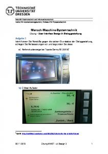
We provide an extended novice example session in which a user interface and an application model for a circuit design application are constructed. The assumption is that the designer has no programming experience and no knowledge about application modelling so far. The designer does not have to edit the textual application model directly, nor does the designer have to understand the nature and use of the model at this point. The designer first constructs the interface using the user interface building component. Figure 10 shows the main window of the combined interface and application model builder in the upper left-hand corner, titled “Interactive UIDE”. The designer has clicked on the “New Interface” button to start a new design and created some elements by dragging from element toolboxes. Figure 10 shows one of the toolboxes on the left (no title) and the user interface design in the center, titled “Circuit Design Application”. The designer then invokes the intelligent component of the system by clicking on the “Albert” button. This brings up two text editors, one for the application model and the other for the glue, both of which are empty so far besides the two lines in the Glue editor which specify which interface and which model are connected by this glue file. These are shown in the lower right-hand corner of Figure 10, titled
USE OF ALBERT
The intelligent component provides support for both novice and expert users. However, the way in which they use Albert differs. Novice users of our system will first build an interface by dragging elements from a palette and customizing them; they then invoke Albert to help them build the application behind the interface. Both of these activities require minimal training. Expert users normally prefer to directly edit the representations instead of going through the interview process but invoke Albert occasionally for design advice and consistency checking. One of the contributions of the framework is the smooth transition from the novice to the expert level. Throughout the interview process, novice designers watch Albert change the user interface and the textual representations in real time in response to their answers. In this way, they learn what information is needed in the model and how answers are transformed into application model knowledge. They are soon
5
“Application Model” and “Model-Interface Glue”. Finally, Albert computes the applicable question with the highest priority and presents it to the designer, shown in the upper right-hand corner, titled “Albert”. In this case, the system has detected that several objects use the same bitmap and queries the designer if they are occurrences of the same concept. The highlighting of the affected user interface elements has proven helpful for designers to understand the context and nature of the question. Let us assume that the designer affirms and provides “NotGate” as the name for the object. The following initial application model is constructed. Class NotGate
The glue representation is also changed to reflect that these three bitmap objects represent instances of the NotGate class. The next questions inquire about the other iconic objects one at a time (“Would you describe this interface object as an instance of a conceptual object?”). The model now looks like this. Class NotGate Class OrGate Class OneSource
Class AndGate Class ZeroSource
Figure 12. Structuring the Model The designer confirms and gives “Element” as a name for that class. The model creates this class and moves the detected common functionality to it.
The system has limited knowledge about typical uses of iconic objects in applications, such as static icons for decoration purposes, icons which represent objects which can be accessed but not moved, and iconic objects which can be created, moved and deleted at run time. The question shown in Figure 11 encodes knowledge of this type. Assume the
Class Element Position pos; Action move (Position newpos) Postcondition “pos := newpos” Class NotGate SubclassOf Element Class AndGate SubclassOf Element Class OrGate SubclassOf Element Class OneSource SubclassOf Element Class ZeroSource SubclassOf Element
We will not further describe the interview process for brevity but it should have become clear how Albert helps novice designers build an application model from a user interface. So far, Albert cannot infer application sequencing so that the pre- and postconditions for sequencing have to be entered in textual form. This shortcoming is discussed in the “Extensions” section. EXPERT USE
Figure 11. Knowledge About Common User Interface Behavior
The previous section illustrated how novices use Albert. Experts will usually invoke Albert as a consultant only and will not rely on its initiative to build up the application model. Albert is redundant in the sense that a user interface and its corresponding model can be built using Interactive UIDE without invoking Albert (using only the design and run modes but not the interview mode). While the intelligent component is redundant, it is not useless for an expert. Few designers are experts in both graphical user interface design and abstract application modelling. Albert offers advice on both of these topics and can be used for consistency checking similar to automated spell checking in text. It can also be used as a “creativity agent”, a source of inspiration for user interface design. Figure 13 is an example of user interface design knowledge.
designer responds by selecting the circuit element objects and pressing the “thumbs up” button. Albert associates a position instance variable and a move action with the affected classes, so that the application model now consists of five classes with the following identical structure. Class X Position pos; Action move (Position newpos) Postcondition “pos := newpos”
The identical structure of these classes triggers another rule intended to help novice users structure their application model, which is shown in Figure 12.
6
port on a higher level. The system should detect that the designer has put in similar information for the last two objects and ask a question at a meta level like “select other objects which have similar behavior and click on the OK button”. It could then fill in model information for these objects at once, consequently reducing the number of repetitive questions. The system could also pose another meta level question when the model inference process has just started, one which offers designers a choice of application model prototypes and asks which one is closest to the application they have in mind. It could then use this model and start asking from there, also reducing the overall number of questions. User Interface Building
Figure 13. Expert Use of Albert
These questions derive a user interface from an application model. This process is often referred to as interface “generation”. We avoid this term because it implies that this is a fully automated process with little or no options for the designer. The by-interview methodology facilitates a more interactive generation process. Albert is able to generate new elements into an existing interface. For example, it can suggest putting a new operation in the same menu where the other operations on this object reside. In this way, user interfaces do not have to be generated completely but can be updated incrementally.
QUESTION CATEGORIES
The Interactive UIDE framework provides for generating many questions and suggestions. We have grouped these questions into seven categories. One category builds up the model based on an existing interface, and, symmetrically, another category infers user interface elements from an application model. Then there are questions which improve a representation contextually or independently and questions which check for consistency. Figure 14 summarizes these categories. Application Model
Glue
User Interface
Modify
Modify
Read
User Interface Building
Read
Modify
Modify
Isolated Model Improvement
Modify
---
---
Isolated Interface Improvement
---
---
Modify
Contextual Model Improvement
Modify
Read
Read
Read
Read
Modify
Modify
Modify
Modify
Application Model Building
Contextual Interface Improvement Consistency Checking
Isolated Model Improvement
In the process of building a model from the interface, there is a point where all the application information from the visual user interface has been exploited but where it is still desirable to improve the model. These questions suggest changes to the application model such as a restructuring of the class hierarchy. Figure 12 shows such a question. Isolated Interface Improvement
It is also possible to refine the existing interface independent of the application model. For example, standard user interface design knowledge can be encoded in our questions so that this knowledge can be accessed and applied by people other than user interface designers. This is similar in spirit to ITS style rules [12] but augmented with the interactive interface to the knowledge. In this way, interface design knowledge is not only automatically applied, but the process is also visible and understandable to the designers so that they learn about interface design themselves while using the system. The question in Figure 13 is of this type. Contextual Model Improvement
These questions suggest model changes based on interface properties. For example, Albert could detect that buttons or menu entries of certain actions are grouped together visually and ask the designer if this represents a semantic grouping that should be captured in the application model.
Figure 14. Question Categories
Contextual Interface Improvement
Application Model Building
Albert could suggest improvements to an interface even if the interface is already complete and consistent with the application model. For example, assume that the actions on a certain type of object are all available in the current interface, but that they reside in different locations. The system
These questions build up a model from the user interface and from the interview process. The model is built by asking questions about the nature of all visible user interface elements one by one. Currently, there are no provisions for sup-
7
could issue a warning about this design and suggest moving them to one location, such as an object-specific popup menu.
are also limited in their expressiveness; they often cannot handle simple parameters. Pure by-example approaches infer a program from a few examples. Myers observed that this contradicts modern software testing principles [5]. According to these principles, a program can never be guaranteed to work correctly if it was tested with a few examples. Consequently, a program inferred from a few examples can also not be guaranteed to implement the desired behavior. The designers cannot be sure of what was inferred unless they read the generated representation. Our system alleviates this problem because the user can directly edit the user interface and application model at any time. Albert operates on these editable representations and changes them in response to the designer’s answers, so that the results of Albert’s activity are guaranteed to be visible and editable.
Consistency Checking
Finally, there is one category of questions concerned with maintaining the consistency of the interface and the application model such as “The application model contains the action Align for class VisualElement which currently cannot be invoked from the interface. Is this intentional?” or “A connection in the glue file refers to a non-existent application action. Do you want me to delete the connection?”. DISCUSSION
We attempt to classify our tool in the context of the established approaches for building user interfaces. Albert encodes domain-specific knowledge in its questions, but it is different from knowledge bases in that the initiative is with the tool rather than with the user. The user invokes Albert but it is the tool that queries the user in order to extract knowledge about design decisions, a system-driven knowledge acquisition process. Albert asks natural language questions, but the questions it asks are canned. It has no capabilities in natural language generation and understanding. The designer provides answers through selecting interface objects and filling out forms. When used to infer an application model, our system starts from a user interface example but it is not a by-example approach such as Peridot [5] in a strict sense because a user interface example alone is not sufficient for inferring a semantic application model. However, our approach still shares a similar philosophy. Examples are inherently easier to understand than abstract concepts, and our system makes use of this fact. Our system is not a with-example approach. In Myers’ and Halbert’s definition [5], programming with example is a generalized macro recording approach, following the philosophy of “do what I did” rather than the “do what I mean” philosophy of by-example programming. Our system does not follow this approach for inferring the structure of an application because this would translate into demonstrating this static structure in a temporal dimension. However, a demonstration of the sequencing aspect of the model, the pre- and postconditions, is possible and discussed in the “Extensions” section. Albert is example-based in the above definition, but not exclusively so. One consequence is that we do not experience the problems often found in systems which are exclusively example-based. These systems suffer from the lack of an editable static representation of the demonstrated behavior. Consequently, selective editing and stepwise improvement become impossible. It is also often frustrating to the users that they cannot directly edit a representation even though they know what they want to specify. Instead, they have to demonstrate the intended behavior, relying on the system to infer the intended modification. The inference found in byexample systems and the recording in with-example systems
EXTENSIONS
Albert is strong in inferring the structure of an application, but it is weak in inferring the sequencing. The designer has to enter pre- and postconditions textually, even when using Albert. This requires proficiency in formal logic which violates Albert’s design goal. Therefore, we are currently investigating ways of deriving pre- and postconditions by easier means. For example, the designer could provide two slightly different interface examples A and B and ask Albert to infer which postcondition would change the interface state from A to B. Or, the designer could draw a visual connection between a button and a popup window so that clicking the button makes the window visible; this could then be translated into the corresponding postcondition for the button and precondition for the window. There could also be support for typical usage of pre- and postconditions. For example, Albert could offer predefined pre- and postcondition templates which cover common usage. We believe that specifying pre- and postconditions by demonstration is the most promising approach. Its strength is that it lets designers describe sequencing declaratively rather than procedurally - they demonstrate how they want the user interface to behave without having to specify the procedural steps that implement this behavior. We are currently extending Albert with demonstrational capabilities. The extended Albert will be able to infer pre- and postconditions from a series of demonstrations. One demonstration consists of a triggering event and pairs of user interface snapshots. The first snapshot of such a pair describes a possible state of the interface before the triggering event. The second snapshot describes the state that the user interface should go to given that the triggering event happened in the context of the first snapshot. The amount of snapshot pairs required to infer a set of pre- and postconditions depends on the complexity of the functionality they describe. We will report on the demonstrational capabilities of the extended Albert in a future paper.
8
CONCLUSION
Application modelling is a highly abstract activity. Its abstract nature is the premier obstacle in bringing its power to a wider audience. The major contribution of Albert is that it does not require novice users to be programmers or user interface management experts to learn building an application model. We also believe that the interactive and concurrent editing and testing of the user interface and its application model in Interactive UIDE will speed up application development, and that leaving it up to the designers if they prefer starting a new project with the user interface or the application model (Figure 15) will attract more visually-oriented designers to application modelling.
Interface
2 Time Interface
Model
3
1 2 3
[4]
Luo, P., P. Szekely and R. Neches, Management Of Interface Design in HUMANOID, Proceedings of INTERCHI’93, ACM Conference on Human Factors in Computing Systems, Apr. 1993, pp. 107-114.
[5]
Myers, B., Creating User Interfaces By Demonstration, Academic Press, Boston, 1988.
[6]
Olsen, D., MIKE: The Menu Interaction Kontrol Environment, ACM Transactions on Graphics, Vol. 5, No. 1, Oct. 1986, pp. 318-344.
[7]
Singh, G. and M. Green, A High-Level User Interface Management System, Proceedings of CHI’89, ACM Conference on Human Factors in Computing Systems, May 1989, pp. 133-138.
[8]
Sukaviriya, P. and J. Foley, Coupling a User Interface Framework with Automatic Generation of ContextSensitive Animated Help, Proceedings of UIST’90, ACM Symposium on User Interface Software and Technology, Oct. 1990, pp. 152-166.
[9]
Sukaviriya, P., J. Foley and T. Griffith, A Second Generation User Interface Design Environment: The Model And The Runtime Architecture, Proceedings of INTERCHI’93, ACM Conference on Human Factors in Computing Systems, Apr. 1993, pp. 375382.
Model
1
3 Interface
Kühme, T. and M. Schneider-Hufschmidt, SX/Tools An Open Design Environment for Adaptable Multimedia User Interfaces, Computer Graphics Forum, 11(3), Sept. 1992, pp. 93-105.
Model-First Methodology
Interface-First Methodology
Model
[3]
Model
[10] Szekely, P., P. Luo and R. Neches, Facilitating the Exploration of Interface Design Alternatives: The HUMANOID Model of Interface Design, Proceedings of CHI’92, ACM Conference on Human Factors in Computing Systems, May 1992, pp. 507515.
Interface
Computer-Supported Application Model Inference User Interface Generation Computer-Supported Concurrent Development
[11] Szekely, P., P. Luo and R. Neches, Beyond Interface Builders: Model-Based Interface Tools, Proceedings of INTERCHI’93, ACM Conference on Human Factors in Computing Systems, Apr. 1993, pp. 383390.
Figure 15. Interactive UIDE’ Support For Both Top-Down And Bottom-Up Design ACKNOWLEDGEMENTS
We gratefully acknowledge the many helpful suggestions from Christie Gerlach, Thomas Kühme, Anton Spaans, Piyawadee Sukaviriya and the (anonymous) referees. We thank Sun Microsystems and Siemens for partial funding of this project.
[12] Wiecha, C. and S. Boies, Generating User Interfaces: Principles and Use of ITS Style Rules, Proceedings of UIST’90, ACM Symposium on User Interface Software and Technology, Oct. 1990, pp. 21-30.
REFERENCES
[1]
Foley, J., W. Kim, S. Kovacevic, and K. Murray, Defining Interfaces at a High Level of Abstraction, IEEE Software, 6(1), Jan. 1989, pp. 25-32.
[2]
Kim, W. and J. Foley, DON: User Interface Presentation Design Assistant, Proceedings of UIST’90, ACM Symposium on User Interface Software and Technology, Oct. 1990, pp. 10-20.
9