Based on a proposed space vector based selective harmonic .... See http://www.ieee.org/publications_standards/publications/rights/index.html for more ...
This article has been accepted for publication in a future issue of this journal, but has not been fully edited. Content may change prior to final publication. Citation information: DOI 10.1109/TPEL.2016.2616358, IEEE Transactions on Power Electronics
> REPLACE THIS LINE WITH YOUR PAPER IDENTIFICATION NUMBER (DOUBLE-CLICK HERE TO EDIT)
REPLACE THIS LINE WITH YOUR PAPER IDENTIFICATION NUMBER (DOUBLE-CLICK HERE TO EDIT) < capacitor current, which also leads to the degraded dynamic performance of the CSC [3]. Furthermore, no matter in grid-connected or motor-drive applications, the load normally presents inductive behavior. The inductor in the load constructs an LC resonance tank with the three-phase capacitor. The LC resonance can be easily excited during transients, which possibly causes overcurrent and overvoltage [4, 5]. Generally, implementing a closed-loop control scheme for power converters using SHE-PWM is not a trivial task, especially for the CSC. Recently, model predictive control (MPC) has emerged as a promising alternative to govern power converters. MPC based approach generally provides better dynamic responses compared to traditional controls [6]. In previous literature, MPC has been introduced for two-level and multilevel VSCs [7, 8] in grid-connected and motor-drive applications [9, 10]. MPCs for current source inverter (CSI) with three-phase RL load are proposed in [11, 12]. In [13], MPC for CSR is presented, in which dc current regulation and reactive power control are realized by an associated cost function. However, the existing schemes are just suitable for low power CSC with high switching frequency. Besides, the resulting switching actuations during every sampling interval remain unknown, which leads to variable switching frequencies in steady state. Up to now, for MV application, MPCs with very low switching frequency have been proposed, either. In [14], model predictive direct torque control (MPDTC) is proposed for MV motor drives, through which both torque and stator flux magnitude are kept in their respective bonds, and the switching frequency can be reduced compared to standard DTC. Whereas, since the torque and flux are directly regulated, the distortion of stator current is not taken into consideration in this scheme. To minimize the THD of the stator current for a given switching frequency, model predictive pulse pattern control (MP3C) is proposed in [15]. A prediction horizon of multi-steps in time is used, and the switching instants of the pulse pattern are shifted, such that a stator flux error is corrected within this horizon. From the end of the horizon onwards, offline calculated optimal pulse pattern (OPP) is assumed to be used in steady state. Though MP3C can improve dynamic performance, and maintain OPP output in steady state, the method requires multistep prediction, which complicates the realization, and increases the calculation burden. Similarly, multistep MPC has been shown to have the potential to achieve a performance similar to that of optimized voltage patterns in [16]. However, the main concern of multistep methods still focuses on the higher calculation requirement, compared to one-step approach. MPC, generating an SHE-like pattern has been proposed in [17]. This scheme is based on a sliding discrete Fourier transform (SDFT) that calculates voltage harmonics in real time, then it uses this information to mitigate unwanted harmonics. This method still involves huge calculation, since a large sampling window (one fundamental period at least) is used to properly calculate these harmonics. Besides, dynamic performance is not considered in this method. A SHE-MPC has been proposed in [18], through which the output voltage of multilevel VSC follows
2
SHE-PWM pattern in steady state, and the VSC generates optimally selected output voltage states by MPC during transients to ensure improved dynamic response. However, there are mainly two drawbacks existing in this scheme. One is that due to a constant sampling frequency used in it, quantization effect is introduced, and leads to the error between the practically applied switching angles and the optimally calculated ones, which degrades its low-order harmonic elimination performance. Since a weighting factor is used in the cost function to associate two variables with different units (predicted load currents and SHE base output voltage states) together, the tuning of weighting factor has a direct influence on the final output performance. In this work, a model predictive switching pattern control (MPSPC) for the CSC is presented, which eliminates quantization errors in steady state, and avoids the use of weighting factor in comparison with the state-of-the-art schemes. MPSPC is realized based on a proposed space vector representation of SHE-PWM pattern for the CSC. During a constant sampling interval, a saw-tooth carrier is applied to generate SHE-PWM waveform through a quasi-modulation process. Besides, at every sampling instant, according to the selected space vectors and calculated dwell time for SHE-PWM pattern, the load current at the end of this sampling interval can be predicted. Then, the error between the load current reference and its predicted value can be obtained. If the error is smaller than a predefined maximum limitation, the output PWM current just follows the SHE-PWM pattern, which means that SHE-PWM can satisfy the requirement of output performance. On the other hand, with the error larger than the maximum limitation, which usually appears during the transient process, the applied output current vector during this sampling interval is optimally selected through an MPC method, which achieves improved dynamic performance with shorter settling time and suppressed LC resonance. At the next sampling instant, this procedure is repeated with new measurements to keep the load current tracking its reference. The proposed scheme has been verified based on different SHE-PWM patterns for the CSC. Compared to the SHE-PWM modulator in tradition control, MPSPC improves the dynamic performance, and preserves the SHE-PWM waveform in the steady state. Compared to the state-of-the-art MPC approaches, the benefits of MPSPC are threefold. First, with a saw-tooth carrier based quasi-modulation process in MPSPC, there is no quantization error, as mentioned in [18], anymore, which totally maintains the selective low-order harmonic elimination performance. Second, there is no weighting factor selection issue, as in [14, 18], since only predicted load current and its reference appear in the cost function. Though a maximum limitation of load current error needs to be defined, it has more significant physical meaning, and is easier to be selected, in comparison with a weighting factor. Last but not least, MPSPC only uses a one-step or horizon-one prediction, not like the multistep predictions in [14-16]. The one-step prediction leads to a simple structure, and reduces the complexity of the proposed scheme. With MPSPC, the switching frequency can be kept
0885-8993 (c) 2016 IEEE. Personal use is permitted, but republication/redistribution requires IEEE permission. See http://www.ieee.org/publications_standards/publications/rights/index.html for more information.
This article has been accepted for publication in a future issue of this journal, but has not been fully edited. Content may change prior to final publication. Citation information: DOI 10.1109/TPEL.2016.2616358, IEEE Transactions on Power Electronics
> REPLACE THIS LINE WITH YOUR PAPER IDENTIFICATION NUMBER (DOUBLE-CLICK HERE TO EDIT) < iw
3
8
2
12
0 3 1 12 20 3 2 6 0
6
0
3
2
2 3 5 6
7 6 4 3 3 2 5 4 11 6
0
2
a iw 1
0
24
1
24
3 3 12 1
8
0
0
3 1 3 2 20 6 0
2 3
0
6
2
3
a 2 3 5 6
7 6 4 3 3 2 5 4 11 6
2
12
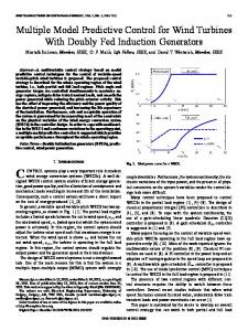
Fig. 2. SHE-PWM waveforms: (a) six pulses per half-cycle and (b) eight pulses per half-cycle.
24
constant and at a very low value in steady state. During transients, the CSC is governed by MPC to achieve improved dynamic performance, which achieves superior output performance for MV applications.
24
This paper is organized as follows. Section II summarizes the background of SHE-PWM for the CSC, while Section III proposes a space vector based SHE as the foundation of MPSPC. Section IV describes the details of the proposed scheme. Simulation results using in a high power MV CSC (1 MW/4160 V/17.3 A) and experimental results in a low power prototype (3 kW/208 V/8.33 A) are presented in Section V and VI, respectively. Finally, some conclusions are drawn in Section VII.
SHE-PWM pattern should meet switching constraints of the CSC, that is at any instant of time there are only two switching devices conducting, one in the top half and the other in the bottom half of the bridge. Normally there are two commonly used SHE-PWM pattern for the CSC, namely six pulses per half cycle for output frequency around 60 Hz, and eight pulses per half cycle for output frequency around 50 Hz. With these two kinds of PWM patterns, the switching frequencies of switching devices in the CSC are just about 360 Hz or 400 Hz [1]. Fig. 2 shows typical SHE-PWM waveforms for the CSC. In Fig. 2 (a), there are six switching angles in the first 2 period of the six-pulse waveform. However, only three out of the six angles, 1 , 2 , and 0 , are independent, which can be used to eliminate two harmonics and in the meanwhile provide and adjustable modulation index. Similarly, the waveform with eight pulses per half cycle is depicted in Fig. 2 (b), in which there are only four independent angles, 1 , 2 , 3 , and 0 . With these four angles, three selected harmonics can be eliminated, and modulation index can be adjusted, either. The PWM current waveform in Fig. 2 can be expressed in Fourier series as n 1
where
n
sin n t
(1)
3 0
2
0
1
12 1
8 0
2
3
0
0.1 0.2 0.3 0.4 0.5 0.6 0.7 0.8 0.9 1.0 ma
b
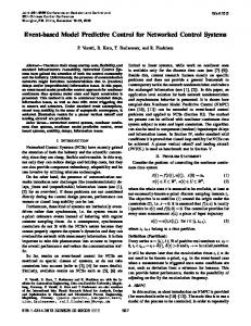
Fig. 3. Independent angle solutions for SHE (a) six pulse per half cycle and (b) eight pulse per half cycle.
an
4
2 0 w
i t sin n t d n t
(2)
Here six-pulse waveform is used as an example. In order to eliminate two dominant low-order harmonics such as the 5th and 7th, and adjust modulation index, the following system of equations is defined as
F1 cos 51 cos 5 2 cos 5 6 0 cos 5 3 2 cos 5 3 cos 5 2 0 1 0 F cos 11 cos 11 cos 11 6 0 cos 11 3 2 2 1 2 cos 11 3 1 cos 11 2 0 0 F3 4 [cos 1 cos 2 cos 6 0 cos 3 2 cos 3 1 cos 2 0 ] ma 0
II. SHE-PWM FOR CSC
a
0
8
b
iw t
2
0.1 0.2 0.3 0.4 0.5 0.6 0.7 0.8 0.9 1.0 ma
(3)
where m a is the modulation index, given by Iˆ ma w1 (4) I dc in which Iˆ is the peak fundamental-frequency component of w1
the PWM current, and I dc is the average dc current. Similarly, for an eight-pulse waveform with four independent angles, four equations can also be established to eliminate three dominant harmonics, such as the 5th, 7th, and 11th, and adjust modulation index. The nonlinear and transcendental equation of (3) can be solved by a number of numerical methods [19], one of which is the Newton-Raphson iteration algorithm. At various modulation indexes, independent angles for six- and eight-pulse waveforms have been calculated and the solutions are shown in Fig. 3. In Fig. 3, no matter for six-pulse or eight-pulse waveform, the maximum modulation index is around 1.02, at which 0 becomes zero and the notch in the center of the half-cycle PWM waveform disappears. For a given value of 1 , 2 , and 0 ,
0885-8993 (c) 2016 IEEE. Personal use is permitted, but republication/redistribution requires IEEE permission. See http://www.ieee.org/publications_standards/publications/rights/index.html for more information.
This article has been accepted for publication in a future issue of this journal, but has not been fully edited. Content may change prior to final publication. Citation information: DOI 10.1109/TPEL.2016.2616358, IEEE Transactions on Power Electronics
> REPLACE THIS LINE WITH YOUR PAPER IDENTIFICATION NUMBER (DOUBLE-CLICK HERE TO EDIT) < Case I : m a 0.83 1 0
g1
Case I : ma 0.98 1 0
g1
BP2
BP1
1
t
0
g4
1
1
t
iwa
0
3 1 2 0 3 2 6 0
t
3 3
0
1 2
3
1
20
a
Case II : ma 0.83 1 0 BP1
BP2
BP3
BP4
BP1
BP1
1
Case II : 0.89 REPLACE THIS LINE WITH YOUR PAPER IDENTIFICATION NUMBER (DOUBLE-CLICK HERE TO EDIT)
REPLACE THIS LINE WITH YOUR PAPER IDENTIFICATION NUMBER (DOUBLE-CLICK HERE TO EDIT)
REPLACE THIS LINE WITH YOUR PAPER IDENTIFICATION NUMBER (DOUBLE-CLICK HERE TO EDIT) < control schemes, iwop is not synthesized based on SVM, since a high sampling frequency in MPSPC would lead to a large number of commutations during transients, which is not suitable to high power applications. To reduce the possible commutations, the space vector, which is the closest to iwop , would be selected and applied during the whole sampling interval. In [20], this method is called low-complexity MPC, which preserves the advantage of conventional MPC, and simplifies the realization. According to the six active-state space vectors, the space vector domain can be divided into six segments, as Fig. 11 shows.
C. Delay Compensation In ideal cases, the calculated optimal output current vector will be applied during the whole kth sampling interval. However, in a real implementation, calculation burden introduces a considerable time delay in the actuation, which will deteriorate the performance of MPSPC. A well-known two-step prediction method is used for delay compensation. The state variables at (k+1)th instant need to be estimated based on the optimal output current vector selected for kth sampling interval. After that, the load current vector at (k+2)th instant will be predicted to optimally select the optimal output current vector for (k+1) th sampling interval. At the time, the load current reference vector should be shifted one step forward. Finally, the cost function can be modified as ˆ i ref i p k 2
J k 1
ˆ i ref
(16)
ˆ
where i ref is the load current reference vector for the (k+2)th instant, and can be given as ˆ i ref i ref e jTs (17) in which is the angular rotating speed of the synchronous frame. V. SIMULATION RESULTS The simulation results for a 1 MW/4160 V CSC are presented in this section. The parameters used in simulation are listed in Table III. The proposed MPSPC with both six-pulse and eight-pulse SHE-PWM pattern are verified in simulation. The dc current is generated by an ideal dc current source, of which the value is kept at the rated dc current of 196 A. The sampling frequency of 10 kHz, meaning sampling interval of 100 μs is used for the proposed MPSHEC. The value of J max is selected as 15%. A. Steady State Performance Table IV lists the steady state performance of proposed MPSPC at the operating condition of idref equal to 196 A and ref q
i
equal to 0 A. For comparison, the results of traditional
9
TABLE III PARAMETERS IN SIMULATION AND EXPERIMENTS Item Simulation Experiment Rated power 1 MW 3 kW Rated voltage 4160 V 208 V Capacitor 0.5 pu 0.6304 pu Filter inductor 0.3 pu 0.2614 pu Load resistor 0.3 pu 0.3467 pu TABLE IV SIMULATED STEADY STATE PERFORMANCE SHE Harmonic order Control scheme PATTERN 5th 7th 11th Six-pulse 2.50% 4.06% 58.4% Traditional SHE-MPC Eight-pulse 1.66% 1.98% 3.06% Six-pulse 0.06% 0.27% 57.0% MPSPC Eight-pulse 0.28% 0.06% 0.16%
13th 21.3% 36.3% 22.5% 36.8%
SHE-MPC with quantization error are also provided, in which the sampling frequency is still 10 kHz. It can be found that with traditional SHE-MPC the unwanted low-order harmonics, no matter 5th and 7th for the six-pulse waveform or 5th, 7th, and 11th for eight-pulse waveform, cannot be completely eliminated due to the effect of quantization errors. Whereas, MPSHEC totally completes the objectives of low-order harmonic elimination. Though a constant sampling frequency is used in MPSHEC, there is no compromise, caused by quantization error, between pre-calculated optimal switching angles and finally applied ones. B. Transient Responses Compared to only space vector based SHE without prediction process, the proposed MPSPC improves dynamic performance. For comparison, transient responses with only space vector based SHE are provided, either. In Fig. 13, the output frequency of the CSC is 60 Hz, and six-pulse SHE waveform is used. At time t of 0.1 s, isdref is dropped from 196 A ref to only 39.3 A. isq is kept at 0 during the whole process.
During the transient process, the settling time,
Tsettle , of load
current is measured with the response stay in a range of 5% of the rated value. It can be observed from Fig. 13 (a) that the transient responses of load currents are very sluggish, and
Tsettle is equal to 23 ms when with only space vector based SHE. Since capacitor and filter inductor construct an LC resonant tank, significant resonance can be observed in load currents, especially in dq-axis components. With MPSPC, during transients, since the calculated cost function can be easily higher than
J max , the PWM pattern of the CSC is
naturally changed from SHE waveform to optimally selected space vectors by MPC. With this mechanism, the load currents fast track their references, and
Tsettle is reduced to only 14 ms.
Moreover, the LC resonance is somewhat suppressed, since the calculated optimal output current reference forces load currents to follow their references. After transients, it can be found that output PWM pattern returns to SHE waveform due to the reduced cost function value in steady state. Hence, without the
0885-8993 (c) 2016 IEEE. Personal use is permitted, but republication/redistribution requires IEEE permission. See http://www.ieee.org/publications_standards/publications/rights/index.html for more information.
This article has been accepted for publication in a future issue of this journal, but has not been fully edited. Content may change prior to final publication. Citation information: DOI 10.1109/TPEL.2016.2616358, IEEE Transactions on Power Electronics
> REPLACE THIS LINE WITH YOUR PAPER IDENTIFICATION NUMBER (DOUBLE-CLICK HERE TO EDIT)
REPLACE THIS LINE WITH YOUR PAPER IDENTIFICATION NUMBER (DOUBLE-CLICK HERE TO EDIT) < ref
11.8 A and iq equal to 0 A. Fig. 15 shows phase A load current, output PWM current, and its spectrum diagram of traditional SHE-MPC and MPSPC. Due to quantization error, the output PWM current of traditional SHE-MPC contains obvious low-order harmonics. Moreover, as can be observed in Fig. 15 (b), the quantization effect makes some very small pulses missed from the eight-pulse waveform, which leads to only six or seven pulses per half cycle. On the other hand, MPSPC achieves better performance on low-order harmonic elimination than traditional SHE-MPC, no matter with six-pulse or eight-pulse SHE-PWM pattern. The details on the low-order harmonic contents are listed in Table V. With proposed MPSPC, the unwanted low-order harmonics can be mitigated to very small values. It can be found that the harmonic contents in Table V are higher than the results presented in Table VI. The reason is that the dc current used in experiments is not ideal, and contains some ripples, which causes some compromises on low-order harmonic elimination. B. Transient Response Fig. 16 shows the experimental transient responses with the six-pulse SHE-PWM waveform. The output frequency is 60 ref
limitation of tracking error needs to be selected to ensure the natural transition between SHE-PWM pattern and optimal output current vector selected by MPC during transients, it owns more significant physical meaning in comparison with a weighting factor. 3) On-Step Prediction: MPSPC only uses a one-step or horizon-one prediction, which leads to a simpler structure, and reduces the complexity, compared to existing multi-step schemes. REFERENCES [1] [2]
[3]
[4]
[5]
Hz, and id suddenly drops from 11.8 A to 2.36 A. From top to bottom, phase A output PWM current, load current, dq-axe load current components, and their respective references are shown. With only space vector based SHE, significant resonance can be observed in the waveforms of id and iq , as Fig. 16 (a)
[6]
shows. The settling time is equal to 21 ms. In Fig. 16 (b), with MPSPC, id changes from 11.8 A to 2.36 A faster, and the resonance in load current is suppressed, with the decrease of the settling time to 13 ms. The transition from SHE-PWM to MPC can be found from the output PWM current during the transient. After the transient, the output PWM current is governed by SHE-PWM again.
[8]
VII. CONCLUSION In this work, MPSPC scheme based on a proposed space-vector-based SHE method is presented, which achieves low-order harmonics elimination in steady state, and improves dynamic performance. In MPSPC, the predictive controller modifies the optimal output current vector during transients. Regarding the steady state, MPSPC is able to resemble the optimized PWM current pattern, which follows the SHE-PWM pattern. As evidenced by the results, compared to the state-of-the-art schemes, the proposed scheme offers three major advantages: 1) No Quantization Error: A space vector based SHE generation method is proposed as the foundation of MPSPC, which eliminates the quantization effect introduced by a constant sampling frequency for MPC. Without quantization error, the low-order harmonics elimination based on pre-calculated optimal switching angles can be thoroughly completed. 2) No Weighting Factor: Another benefit offered by MPSPC is that there is no weighting factor used in it. Though a maximum
11
[7]
[9]
[10]
[11]
[12]
[13]
[14]
[15]
[16]
[17]
[18]
B. Wu, High-power converters and AC drives: John Wiley & Sons, 2006. B. Wu, J. Pontt, J. Rodriguez, S. Bernet, and S. Kouro, "Current-Source Converter and Cycloconverter Topologies for Industrial Medium-Voltage Drives," Industrial Electronics, IEEE Transactions on, vol. 55, pp. 2786-2797, 2008. Z. Wang, B. Wu, D. Xu, and N. R. Zargari, "Hybrid PWM for High-Power Current-Source-Inverter-Fed Drives With Low Switching Frequency," Power Electronics, IEEE Transactions on, vol. 26, pp. 1754-1764, 2011. J. C. Wiseman and B. Wu, "Active damping control of a high-power PWM current-source rectifier for line-current THD reduction," Industrial Electronics, IEEE Transactions on, vol. 52, pp. 758-764, 2005. Y. W. Li, B. Wu, N. R. Zargari, J. C. Wiseman, and D. Xu, "Damping of PWM Current-Source Rectifier Using a Hybrid Combination Approach," Power Electronics, IEEE Transactions on, vol. 22, pp. 1383-1393, 2007. S. Kouro, P. Cortes, R. Vargas, U. Ammann, and J. Rodriguez, "Model Predictive Control - A Simple and Powerful Method to Control Power Converters," Industrial Electronics, IEEE Transactions on, vol. 56, pp. 1826-1838, 2009. S. Kouro, M. A. Perez, J. Rodriguez, A. M. Llor, and H. A. Young, "Model Predictive Control: MPC's Role in the Evolution of Power Electronics," IEEE Industrial Electronics Magazine, vol. 9, pp. 8-21, 2015. V. Yaramasu, B. Wu, and J. Chen, "Model-Predictive Control of Grid-Tied Four-Level Diode-Clamped Inverters for High-Power Wind Energy Conversion Systems," Power Electronics, IEEE Transactions on, vol. 29, pp. 2861-2873, 2014. Y. C. Zhang and H. T. Yang, "Model Predictive Torque Control of Induction Motor Drives With Optimal Duty Cycle Control," Power Electronics, IEEE Transactions on, vol. 29, pp. 6593-6603, 2014. Y. C. Zhang and H. T. Yang, "Generalized Two-Vector-Based Model-Predictive Torque Control of Induction Motor Drives," Power Electronics, IEEE Transactions on, vol. 30, pp. 3818-3829, 2015. M. Rivera, S. Kouro, J. Rodriguez, B. Wu, and J. Espinoza, "Predictive control of a current source converter operating with low switching frequency," in IECON 2012 - 38th Annual Conference on IEEE Industrial Electronics Society, 2012, pp. 674-679. P. Zavala, M. Rivera, S. Kouro, J. Rodriguez, B. Wu, V. Yaramasu, et al., "Predictive control of a current source rectifier with imposed sinusoidal input currents," in Industrial Electronics Society, IECON 2013 - 39th Annual Conference of the IEEE, 2013, pp. 5842-5847. P. Correa, J. Rodriguez, I. Lizama, and D. Andler, "A Predictive Control Scheme for Current-Source Rectifiers," Industrial Electronics, IEEE Transactions on, vol. 56, pp. 1813-1815, 2009. T. Geyer, G. Papafotiou, and M. Morari, "Model Predictive Direct Torque Control-Part I: Concept, Algorithm, and Analysis," Industrial Electronics, IEEE Transactions on, vol. 56, pp. 1894-1905, 2009. T. Geyer, N. Oikonomou, G. Papafotiou, and F. Kieferndorf, "Model predictive pulse pattern control," in Energy Conversion Congress and Exposition (ECCE), 2011 IEEE, 2011, pp. 3306-3313. T. Geyer and D. E. Quevedo, "Performance of Multistep Finite Control Set Model Predictive Control for Power Electronics," Power Electronics, IEEE Transactions on, vol. 30, pp. 1633-1644, 2015. S. Kouro, B. L. Rocca, P. Cortes, S. Alepuz, B. Wu, and J. Rodriguez, "Predictive control based selective harmonic elimination with low switching frequency for multilevel converters," in 2009 IEEE Energy Conversion Congress and Exposition, 2009, pp. 3130-3136. R. Aguilera, P. Acuna, P. Lezana, G. Konstantinou, B. Wu, S. Bernet, et al., "Selective Harmonic Elimination Model Predictive Control for
0885-8993 (c) 2016 IEEE. Personal use is permitted, but republication/redistribution requires IEEE permission. See http://www.ieee.org/publications_standards/publications/rights/index.html for more information.
This article has been accepted for publication in a future issue of this journal, but has not been fully edited. Content may change prior to final publication. Citation information: DOI 10.1109/TPEL.2016.2616358, IEEE Transactions on Power Electronics
> REPLACE THIS LINE WITH YOUR PAPER IDENTIFICATION NUMBER (DOUBLE-CLICK HERE TO EDIT) < Multilevel Power Converters," IEEE Transactions on Power Electronics, vol. PP, pp. 1-1, 2016. [19] J. Napoles, J. I. Leon, R. Portillo, L. G. Franquelo, and M. A. Aguirre, "Selective Harmonic Mitigation Technique for High-Power Converters," IEEE Transactions on Industrial Electronics, vol. 57, pp. 2315-2323, 2010. [20] Y. C. Zhang and W. Xie, "Low Complexity Model Predictive Control Single Vector-Based Approach," Power Electronics, IEEE Transactions on, vol. 29, pp. 5532-5541, 2014.
12
Pablo Acuna (M’12) received the B.Sc. in Electronics Engineering, the Electronics Engineering Professional degree, and the Ph.D. degrees in Electrical Engineering from the University of Concepcion, Chile, in 2004, 2007, and 2013 respectively. He is currently Research Associate at the school of Electrical Engineering and Telecommunications, University of New South Wales, Australia. His research interests include electrical power conversion systems and its applications to industry, transportation and utility.
Hang Gao received the B.Sc and M.A.Sc degrees in electrical engineering from Hefei University of Technology (HFUT), Anhui, China, respectively in 2011 and 2014. He is currently working towards the Ph.D. degree in electrical and computer engineering at Ryerson University, Toronto, ON, Canada. His research interests include high-power converter topologies, model predictive control, and ac motor drives. Mr. Gao is a recipient of Ontario Trillium Scholarship (OTS), for pursuing his Ph. D. study in power electronics. Bin Wu (S’89-M’92-SM’99-F’08) received his M.A.Sc. and Ph.D. degrees in electrical and computer engineering from the University of Toronto, Canada in 1989 and 1993, respectively. He joined Ryerson University in 1993, where he is currently a Professor and Senior NSERC/Rockwell Automation Industrial Research Chair in Power Electronics and Electric Drives. Dr. Wu has published more than 350 technical papers, authored/coauthored two Wiley-IEEE Press books, and holds more than 30 granted/pending US/European patents in the area of power conversion, medium voltage drives, and renewable energy systems. Dr. Wu received the Gold Medal of the Governor General of Canada in 1993, Premier’s Research Excellence Award in 2001, NSERC Synergy Award for Innovation in 2002, Ryerson Distinguished Scholar Award and Professional Engineers Ontario (PEO) Engineering Excellence Medal in 2014. He is a fellow of Engineering Institute of Canada (EIC) and Canadian Academy of Engineering (CAE).
Dewei(David) Xu (S’99–M’01) received the B.Sc, M.A.Sc, and Ph.D. degree in electrical engineering from Tsinghua University, Bejing, China, respectively in 1996, 1998, and 2001. He has been working in Ryerson University, Toronto, Ontario since 2001, where he is currently Professor. His research interests include renewable energy system, high power converters, electric motor drives and advanced digital control for power electronics.
Ricardo P. Aguilera (S’01–M’12) received his M.Sc. degree in Electronics Engineering from the Universidad Tecnica Federico Santa Maria (UTFSM), Chile, 2007, and Ph.D. degree in Electrical Engineering from The University of Newcastle (UoN), Australia, 2012. From 2012 to 2013, he was a Research Academic at UoN, where he was part of the Centre for Complex Dynamic Systems and Control. From 2014 to 2016, he was a Senior Research Associate at The University of New South Wales (UNSW), Australia, where he was part of the Australian Energy Research Institute (AERI). Since 2016, he is with the School of Electrical, Mechanical and Mechatronic Systems, at The University of Technology Sydney (UTS), Australia, where he currently holds a Lecturer position. His main research interests include power electronics, and theoretical and practical aspects on model predictive control.
0885-8993 (c) 2016 IEEE. Personal use is permitted, but republication/redistribution requires IEEE permission. See http://www.ieee.org/publications_standards/publications/rights/index.html for more information.