Adresse: Humboldt-Universit t zu Berlin. Institut f r Informatik. Unter den Linden 6, D-10099 Berlin. P. Starke ..... U. -e le m . ZE dummy. UE2- Dummy. EA1 Dummy. OR_AN=0. (p800) ..... mentation einer mikrorechnergest tzten Bahn bergangs-.
Modeling and formal veri�cation of a modular level-crossing controller design H.-M. Hanisch
Adresse: �Otto - von - Guericke� Universität Magdeburg, Institut für Automatisierungstechnik, PF 4120 D-39019 Magdeburg T. Pannier
Adresse: Siemens AG Verkehrstechnik Ackerstraÿe 22 D-38126 Braunschweig D. Peter
Adresse: Siemens AG Verkehrstechnik Ackerstraÿe 22 D-38126 Braunschweig S. Roch
Adresse: Humboldt-Universität zu Berlin Institut für Informatik Unter den Linden 6, D-10099 Berlin P. Starke
Adresse: Humboldt-Universität zu Berlin Institut für Informatik Unter den Linden 6, D-10099 Berlin
We deal here with that part of the overall control system which is actually responsible for operating the level crossing. This part does not include the behavior of the train. It does include, however, a much more detailed design of the level-crossing controller than that given in the benchmark. Veri�cation of low-level controller software requires, however, deep insight in the way the controller is actually implemented. Implementational issues (Implementation using PLC, hardwired logic, PLA etc.) must be taken into account on the lowest level, and all the details of implementation must be exactly known. Fortunately, this is the case in this work. The goal was to provide some assistance in controller design and implementation during the design process by means of formal methods. Our contribution is organized as follows. We �rst describe the initial situation of the level-crossing design when this work started. After a short description of the modeling method and the appropriate tool, we provide the main results we have so far. Finally, we draw some conclusions.
2 Initial situation
2.1 Control Problem and Controller
Abstract: Structure We present a modular modeling technique for DisThe problem is to control a system as depicted in crete Event Systems and its application to a modular Figure 1. and distributed controller design. The components of the controller were designed using Moore automata. The model of the interconnected system was set up using Signal-Event nets. Modelchecking was perforRoute 1 med for veri�cation of the design. Critical and dangerous states as well as dead transitions were found. Route 2 Route 5 The controller was redesigned, and it could be shown that the new design meets the speci�cations. Route 4 Route 6
Route 3
1 Introduction
Interlocking System
LC- LCC controller
The level-crossing problem has been studied extensively on a rather abstract level in academic re- Figure 1: Principle of a level-crossing system search, and it serves as a benchmark for formal methods and veri�cation of embedded systems in computer science [AH96, DDK98, DFG98, HNSY94]. In Such a level-crossing system (abbr.: LC) is equipcontrast to this, our contribution deals with a new ped with sensors at the rail-side indicating approaimplementation of a modular, distributed control sy- ching or leaving trains. Actors like lights and barstem as it has been developed by a German company. riers control tra�c at the road-side of the levelat � Automatisierungstechnik
c R. Oldenbourg Verlag 48 (2000) 0
1
crossing, and signals at the rail-side indicate whether the level-crossing is secured and the train can pass it or the level-crossing is not secured due to some failure and the train has to come to a stop. The supervision signal is an example for a signal at the rail-side. Interactions among train and level-crossing controller are established in various ways ([Pan98, SRS98]). This is beyond the scope of this contribution. This work focuses on the internal functional behavior of the LC controller which must be accomplished to secure the level-crossing. A modular controller structure was developed in order to design controllers which can be scaled-up and adapted to a large variety of particular level-crossing systems. The design architecture is shown in Figure 2.
LC until deactivation. Di�erent route controllers Xi send signals to the site controllers which control the group controllers. Furthermore, all group controllers interact with the site controller and via the site controller also with the route controllers.
2.2 Controller Design
The initial situation at the beginning of our study was characterized as follows. The single automata were speci�ed by means of Moore automata (binary input signals attached to state transitions and binary output signals attached to states). Figure 3 shows an example of such a description of a single automaton for a route controller as it was designed by the company sta�.
Periphery
ex_s=1
Barriers
Lights
Sensors
PSfrag replacements
Xn
X1
GLS1
AN
X_2
x_te=1
X_3
zm_mtz=1
an_ma=1
X_10
X_11
ex_s=0
ex_s=0
X_9
ex_s=0
ue_mue=0
X_8
an_me=0, ex_aue=1
X_4
an_me=1
an_me=1 an_me=0, ex_aue=1
X_7
ue_mue=1
X_6
zm_mtz=1
X_5
ex_s=0
Figure 3:
Route element (Moore automaton)
GLSm
Controller architecture
The whole controller functionality is divided in two layers, namely the P�Layer and the C�Layer. The P�Layer controls the peripheral devices like barriers, lights, signals, sensors etc. The kernel of the controller is located in the C�Layer and consists of four di�erent automata which can be combined to reach an arbitrarily complex controller. The four di�erent control automata are: � route controller (Xi; i = 1:::n) � site controller (AN) � group controller (GLSj ; j = 1:::m) � time supervision element (ZM).
The route controllers supervise the activation of several elements of the LC depending on the particular route. The site controller synchronizes and co-ordinates all route controllers and group controllers. The group controllers control groups of lights and barriers. The time supervision element supervises the time elapsed from last activation of the 2
x_te=0
ex_s=1
an_ma=0, an_me=1
ue_mue=0
ZM
Figure 2:
X_1
ue_mue=0
C�Layer
Controller
P�Layer
X_0
The outputs were not given in the graphical notation. The graphical representation is mainly used for discussion during design and for programing the speci�ed behavior. In addition, each single automaton is represented by a table describing the same behavior and also the outputs of the automaton. The table for the graphical example of Figure 3 is given in Table 1. Both representations are redundant. This is used for checking consistency in the design stage. The table which is part of the design documentation is used to automatically generate the input data for the model checking tool. The LC controller includes timers as well for delays and supervision of maximal times of reaction. However, a timed model is not required since these timers may have arbitrary values depending on the particular project. Hence, it is required that the correct function is ensured under any assignment of values to the timers. The functions of the LC controllers should be implemented by means of an Object Oriented Programming Language. Each automaton is realized by a software object. A special framework which is responsible for correct and safe communication of the single software objects via channels was developed by the company.
Table 1:
State X_0 X_1 X_2 X_3 X_4 X_5 X_6 X_7 X_8 X_9 X_10 X_11
Automata table of a route controller
Input
Signals
ex_s ex_aue an_me an_ma ue_mue zm_mtz x_te 1/X_1 � 1/X_10 0/X_10 � � � � � � � � � 0/X_2 � � 1/X_5 � � � 1/X_3 � � � � � 1/X_4 � 0/X_10 � 1/X_6 � � � � � � � � � 1/X_6 � 0/X_11 1/X_8 0/X_8 � 1/X_7 � � 0/X_11 1/X_8 0/X_8 � 0/X_9 � � � � � � 0/X_9 � � 0/X_10 � � � � � � 1/X_3 � � 1/X_0 � � � � � � � 0/X_10 � �
2.3 Need for veri�cation
Checking the correctness of a design is accomplished in present practice by means of the so-called �four eyes principle�. Although it can help to reveal errors in design, it is obviously not suited to verify the correctness of the design in a formal way. The proof of correct behavior of complex safetyrelated systems is one of the crucial points in order to receive operating permission for those systems. This is done currently by proving that the development follows a prescribed design procedure [EN128] and by extensive tests in the single steps of the design procedure. This methodology, however, becomes more and more insu�cient with growing complexity of the systems under development. It has been shown in [LRRA98] and [Rei98] that 50% up to 75% of the causes for errors are in the early stages (analysis and design) of a development. Usually, these errors are found at the (very late) development stage of testing the implementation. Finding those errors earlier is extremely desirable for saving time and costs, especially costs for redesign. Besides an amount of easily realizable functional requirements (for example operation of a particular type of barriers), there are safety properties which require an overall view of the system. It must be guaranteed that all possible failures of peripheral devices which can occur will never lead to a dangerous state. Other functional requirements which must be met are the following ones: � There must be no deadlock in the controller. � There should be no dead code. If it is the case,
however, for the sake of reusability of software modules, this code segments must be completely known. � Failures can occur at any time. They must be revealed and must cause an appropriate control action to avoid dangerous states. � Each input signal must lead to a unique system state. The developer of each single component can in most cases overlook these requirements since the function of a single component is usually small and
Output
UE_S AN_S 0 0 0 0 0 0 0 0 0 1 1 1 1 1 1 1 0 1 0 1 0 0 0 1
ZM_ZUS X_TE 0 0 0 1 0 0 1 0 0 0 1 0 0 0 0 0 0 0 0 0 0 0 0 0
simple. When it comes to the interconnection of several components, however, things look quite di�erent. It is not only necessary to detect global errors in the interconnected system, it is also necessary to localize the errors exactly and to determine the e�ects of errors to interconnected components. Therefore, the model should be modular in the same way as the designed control software is. Hence, the main challenge was to establish formal models of the controller which allow composition of particular elements over and over again to an arbitrary degree of size and complexity and which provide � to a limited extent � means for formal veri�cation of the requirements stated above.
3 Modeling
3.1 Signal-Event Nets
Due to the requirements stated above and the prior work of some of the authors, we chose a kind of model which is called �Net Condition/Event Systems� or �Signal-Event Nets�. The di�erent names for the same modeling method are for some �historical� reasons only. It must be noted that this kind of model � although it is related to Petri nets � is not a Petri net in the classical sense. The idea of our method has been triggered by Condition/Event systems as de�ned in [SK91]. The idea is to add an input and output behavior to a discrete event system model. Inputs and outputs are of two types, namely conditions carrying state information and events carrying state transition information. In contrast to the original work where condition signals and event signals are de�ned over a time axis where time takes its values from a subset of real numbers, our models are untimed. We used the idea, however, to enable/disable state transitions by means of condition signals and to enforce state transitions by means of event signals. Due to space limitations, we introduce the model only informally and focus on the application for veri�cation rather than presenting a formal de�nition of the model [SH97, HL98]. Furthermore, we restrict ourselves here to 1-bounded, hence binary, systems. The behavior of each module is graphically des3
cribed by a Petri net and some extensions which are: 3.2 Transformation to Signal-Event Nets First, the way of interaction of the single auto� condition inputs and outputs, mata in the real implementation was analyzed. The � event inputs and outputs, single automata (represented by software objects) � condition arcs from (1) condition inputs to tran- interact in an asynchronous way. This means that sitions, (2) from places to transitions, or (3) from output signals of one automaton enable or disable places to condition outputs, state transitions in other automata, but they do not � event arcs from (1) event inputs to transitions, (2) enforce these state transitions. Hence, the input and from transitions to transitions, or (3) from transi- output signals of our models are only condition sitions to event outputs, and gnals. Furthermore, to keep as close as possible to � composition arcs interconnecting outputs with the original design, the models were set up in the inputs of the same type. following way: (1) Each binary output signal of an automaton is The semantics of these elements is as follows. Con- represented by a state machine with two states indition signals are either true (if the appropriate sour- dicating the value of the signal and state transitions ce place of the signal is marked or the appropriate describing the change of the value. All these state input is true) or false (otherwise). The arcs denote machines constitute the interface of the module. additional conditions that must be true to enable the (2) The states and state transitions of the original appropriate transition. Event arcs are true if the ap- automaton are mapped to places and transitions and propriate source transition �res or if the appropriate appropriate arcs of another state machine which deevent input is true. In contrast to condition signals, scribes the functional behavior of the module. event signals enforce �ring of the transition if it is (3) The state transitions of the original automaton enabled by marking and the appropriate incoming are analyzed with respect to the change of values of condition signals are true. output signals associated to the appropriate source Figure 4 gives an example for the graphical repre- and target state. If there is a change of the output sentation. signal, an appropriate transition and arcs are added to the state machine of the appropriate signal. This new transition is triggered via an event arc by the event output composition arcs condition input place event arc transition of the functional model. This construction ends up with two condition outA module puts for each original binary signal. These outputs denote the current value of the signal, and they are used as inputs to other modules. Figure 5 illustrates this construction. We cannot provide a drawing of a real automaton after such a transformation due to the limited space. Since these models are generated automatically from the automata tables, a graphimarking flow arc condition arc transition condition output cal representation is usually not necessary. Although event input this construction obviously enlarges the model, it Figure 4: Graphical elements does not, however, increase the number of states and state transitions. Another module
Signals are free of backward e�ects and do not have any propagation delay. The interesting way of interconnection among components is established by event signals. Such an interconnection describes a one-sided synchronization among components in the sense that the receiving component is forced to perform a state transition if it receives an event signal and if the state transition is enabled. The emitting component can perform the own state transition even if the enforced state transition in the receiving component is not enabled. By this interconnection, sets of transitions (which we call steps) �re simultaneously if they are all enabled by marking and conditions and if they are enforced by chains of event signals. Models of large systems can be established quickly and easily by interconnecting several modules without the need to know the details of their internal behavior. 4
t4
z0 (A=0)
z1 (A=1)
z3 (A=1)
t3 z2 (A=0) Modul A
Figure 5:
i0 (A=0)
t1
t2
t8 t7
out
in
out
in
t6 t5
i1 (A=1)
z4 (B=0)
CA1.1 CB1.1
t9(a=1)
t10(a=0) CA1.2 CB1.2 Modul B
z5 (B=1)
Interface concept
A remarkable advantage of this kind of transformation is that we have each original state and state transition represented by exactly one (and only one) place and transition in the model. This simpli�es veri�cation signi�cantly since the interpretation of dead transitions as well as the formulation of temporal logic formulae are straightforward.
out
CHPU1.3 out CHPU1.3 CX1.1
CHPS1.2
out
CX1.2
CinHPS1.3 in CHPS1.4
out
CBIO1.5 out
CBIO1.6
Cin HPS1.5 in CHPS1.6
A.X1.2
CX1.4
Cout HPS1.4
CX1.5
CHPS1.5
out
CX1.6
out CHPS1.6
CX1.7
out
in
in
in
in
in
CX1.8
in
CX1.9
A.X1.4
out
CX1.4 out CX1.5
Cout X1.6
in
CAN1.1
out
CGLS1.1
in
CGLS1.1
in
CAN1.2
out
CGLS1.2
in
CGLS1.2
CAN1.3
out
CGLS1.3
in
CGLS1.3
CAN1.4
out
CGLS1.4
CAN1.5
out
CGLS1.5
out
CGLS1.6
in
out
CX1.3
OR_AN element
A.X1.5
OR_AN=0 (p800)
OR_AN=11 (p801)
A.X1.6
CAN1.3 in
CAN1.4 in
CAN1.5 in
CAN1.6 in
CAN1.7 in
CAN1.8
in
in
in
CAN1.6
in
CGLS1.7 in
CGLS1.8 in
CGLS1.9 in
CGLS1.10 in
in
CX1.10
ZE dummy in
OR_ZM=0 (p900)
OR_ZM=1 (p901)
CZM1.1 in
CZM1.2 in
CZM1.3
out
CAN1.1 CAN1.2 A.X1.3
in
CX1.3 Cout HPS1.3
CHPS1.7
A.X1.1
out
CX1.2
ZM -Element
out
CBIO1.3 out CBIO1.4
Cout X1.1
in
CGLS1.11
out
out out
CGLS1.4 out
out
CLZ1.1
LS_ST=[0;1] (p1012)
Light_Dummy
Cout HPS1.1
in
CLZ2.1
LS_ST=[0;1] (p1072)
Light_Dummy
in
CHPS1.2
Group-element(GLS1)
CHPS1.1
Site-element (AN)
in
Cout BIO1.1 Cout BIO1.2
HPS -element (HPS1)
BIO adapter dummy (BIO_D)
out
CHPU1.1 out CHPU1.2
Route-element (X1)
in
CHPU1.2
HPU-elem.
in
CHPU1.1
CGLS1.5 out
CGLS1.6 in
Cout GLS1.7
CLZ1.1
Cout GLS1.8
CLZ1.2
in
in
CLZ1.3
out
CLZ1.2 out
CLZ1.3 out
CLZ1.4
in
CGLS1.12
out
CZM1.1 Cout ZM1.2 out
CZM1.3 out
CZM1.4
OR_ZM element [p900-p901;2] in
CGLS2.1
CGLS2.2
in
CGLS2.2
in
out
in
CGLS2.4 in
CGLS2.5 in
CGLS2.6 in
CGLS2.7
in
CX1.1
Cout X1.1
in
CX1.2 CX1.3 in
CX1.4 in
CX1.5 in
CX1.6 in
CX1.7 in
CX1.8
EA1 Dummy in
CX1.9
out
in
CX1.2
Route-element (X2)
in
in
CGLS2.8 CGLS2.9
out
in
CX1.3
CGLS2.10
out
in
CX1.4
CGLS2.11
out
out
Group-element(GLS2)
CGLS2.3
UE2- Dummy
out
CGLS2.1
CGLS2.3 out
CGLS2.4 out
CGLS2.5 out
CGLS2.6 in
Cout GLS2.7
CLZ2.1
Cout GLS2.8
CLZ2.2
in
in
CLZ2.3
out
out
CLZ2.2 out
CLZ2.3 out
CLZ2.4
in
CX1.5
CGLS1.12
out
CX1.6
in
CX1.10
Periphery
Figure 6:
Controller
Periphery
Block diagram of a con�guration
4 Veri�cation
we have so far is the prototype of a tool for analysis and model checking which is still under development. the features described in the following are by Veri�cation was performed for subsystems of the Hence, no means complete. con�guration shown in Figure 6. This kind of representation was well-accepted by the sta� of the company. Input signals coming from 4.1 Tool the environment of the plant were modeled by small The Signal-Event Net Analyzer (SENA) provistate machines as well. These models include also fai- des among other features an analysis part which lure behavior. Without going into detail, one easily contains means to compute structural information, sees that the feedback loops of signals between the place and transition invariants, and reachability grasingle components establish synchronization among phs of Signal-Event nets which do not need to be the components which is required for safety reasons. 1-bounded as it is in this particular case. In principle, it is possible to create arbitrarily larThese are then used to verify properties like bounge models since even the interconnected model has dedness, liveness, reversibility, or to test the reachaa distributed state and there is no state explosion bility of a given (sub-)marking. SENA also includes during composition. Composition also preserves the a model checker for formulae expressed in the Comstructural properties of the modules which is extre- putational Tree Logic (CTL). When ordered to anamely useful for analysis. It is obvious, however, that lyze a Signal-Event net, SENA �rst checks di�erent the problem of state explosion restricts the capabili- structural properties, e.g. the existence of places wities for veri�cation techniques that require the com- thout pre-transitions but with post-transitions. Soputation of all global states and state transitions. me static properties can be used to deduce dynamic Hence, veri�cation was performed for subcon�gura- properties. Once we know that a Signal-Event net tions which are relevant for checking the desired pro- is bounded, we can (at least in principle) decide all perties. This is possible since the system is composed further questions by construction of the reachability of several components with identical behavior, and graph. But the state explosion problem urges us to most requirements state that it is enough if any of look for methods which, depending on the question those components shows a speci�ed behavior. What at hand, avoid unnecessary computations, i.e. which 5
Group controller
Site controller an_tmg=0 (t13) AN_7 (p7)
AN_15 (p15)
gls_mga=1 (t13;p133) AN_6 (p6)
AN_10 (p10)
ty
gls_mga=1 (t24;p133)
gls_mgab=1 AN_9 (t16;p135) (p9) gls_mgab=0 (t123;p134)
GLS_S=1 (p19)
GLS_Y
AN_MGAB=1 (p135) AN_MGA=0 (p132)
tx GLS_X
AN_MGA=1 (p133)
Dead transitions
compute only a subgraph of the reachability graph. In SENA it is possible to use di�erent methods for this task. CTL model checking in general is based on a structure of a labeled state transition graph with a �nite set of states and a relation on that set which describes the possible state transitions (e.g. the reachability graph of a Signal-Event net). Thus CTL is a branching time temporal logic, where temporal assertions include explicit path quanti�ers and are interpreted over the computation trees describing the executions of the system. The test of validity of CTL�formula in the initial state is called model checking. Hereby, witnesses for existence quanti�ed or counterexamples for all quanti�ed subformulae can be de�ned and issued. This is very valuable when e.g. verifying an un�nished design that contains faults. Many safety and liveness properties can be expressed in CTL. They have to be based on state predicates. A state predicate is a disjunction of conjunctions from not necessarily negated atoms (disjunctive normal form). An atom consists of an expression of the form low � m(p) � upp (with 0 � low � upp � 1), an atom 1 � m(p1) � 2 e.g. is satis�ed by all states where the place p1 contains one or two tokens. CTL allows basic temporal operators of the form: a path quanti�er � either A (`for all futures') or E (`for some future') � followed by a single one of the usual linear temporal operators G (`always'), F (`sometimes'), X (`nexttime'), U (`until'), or B (`before'). EF (f ) holds in the initial state if and only if there exists a path starting in the initial state, which leads to a state where the subformula f is satis�ed. Boolean operators (negation, conjunction and disjunction) can be used. SENA provides a model checking algorithm using depth �rst search in the reachability graph giving you witnesses and counterexamples. It is also possible to generate only that part of the reachability graph needed for the veri�cation of a formula. On CTL, see [CES86], on the implementation, see [Hel96]. 6
GLS_Z
gls_mgab=0 (t26;p134) gls_mga=1 (t27;p133)
x_s=0 (t17;p514)
Figure 7:
gls_mgab=1 AN_14 (t25;p135) (p14)
x_s=0 (t28;p514)
AN_MGAB=0 (p134)
GLS_S=0 (p18)
4.2 Veri�cation steps
Veri�cation was performed using SENA for subcon�gurations of Figure 6. The input data for the interconnected systems were generated manually from the automatically generated data for the single modules. Veri�cation of the model was performed in three steps.
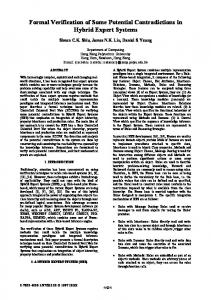
4.2.1 Validation of the component models The reachability graph for each component model was computed and compared with the automata table describing the original automaton. Two types of errors were detected: (1) Output signals which were set and not correctly reset. This leads to a di�erent number of states in the original automaton and in the reachability graph of the model. (2) The state transition relation was not correctly speci�ed in the table. In this case, the model may have places without pre- or post-transitions or unbounded places. These properties were checked via structural analysis. These errors are due to inconsistencies between the (manually drawn) graphs and the (manually typed) tables. Checking the above properties can give hints to such errors. 4.2.2 Veri�cation of interconnected systems 1. Analysis of liveness properties (in the sense of Petri nets) It could be shown that no deadlocks exist. Dead transitions were found by analysis. Such dead transitions represent pieces of code that will never be executed in the actual controller implementation. Such code � if it is the result of a design error � can be removed without changing the behavior. Figure 7 shows an example. All transitions with dotted arcs are dead. The reason is that transition t27 and t24 can �re only if place p133 is marked. This place, however, can be marked only after �ring transition tx . This transition, in turn, depends on the marking of place p19 . If this place is marked, t24 and t27 are not enabled since their pre-places are not marked. This design error was caused by concurrent and
independent design on the single interacting automata. The individual developers of the design were not able to overlook the global behavior. It was extremely useful for interpretation of these results and changing the design that each state transition in the design is uniquely represented by one transition in the model. Between one and �ve dead transitions were found after each redesign of a component. 2. Modelchecking using CTL formulae CTL formulae were derived from the original software or system requirements speci�cation [SRS98]. Approximately twenty requirements were checked. We cannot present all these. Approximately 80 % of these requirements, however, were checked using more or less the same scheme as described below [Pan98]. The �rst original requirement is that the supervision signal must always correctly indicate the state of the level-crossing [SRS98]. This assertion is a predicate containing two atoms. The �rst one is the marking of a place psup representing the activated supervision signal of the LC. The second one characterizes directly via the marking m(pof f ) = 1 the completely deactivated (unsecured) LC and via m(pon ) = 1 the completely activated (secured) LC. Hence, all reachable states must satisfy that m(psup ) = 1 is coincident with m(pof f ) = 0 or m(pon) = 1. The reachability graph is checked for a counterexample which violates this requirement. For better localization of a counterexample, this requirement was checked in two steps with two formulae.
Formula 1.)
LC; m0 j= EF (Pcrit1 ) with : Pcrit1 = [m(psup ) = 1] ^ [m(pof f ) = 1]
It was checked with this formula whether a state is reachable from the initial state m0 in which the supervision signal indicates the completely secured LC while the LC is completely unsecured (all barriers open, all lights o�). It was shown that this formula was true. Although the occurrence of such a behavior is very unlikely, it represents a severe risk. The design error was analyzed using trace analysis. After discussion with the system experts of the company, the design was corrected. After redesign the above formula was proven to be false.
It was shown that there is at least one reachable state where Pcrit2 is true. Trace analysis showed that an unpredictable failure of a light can be the reason for reaching such a state. This exception cannot be avoided by means of control. One has to prove, however, that such a state is always a transient one. This means that after a �nite number of state transitions a safe state is reached. This has to be proven. Another predicate Psaf e has to be de�ned for that purpose that characterizes the deactivation of the supervision signal and the permanent deactivation of the level-crossing: Hence, one gets a new formula:
Formula 2.1)
LC; m0 j= EF (Pcrit2 ^ :AX (Psaf e)) with : Psaf e = [m(psup ) = 0] ^ [m(pon) = 0]
This formula checks whether there is a path in the reachability graph where Pcrit2 becomes true and not all direct successor states ful�ll the safe predicate. Such a behavior exists. The analysis revealed that there are successor states of the �rst state which ful�lls Pcrit2 which also ful�ll Pcrit2 due to state transitions which do not change the value of that predicate. Hence, the formula to check had to be modi�ed as follows:
Formula 2.2)
LC; m0 j= EF (Pcrit2 ^ :AF (Psaf e ))
This formula is false. Hence, it could be shown that each critical state will lead to a safe state. The quantitative timing aspect which is of fundamental interest in this case could not be detected since our model is untimed. By means of a further version of SENA, one could at least determine the maximum number of state transitions between the �rst time that Pcrit2 becomes true and the �rst time that Psaf e becomes true. With a worst-case estimation of the time which is needed for each state transition, one could at least come up with a worst-case estimation of the error-revealing time [FN98].
4.3 Results
Functional requirements which were checked can be partitioned into three groups: � Proof of absence of dangerous behavior. � Proof that critical states are always followed by safe states. � Proof that certain events always lead to approIt was checked with a second formula whether thepriate actions while considering also all possible re is a state where the supervision signal indicates a exceptions. completely secured LC while the LC is not yet comAnother main result was that a considerable pletely secured. amount of speci�ed requirements were not ful�lled Formula 2.) by the design. This was due to a couple of exceptions which were not speci�ed. These exceptions could LC; m0 j= EF (Pcrit2 ) be revealed. It could be shown that under these exwith : ceptions, which can not be avoided, the controller Pcrit2 = [m(psup ) = 1] ^ [m(pon) = 0] design meets the requirements. 7
Using Temporal Logic Speci�cations. ACM Transactions Dead transitions were found. They are not releon Programming Languages and Systems 8: pp. 244-263, vant for safety properties. They were eliminated, ho1996. wever, since they would have been implemented by [DDK98] Damm W., Döhmen G., Klose J.: Secure Decencode which would have been never tested in the test tralised Control of Railway Crossings. Submitted for puphase of the design. This contradicts to the requireblication, 1999. ment that each line of code must be executable in [DFG98] DFG-Referenzfallstudie: Spezi�kation der Steuerung und Sicherung von Fahrzeug und Fahrthe test phase of the implementation.
5 Conclusion
weg für zusatndsvariable Fahrwegelemente beim funkbasierten Fahrbetrieb im spurgebundenen Verkehr. DFG-Schwerpunktprogramm �Integration von Techniken der Softwarespezi�kation für ingenieurwissenschaftliche Anwendungen� http://tfs.cs.tuberlin.de/projekte/indspec/SPP/index.html [EN128] CENELEC: prEN 50128 � Railway Applications: Software for Railway Control and Protection Systems. January 1997. [FN98] Fenner W., Naumann P.: Verkehrssicherungstechnik. Publicis MCD Verlag, Erlangen und München, 1998. [Hel96] Heljanko, K.: Implementing a CTL Model checker. In: Workshop Concurrency, Speci�cation & Programming . Humboldt�Universität zu Berlin, Institut für Informatik, Informatik�Bericht Nr. 69, pp. 75-84, Berlin, Germany, 1996. [HL98] Hanisch H.-M., Lüder A.: A Signal Extension for Petri Nets and ist Use in Controller Design. submitted to Fundamenta Informaticae 34, 1998. [HNSY94] Henziger, A., Nicollin, X., Sifakis, J., Yovine, S.,: Symbolic model checking for real-time systems. Information and Computation 111:193-244, 1994. [LRRA98] Liggesmeyer, P., Rothfelder, M., Rettelbach, M., Ackermann, T.: Qualitätssicherung Softwarebasierter technischer Systeme- Problembereiche und Lösungsansätze. Informatik-Spektrum 21. Springer-Verlag 1998, pp. 249-258. [Pan98] Pannier T.: Spezi�kation, Veri�kation und Implementation einer mikrorechnergestützten Bahnübergangssteuerung. Diplomarbeit, Otto von Guericke Universität Magdeburg, Fakultät Elektrotechnik, Institut für Automatisierungstechnik, 1998. [SH97] Starke P.-H., Hanisch H.-M.: Analysis of Signal/Event-Nets . 6th IEEE International Conference on Emerging Technologies and Factory Automation ETFA-97, Los Angeles, USA, September 1997. [SK91] Sreenivas R. S., Krogh B. H.: On Condition/Event Systems with Discrete State Realizations Discrete Event Dynamic Systems: Theory and Application 1. pp. 209236, 1991. [SRS98] Siemens AG VT: System�Requirement Speci�cation SIMIS LC. Siemens VT 1 P GFB, 1998. [Rei98] Reif, W.: Software-Sicherheit mit formalen Methoden. Softwaretechnik'98. Paderborn. pp. 3-9.
Obviously, a complete proof of the correctness of the controller could not be performed due to the current limitations of the method. We think, however, that the work has at least led to an improved controller design. The company sta� is convinced that these improvements would have been impossible without formal methods. Bringing formal methods like model checking to practical applications is, however, rather an evolutionary process than a �breakthrough�. Both parties � practitioners as well as academic researchers � have to move. To our experience, there is a strong need for practitioners to �nd means for improving their design methodology. The best framework and tool developed in academia, however, will not be accepted if it ignores the basics for coming up with formal models which are laid in practice. Controller design in practice is performed in a modular and incremental way. Hence, formal methods should provide means to follow such a way as well. Furthermore, to our experience, the simpler the formal model is the more it is accepted. We think that a way of block�diagram modeling technique is probably a good and well�accepted way to establish models. It is obvious that this work is only a very small step towards a methodology and a collection of tools that cover the entire design process from the speci�cation to the actual hardware and software. Providing this is far beyond the capabilities of one or two single groups of researchers. The most signi�cant result we gained is that it is really possible and desirable to bridge the gap between the theoretical work on model checking and veri�cation that took shape during the last few years and the arising needs Manuskripteingang: 29. Januar 1999 of practice to apply formal methods.
6 Acknowledgement The work was partially supported by the Deutsche Forschungsgemeinschaft under Reference Sta 450/41. References
[AH96] Alur R., Henzinger T. A., Ho P.-H.: Automatic symbolic veri�cation of embedded systems. IEEE Trans. on Software Engineering 22(3), pp. 181-201, 1996. [CES86] Clarke, E. M., Emerson, E. A., Sistla, A. P.: Automatic Veri�cation of Finite-State Concurrent Systems
8