One BRAM can implement FIFO with size 512 words by 32 bits. If larger FIFOs .... [4] Claudiu Zissulescu, Todor Stefanov, Bart Kienhuis,. Ed Deprettere. LAURA: ...
Modeling and FPGA Implementation of Applications using Parameterized Process Networks with Non-Static Parameters Hristo Nikolov Todor Stefanov Ed Deprettere Leiden Institute of Advanced Computer Science (LIACS), Leiden University, The Netherlands {nikolov, stefanov, edd}@liacs.nl Abstract Today’s applications in the domains of multimedia, signal processing, etc. consist of a number of interacting components. If the way of interaction is determined at run time, we say that an application is non-static. In general, complex real-world applications are non-static. In this paper, we summarize a method for modeling and FPGA implementation of applications that have a specific type of non-static behavior. This method is based on program decomposition resulting in the generation of truly Parameterized Kahn Process Networks and their mapping onto FPGAs. We automated the method by integrating it in our tools Compaan/Laura. The efficiency of our method is demonstrated by an implementation of a real-world application taken from the automotive domain.
1. Introduction Today’s embedded applications in the domains of multimedia, imaging, or signal processing consist of a number of components interacting between each other. In general, the way of interaction is data dependent and determined at runtime. We call such applications nonstatic. A real-world industrially relevant example is the Low Speed Obstacle Detection (LSOD) application used in the European IST research project ‘Camellia’: core for ambient and mobile intelligent imaging applications [21]. Its objective is to build a smart imaging hardware core. The core is low-cost, low-power, and flexible enough to be used in a large class of embedded mobile smart imaging consumer applications. The need of high performance requires this kind of applications to be implemented as parallel systems. To do this, we believe that such applications are most conveniently specified using the Kahn Process Network (KPN) Model of Computation (MoC) [7]. This is because distributed control and distributed memory are two main features of a KPN that allow to program heterogeneous multiprocessor systems relatively easy and to generate highly efficient hardware implementations [5] [7] [11] [12] [16]. However, deriving KPN specifications for an application is difficult and time consuming process. Designers have to study the application in order to identify
possible task-level parallelism that is available and to reveal it. Therefore, in our research group we develop the Compaan/Laura design flow [1] [4] [15] [16] which aims at helping the designers to derive KPN specifications from an application described as a sequential program and to implement these KPNs in software and/or hardware. The first tool, Compaan, takes an application described as a sequential program in Matlab and automatically generates functionally equivalent KPNs. Laura operates as a backend tool for FPGA mapping of a KPN specification generated by Compaan. Until recently, the sequential program had to be a parameterized static affine nested loop program. For such a program the behavior can be completely analyzed at compile time. Although, this is a nice property, many applications can not be specified as static programs. With the description of the LSOD application in the following subsection we show an example of a program that has the specific non-static behavior we consider in this paper and we outline the problems in our design flow introduced by this behavior.
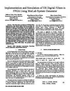
1.1 Motivating example – LSOD application The LSOD application is intended to detect and to track objects in front of a car in traffic. The output of the system presents accurate spatial positions for targets – cars, pedestrians, etc. The structure of the LSOD application is depicted in Figure 1. Five general image processing components help to find new targets, and to track existing targets. The components implement vertical edge detection, motion segmentation, shadow detection, symmetry detection, and lights detection. The result from each component is collected by a particle filter component [14]. The output is the result of evaluated likelihood functions. The first step is to obtain two images from a given camera picture. They are named high and low resolution images and are depicted by the two dark rectangles in Figure 2. Applying the different algorithms on these images, hypotheses whether cars exist are computed. Possible targets are defined as coordinates and dimensions of rectangles belonging either to the high or low resolution image. Two possible targets are presented by the white rectangles, surrounding the cars in Figure 2. Vertical summing is applied on the target area, based on edge
detection operator, and then used to support or decline the existence of the targets. The edge detection part of the LSOD application in Figure 1 is an example of a non-static program. It is shown in Figure 3 and we consider this example for further analysis. This program is non-static because the function getLSODTarget in line 2 initializes variables Height and Width used as loop bounds. The variables define the size of a target and the amount of data to be processed. Since, a target is moving in front of a camera, the positions and dimensions will differ for different targets in the frame and for one and the same target in different frames. That is why the values of variables Height and Width are not known at compile time which makes the LSOD application to have a non-static behavior. As a consequence the Compaan/Laura design flow can not handle the program shown in Figure 3. The solution of this problem is the contribution of the paper. Our approach extends the range of the applications Compaan/Laura design flow can handle. The solution is based on program decomposition that results in generation of parameterized KPNs suitable for software and hardware implementation. Applying this technique we can model and implement efficiently applications that have non-static behavior using the KPN MoC.
Edge Detection
Motion Image ... Segmentation Processing n
Particle Filter Particle updating using likelihood functions Output
Feedback to image processing modules
Figure 1: Low Speed Obstacle Detection application framework. Results from different image processing components are collected by a particle filter.
1.2 Related work In [2] Bhattacharya et al. describe a parameterized dataflow framework. They extend the Synchronous Dataflow (SDF) MoC to Parameterized SDF (PSDF) targeting software implementation of parameterized systems for DSP. They use a hierarchy discipline that allows subsystem behavior to be controlled by sets of parameters, which can be configured dynamically. Dealing with parameters greatly enhances the utility of the model. The relation to our work is that we also use a parameterized MoC, in our case KPN, for modeling and implementation. However, modeling applications using
PSDFs is done manually and needs some consistency analysis at run time, whereas our KPN specifications are derived automatically and are correct by construction so that no consistency checks are needed. In [9] van Dijk et al. propose an extension of the KPN MoC. They introduced a simple non-deterministic construct and called the resulting network Context-Aware Process Network (CAPN). They show that these networks are capable of handling external events. The relation to our work is in the sense that with our parameterized KPN we also can handle external events if the parameters are changed from an external environment dynamically, at runtime. The difference is that in our KPN we do not introduce non-deterministic behavior.
Target 1 Target 2
Figure 2: LSOD applied on real data. The vehicles in front of the camera are detected and tracked. The dark rectangles depict the area of the image that is processed.
Celoxica [20] provides electronic design automation (EDA) products for system design and implementation. Their products implement software-compiled system design, allowing hardware implementation from a high level, C-based language called Handel-C. The relation to our work is that our Compaan/Laura tool chain also can generate hardware starting from a high level language Matlab. The difference is that in our case the underlying MoC is KPN, whereas Celoxica uses Communicating Sequential Processes (CSP). The KPN is suitable for stream-oriented applications while the CSP MoC is more suitable for control-oriented applications. Another difference is that the Celoxica design flow puts fewer restrictions on the input program. However, the designer has to reveal the inherent parallelism in the program and to describe it manually. In our case this is done automatically by Compaan/Laura which reduces significantly the design time. In [13] MATCH (MATlab Compiler for distributed Heterogeneous computing systems) compiler project is presented. It is further commercialized by AccelChip Inc [18]. The objective of the MATCH compiler is to allow developing an efficient code for distributed heterogeneous
computing systems. The compiler takes MATLAB descriptions of an application, and automatically maps it onto Field-Programmable Gate Arrays (FPGAs), embedded processors and digital signal processors. It uses both IP cores and automated generation of C code for the DSP and RTL VHDL code for the FPGAs. The relation with Compaan/Laura design flow is that it also generates C (or Java) code from a Matlab specification that can be compiled either for DSP, RISC or general purpose processors, and VHDL code for hardware mapping using IP cores. However, our approach has major differences described bellow. 1
for j=0:1:Targets,
2
[Height ,Width] = getLSODTarget();
3 4 5 6 7
for j=0:1:Height+1, for i=0:1:Width+1, [img_in(j,i)] = ReadTarget() ; end end
8 9 10 11 12 13 14 15
for j=1:1:Height, for i=1:1:Width, [img_out(j-1,i-1)] = SOBEL(img_in(j-1 , i-1), img_in(j-1 , i+1), img_in( j , i-1), img_in( j , i+1), img_in(j+1, i-1), img_in(j+1, i+1) ); [img_out(j-1,i-1)] = ABS_F( img_out(j-1, i-1)); end end
16 17 18
for i=0:1: Width-1, [vsums(i)] = ZERO(); end
19 20 21 22 23
for j=0:1: Height-1, for i=0:1: Width-1, [out_vsums(i)] = VSUM(vsums(i), img_out(j,i)); end end
24 25 26
for i=0:1: Width-1, [out(i)] = WriteVSUMResult(out_vsums(i)); end
27 end
Figure 3: Matlab source code of the edge detection part of the motivating example. The size of a target is specified by variables Height and Width set by getLSODTarget function and used as loop bounds.
A MATCH compiler implementation has a centralized control. The compiler generates a main control thread that makes remote procedure calls of functions running on different processors. In our work we have distributed control due to the KPN MoC we use. It allows naturally exploiting the parallelism hidden in the application. The MATCH compiler performs automated mapping and scheduling of resources using a mixed integer linear programming. The Compaan/Laura design flow also uses integer linear programming to generate KPN specification. It can be mapped easily in software or hardware. The implementation can be clustered and mapped on different resources (mixed hardware/software implementation) but still the clustering has to be done manually. For the software part of an implementation the MATCH compiler uses the Single Program Multiple Data
(SPMD) model, where all processors execute the same program but on different portions of data. The loop bounds in the loop nest are partitioned so that each processor executes only those iterations for which the data resides on. In our approach we use KPN MoC and there is no need to partition the loop bounds to achieve an efficient implementation. The Match compiler can handle loop bound expressions that may have compile-time unknowns. In the paper we also show how we deal with some compile-time unknowns and how we are able to generate parameterized implementations and to change the parameters at runtime. In the FPGA mapping of an application obtained by MATCH compiler, each user function is converted into a process in VHDL. The functions share a common memory. This is a major difference from our work. For each function our design flow generates a process of a KPN specification. The structure of a process is described in Section 4.2. A process assumes that input data is read from FIFOs and the result is written to FIFOs that are distributed between the processes.
1.3 Paper outline First, a limited background about KPNs and Compaan generated KPNs (CPN) is given. Then in Section 3 we present our solution approach for dealing with non-static programs. Section 4 presents the implementation of the edge detection part of the LSOD using Compaan/Laura design flow. With an FPGA mapping we describe the consequence of the solution approach to the implementation of parameterized KPNs in hardware. Results are presented and commented in Section 5. Finally, we conclude the paper.
2. Background A KPN [7] assumes a network of concurrent autonomous processes that communicate in a point-topoint fashion over unbounded FIFO channels, using a blocking read synchronization primitive, i.e., a process that attempts to read from an empty channel is stalled until the channel has sufficient data to complete a read action. Each process in the network performs a sequential computation concurrently with the other processes. A well-known characteristic of KPNs is that their MoC is deterministic. Always for a given input data, one and the same output data is produced. This input/output relation does not depend on the order in which the processes are executed. As the control is incorporated into the processes no global scheduler is present. Moreover, the concurrency between the processes is naturally exploited, since each of them can be executed if there is data on their input ports. Compaan generated KPNs (CPN) are seen to be a subset of KPNs. This is because of the restrictions put on the sequential program. As we mentioned, Compaan
converts parameterized nested loop programs to inputoutput equivalent parameterized KPN specifications. Compaan generates a process for each function in the program (i.e. the bubble PS_5 in Figure 4 corresponds to the function VSUM, line 21 in Figure 3), and edges between processes (the arrows in the Figure 4) in accordance with the data dependences in a program.
2.1 Iteration space of process in a Compaan generated KPN A process is generated for each function present in a program. A process firing represents one execution of the function call. The iteration space of a process is defined by the bounds of nested loops, surrounding the function and represents the number of the firings of the process. Each process has its own iteration space, its own notion of time.
2.2 Run of a Compaan generated KPN When a process finishes the execution of the last iteration from its iteration space, one run of the process is completed and the process is suspended. Since there is no global scheduler, the processes can run concurrently if there is data on their input ports. The amount of parallel process executions depends on the program a CPN represents. When each process of a CPN completes its run, one run of the process network is defined. The KPN MoC is suitable for processing endless, streaming data. It is easy to describe an application in software that never ends, but this complicates the dependence analysis a lot. Therefore, it is reasonable to describe the application in terms of processing a finite piece of data, i.e. a frame or number of frames (if images are processed). In general, when a CPN finishes the processing of the current data (finishes its current run) it stops. However, if there is new data to be processed, the network is run again. This can be done automatically, i.e. when a process completes its run it starts another run if there is new data. As a result we have overlapping process executions between different runs of a CPN, leading to maximum performance. In our implementations we have also the ability to stop and to start a CPN between different runs. In that case we loose the overlapping of process executions in different runs but we gain an easy way to control the CPN when it is a part of a complex system. This ability to control a CPN does not deal with scheduling of a CPN. In this manner, streaming data can be processed by CPNs, generated after a simplified dependence analysis of the initial program and with reduced control logic. We exploit the capability to start and stop CPNs in our solution approach described in the next Section.
3. Solution approach The non-static program in Figure 3 can be divided in two parts that are static programs. The first part, function getLSODTarget in code line 2, defines the size of the current target by variables Height and Width. The second part, code lines 3-26, applies the vertical edge detection algorithm on the current target. This code can be seen as a parameterized static affine program if the variables Height and Width are interpreted as parameters. Since, the two parts are static programs each of them can be processed by the Compaan tool, thereby generating two KPNs as shown in Figure 4. Given that KPN1 corresponds only to one function, getLSODTarget, we ran the function as a software program without processing it through Compaan. KPN2 is a process network generated by Compaan as a result of the initial program represented by code lines 3-26 in Figure 3. Each process (bubble) in Figure 4 represents a function in the initial program (code lines 5, 10, 13, 17, 21, and 25). The processes communicate between each other through data channels, depicted as solid black arrows (edges) in Figure 4. The KPN2 is parameterized by Height and Width, which values are set at runtime by getLSODTarget function. The interaction between ‘KPN1’ and KPN2 is realized through control channels, shown as dashed arrows in Figure 4. The values of the parameters are communicated via these channels. The problem is that we have to add control to the KPN2 to enable the update of certain parameters from outside the network. The questions that arise are: when to update the parameters, and how to update them in order to preserve the consistency of the process network? A Kahn process network is a parallel model of computation and due to the distributed control there is no global schedule present. That allows to incorporate easily the control for updating the parameters into the processes. ED_1 ED_2 ED_3
ED_8
ED_7 PS_1
ED_4
PS_3
PS_4
ED_10
ED_5 ED_6
PS_5
ED_11
PS_6
ED_9 PS_2
KPN2 ‘KPN1’ getLSODTarget
Dataflow Control flow
Figure 4: The KPN generated by Compaan from the vertical edge detection part of the motivating example. The getLSODTarget function is not processed by the Compaan tool.
In our Compaan/Laura design flow the parameters have to be fixed before each implementation. Each set of parameter values defines one instance of a CPN. The analysis performed by the tools guarantees that each
instance is consistent for the values of the parameters within a specified range. Using this feature and due to the way of interaction between the dataflow and the control flow we are able to deal with the parameters without disturbing the consistency. We introduce three conditions and following these conditions we can model control in parameterized KPNs with non-static parameters. The aim of the conditions is to preserve the deterministic behavior and to deal with parameters at runtime: C1: Each interaction of a CPN with its environment includes one run of the process network. C2: Updating parameters is done before a new run of a CPN. C3: Each set of parameters initiates a new run of a CPN. Following the conditions guarantees that if the network is deadlock-free before introducing the parameters it will not deadlock after the parameterization. This is because it is not possible to send new parameters to the process network while it is still running and then the completion of the current run to be made according to their new values. We propose and implement a simple mechanism to send and update the values of the parameters that is compliant with the defined conditions above. The parameters are updated before each run of the process network. That allows sending parameters to the CPN at any time, however they will be updated after the current run is completed and just before the new run is initiated.
Dependency Graph (DG) of the initial program is created. Then the DG is converted to a Polyhedral Reduced Dependence Graph (PRDG) data structure, which is a compact mathematical representation of the DG in terms of polyhedrons. Finally, a process network is generated from the PRDG. The parallel processes communicate with each other in accordance with the data dependency given in the DG. The vertical edge detection program (Figure 3, without code lines 1 and 2) is described as nested loops program with parameterized iteration space and several functions. The possible dimensions of a target are described by the parameters Height and Width, specified in a range. Then, a KPN specification is generated by the Compaan tool: a process for each function in the program; and edges between processes, according to the data dependences (KPN2 in Figure 4). By specification the CPN is consistent for each value of the parameters within the range, guaranteed by dependence analysis.
4.2 Laura tool Laura accepts as input CPN specification, and generates synthesizable RTL hardware specification in several steps [4]. It targets FPGAs as an implementation technology. First, the CPN is converted to an internal hardware model. A node is generated for each process from the process network. The edges between processes are substituted with hardware FIFO channels that are intermediate storage elements in the communication between nodes as shown in Figure 5. To generate the HDL code Laura uses additional information about the token size, IP Cores, target architecture and the parameters.
4. Implementation ...
In this section we show the implementation of the motivating example by integrating the solution approach in the Compaan/Laura design flow. The first part of the decoupled program (getLSODTarget function) was implemented in software. The vertical edge detection algorithm of the example (the second part) was implemented in hardware using our design flow and described in the remaining part of the paper. It corresponds to KPN2 in Figure 4.
4.1 Compaan tool Compaan tool is a compiler [1] that fully automates the transformation of applications described in Matlab into KPN specification. It can be in the forms of Y-chart Application Programmers Interface (YAPI) [6] (C++ code for system level application modeling and performance analysis), or Ptolemy [8] (Java code that can be used for functional simulation in Ptolemy II). A robust dependence analysis is performed [10] [17] that reveals the parallelism hidden in the sequential source code. As a result a
INIT
...
SOBEL
ABS
VSUM
OUT
ZERO
Control Bus
Figure 5: Laura generated hardware model of the KPN2 in Figure 4. The functionality is realized by processes communicating between each other through FIFOs. The purpose of the Control Bus is to transfer the parameters to each node.
A token is a piece of data that is communicated between nodes through the channels, in our case one pixel value. In the design flow each function is implemented by an IP core written in VHDL. The needed information about each IP is taken from a library. Target architecture gives information about the FPGA family that will be used for the implementation and the interface logic for the FPGA environment – host PC for example. To be able to generate and to manage the hardware implementation of
parameterized KPN, information about the parameters is used. A common control bus is connected to each node – the dashed arrows in Figure 5. It is used to set the parameters from outside the CPN. Introducing the concept of parameters into the hardware model of the process network does not break the consistency of the network if the defined conditions in Section 3 are respected. To describe how the parameters are updated, first we explain the structure of a node, shown in Figure 6. The node consists of three parts: communication, computation, and control part. The communication part contains Read and Write Units. A set of input data ports belongs to the read unit and a set of output data ports belongs to the write unit. The number of the input/output ports is equal to the number of the edges going in (respectively out of) the process as they are depicted in the CPN structure (solid arrows of KPN2 in Figure 4). The read unit is responsible for getting data from proper channels (FIFOs) at each iteration. The write unit is responsible for writing the result to proper channels (FIFOs) at each iteration. Selecting a ‘proper channel’ at each iteration means to follow a local schedule incorporated into the read and write units. These local schedules are extracted from the CPN specification automatically by Laura tool. Also, the read unit implements the blocking read mechanism described in Section 2. Similarly, the write unit implements a blocking write mechanism. Laura tool estimates the sizes of the FIFO channels and since, they are finite values it could happen that the channel is full when a node attempts to write data in it. If such situation appears, the node is suspended until the channel is ready to accept the data. Node Empty Read 3-stage control pipeline
CTRL UNIT
Write Full 3-stage control pipeline
DATA
DATA READ UNIT
EXEC UNIT
FIFOs
WRITE UNIT
FIFOs CONTROL BUS
Figure 6: The structure of a node of a CPN
The computational part is represented by the execution unit. It gets data from its inputs and produces data on its outputs. The execution unit is realized as a wrapper of an IP core. The core can be pipelined or not. The number and the size of the input/output ports of the core, the number of the stages of the pipeline (or respectively the number of the clock cycles needed to produce data) is taken from a library. To be incorporated into a node, an IP core has to have ‘Enable’ and ‘Ready’
signals. ‘Enable’ signal allows running the core when there is data to be processed and suspended otherwise. The ‘Ready’ signal indicates whether the data on the IP outputs is valid or not. In the implementation of KPN2 we use IP cores for sobel, absolute value, zero, and vertical sum functions. The function of the control unit is to synchronize the operation of the other units and to make them to work together. Node
SHIFT REG.
CTRL FIFOs
REG. FILE P1 P2
...
CTRL FIFOs
CTRL UNIT PCTRL LOGIC
Pn
DATA PATH
PCTRL
Din READ UNIT
EXEC UNIT
Dout
DATA PATH
WRITE UNIT
CONTROL BUS
Figure 7: Loading and updating parameters. Read Unit is depicted as an example of the logic involved in updating the parameters
There is no additional latency in the data path added to the CPN by the node. The execution unit (the IP core) reads the input data directly from the FIFO outputs and store the results directly in the FIFOs. If the IP core contains only combinational logic, the combinational data path (from an input FIFO to an output FIFO) becomes the critical path in the design that sacrifices the performance. To avoid that, we put registers at the outputs of the IP core. In that case one clock period delay is added to the data path. In each Read and Write unit the control logic (the local schedule) is implemented as a pipeline that has three stages. It could be seen that each node adds to the CPN 6 clock periods additional delay and in case of a network with many nodes the delay would become significant. However, as we stated earlier, each process (node) has its own notion of time. Moreover, read and write pipelines work independently. For that reason filling the control pipelines begins in parallel immediately after the CPN starts a new run. As a consequence, latency of only 3 clock periods is added to the whole CPN regardless of how many nodes it contains and how they are connected between each other.
4.3 Updating the parameters Updating the parameters is based on a double buffering technique. To implement this technique
hardware buffers are placed in each unit of a node. In Figure 7 a read unit is taken as an example. The first buffer is a shift register and the second is a register file. The parameters are sent one after another and they are stored temporary in the shift register in each unit. Depending on CPN specifications generated by Compaan it can happen that not all the parameters are used in each unit. However, all the parameters are stored in the shift registers in order to simplify the process of sending parameters to the nodes of a CPN. The real update of the parameters is done by transferring them in parallel from the shift registers to the register files. Sending parameters to the shift registers can be done at any time. However the transfer to the register files must be done after the completion of each run of a CPN in order to keep its deterministic behavior as explained in Section 3.
5. Experiments and results In this section we describe the experiments and the results we have obtained by mapping the edge detection part from the LSOD application on FPGA platform. We did these experiments with Compaan/Laura in order to validate the solution approach presented in this paper and to evaluate the performance of the generated hardware in terms of speed and resource utilization. In the experiments we used ADM XRC-II, FPGA prototyping board manufactured by Alpha Data Parallel system Ltd. [19] The ADM XRC-II is a high performance PCI card equipped with Xilinx FPGA. The board is connected to a Pentium based personal computer (PC) running at 1.8 GHz. The FPGA board consists of Virtex-II (XC2V6000-FF1152) device and 6 banks of static memory, 256K x 32bits each. The memory can be accessed either from the PC or the FPGA. Transferring data between the board and the main processor is managed by a PCI controller.
5.1 Synthesis results For the synthesis and hardware implementation we used the ISE XILINX Foundation design environment software. The results are presented in Table 1. Resource utilizations are given for the IP cores, the logic involved in the CPN implementation and the interface logic used for the PCI and memory communication. The FPGA resources are grouped into slices that contain combinational logic (4-Iinput Look-Up tables), distributed memory (Flip-Flops); and dual port memory blocks (BRAMs). Laura tool automatically instantiates BRAMs for implementation of the FIFO channels in a process network. One BRAM can implement FIFO with size 512 words by 32 bits. If larger FIFOs are needed, Laura tool generates them by usage of optimal combinations of BRAMs.
In the current implementation we use IP cores for sobel, absolute value, zero, and vertical sum functions. They consist of basic synthesizable operations. Sobel contains two additions, one subtraction and shift operations. Absolute value is implemented with one comparison, one addition and one negation. Zero is constant zero. Vertical sum contains only one addition. It is obvious that the resource utilization of such simple functions will be low – in our case only 424 slices. From the table it is seen that the logic needed for the implementation of the CPN structure and control is almost twice larger than the processing units (IP cores). However, the area of the controllers does not directly depend on the size of the data and the size of the IP cores they control larger IP cores will not lead to increased control logic. For example, in our previous work we implemented part of a Motion JPEG using Compaan/Laura design flow, where the IP cores (Discrete Cosine Transform and pre-shift operation) utilizes 4 times more FPGA resources than the CPN control logic. The parameterization of a hardware implementation of a CPN increases only the number of the Flip-Flops used in realizing the shift registers and the parameter registers. That increase depends on the number of the parameters defined in the initial program.
5.2 Performance results The LSOD application runs as a software program on the host PC. As input data the program takes high resolution image, low resolution image, positions and dimensions of two targets for which we have a reference data. It calculates each target to which image belongs, extracts the data from the proper image and stores it into the memory of the FPGA prototyping board. The described steps above model the behavior of function getLSODTarget in Figure 3. For one run of the CPN, one target is processed. Thus, for each target present in the image the process network has to be run again. To model this behavior the LSOD application does the following steps: 1. 2. 3. 4. 5.
Store the pixel data of a target into the FPGA board memory; Set (send to the FPGA) new parameters; Run the CPN; Read back the result (from the FPGA board memory) when the processing is finished; Repeat the steps above for each target.
The part of the LSOD application running on the PC and the CPN communicate pictures (loading the data to the FPGA board memory and read back the results), but the CPN processes pixels. To estimate an interpretable performance rate (i.e. number of targets per frame or per second) first, we
assumed that there are infinite numbers of targets in the input image. Then we set the dimensions to be equal to the first target that we have reference data for. We ran the application following the five steps above for one second and counted how many times the CPN was run. This is the number of targets per second. For an input data rate of 25 frames per second we divide the results by 25 thus obtaining number of targets per frame at 25 frames per second. Then we set the target dimensions to be equal to the second target that we have reference data for and ran the process network again for one second. Finally, we made the targets to have the largest possible size: equal to the high resolution image, and ran the application again for one second. With the last dimension the system can process 9 targets per frame at 25 frames per second. But the target is large as the whole image and in case of nonoverlapping targets it is not possible to have more than one target per frame. The results are presented in Table 2. The main processor works at 1.8 GHz and the board works at its maximum: 66 MHz. Table 1: Device Utilization (XC2V6000)
Utilization IP Cores CPN Control Interface Logic Overall
424
4-Input LUT 574
Sliced FFs 388
816
1056
621
11
470
665
717
-
1710 (5%)
2295 (3%)
1717 (2%)
11 (7%)
Slices
BRAMs -
The parameterization of the system does not sacrifice the measured performance. We computed that the CPN needs N(2M+1)+12 clock cycles to process one target with size NxM pixels. This means that the maximum achievable performance is 1658 targets per second (180x110 at 66MHz). The difference with the measured performance is about a factor of 7. We found out this is due to the card drivers (i.e. the time needed for setting a DMA channel) and the function calls under Windows OS. We are limited in terms of performance by the PCI interface connecting the prototyping board and the host processor. However, even with this restriction we achieve performance which satisfies the real-time requirements of this application. Table 2: Measured performance. T/F@25F/sec means “targets per frame at 25 frames per second”
Target size
58x60
40x45
180x110
Targets/sec
1089
1843
229
43
74
9
T/F@25F/sec
To ensure that our hardware implementation works correctly we compared the results from the FPGA mapping with a reference data that we have. We did not perform an RTL (cycle accurate) simulation of the generated hardware because the generated CPN is correct by construction. There is no need to test the IP cores as well. That reflects on a significantly reduced development time.
6. Conclusion We proposed a method for modeling and FPGA implementation of non-static programs using parameterized KPNs. We applied our method on an image processing application, namely Low Speed Obstacle Detection and generated a parameterized hardware implementation using our Compaan/Laura design flow. From the experiments and results we conclude the following: • The parameterized KPN model we presented allows us to implement easily parameterized systems due to the fact that the CPN has a self-timed schedule. The parameters are updated at runtime without introducing non-deterministic behavior of the system. • The implementation results in a high performance parameterized system capable of processing data at more than 25 frames per second. This rate is the real-time requirement in many image processing applications. • The KPN MoC used in our automated Compaan/Laura design flow results in effortless analysis, debugging, and tuning of the system. • Starting from an application specified as a sequential program it is a matter of hours to go to a hardware implementation as CPN. This is because its functionality is realized by integrating IP cores in a communication network where the control and the communication hardware are generated automatically by our tools.
7. Acknowledgment The research is supported by the PROGRESS program of the Dutch Technology Foundation STW. The authors would like to acknowledge W. Kruijtzer from Philips Research; I. Cimpian, and B. Kienhuis for the discussions about the ‘Camellia’ project. Also, we would like to thank the anonymous reviewers for their constructive comments and helpful suggestions.
8. References [1] A. Turjan, B. Kienhuis, E. Deprettere. Translating
affine nested loop programs to Process Networks. Int. Conf. on Compilers, Architectures and Synthesis for Embedded Systems (CASES’04), Washington, Sep. 22-25 2004 [2] B. Bhattacharya, S. Bhattacharyya. Parameterized Dataflow Modeling for DSP Systems. IEEE Trans. on Signal Processing, 49(10), Oct. 10 2001. [3] B. Dwivedi, A. Kumar, M. Balakrishnan. Automatic
[4]
[5]
[6]
[7]
[8]
[9]
Synthesis of System on Chip Multiprocessor Architectures for Process Networks. In Proc Int. Conf. on Hardware/Software Codesign and System Synthesis (CODES+ISSS 2004), Stockholm, Sweden, September 2004. Claudiu Zissulescu, Todor Stefanov, Bart Kienhuis, Ed Deprettere. LAURA: Leiden Architecture Research and Exploration Tool. In Proc. 13th Int. Conference on Field Programmable Logic and Applications (FPL’03). E. de Kock. Multiprocessor Mapping of Process Networks: A JPEG Decoding Case Study. In Proc. 15th Int. Symposium on System Synthesis (ISSS’2002), pages 68-73, Kyoto, Japan, Oct. 2002. E.A. de Kock, G. Essink, W.J.M. Smits, P. van der Wolf, J.Y. Brunel, W.M. Kruijtzer, P. Liverse, and K.A. Vissers. YAPI: Application Modeling for Signal Processing Systems. In Proc. 37th Design Automation Conference (DAC’2000), pages 402-405, Los Angeles, CA, June 5-9 2000 Edwart A. Lee and Tomas M. Parks. Dataflow Process Networks. In Proc. of the IEEE, 83(5):773799, May 1995. Edwart A. Lee et al. Ptolemy II: Heterogeneous Concurrent Modeling and Design in Java. Technical report, University of California at Berkeley, 1999. UCB/ERL M99/40. H.W. van Dijk, H.J. Sips, E.D. Deprettere. ContextAware Process Networks. In Proc. of the 14th IEEE Int. Conf. on Application-specific Systems,
Architectures and Processors (ASAP’03), The Hague, The Netherlands, June 24-26, 2003. [10] P. Feautrier. Parametric integer programming. Operations research, 22(3): 243-268, 1988. [11] P. Lieverse, T. Stefanov, P van der Wolf, Ed Deprettere. System Level Design with SPADE: an MJPEG Case Study. In Proc. Int. Conference on Computer Aided Design (ICCAD’01), pages 31-38, San Jose CA, USA, Nov. 4-8 2001. [12] P. van der Wolf, Paul Lieverse, Mudit Goel, David La Hei, Kees Vissers. An Mpeg-2 Decoder Case Study as a Driver for a System Level Design Methodology. In Proc. 7th Int. Workshop on Hardware/Software Codesign (CODES’99), Rome, Italy, May 3-5 1999. [13] P.Banerjee, A.Choudhary, S. Hauck, N. Shenoy. The MATCH Project: MATLAB Compilation Environment for Adaptive Computing Systems. www.ece.nwu.edu/cpdc/Match/Match.html [14] Sanjeev Arulampalam, Simon Maskell, A Tutorial of Particle Filter for On-line Non-linear/Non-Gaussian Bayesian Tracking. IEEE Transactions on Signal Processing, pages 174-188, Feb. 2002. [15] T. Stefanov, B. Kienhuis, E. Deprettere. Algorithmic Transformation Techniques for Efficient Exploration of Alternative Application Instances. In Proc. “10th Int. Symposium on Hardware/Software Codesign (CODES’02)”, pages 7-12, Estes Park, Colorado, USA, May 6-10, 2002. [16] Todor Stefanov, Claudiu Zissulescu, Alexandru Turjan, Bart Kienhuis, Ed Deprettere. System Design Using Kahn Process Networks: Compaan/Laura Approach. In Proc 7th Int. Conf. Design, Automation and Test in Europe (DATE’04), Paris, France, Feb 16-20 2004. [17] W. Pugh. The Omega Test: A Fast and practical Integer Programming Algorithm for Dependence Analysis. Communications of the ACM 35, 1992, pages102-114 [18] www.accelchip.com/, AccelChip Inc. homepage [19] www.alpha-data.com/adm-xrc-ii.html, ADM-XRC-II. [20] www.celoxica.com, Handle-C. [21] www.iuma.ulpgc.es/camellia/, ‘Camellia’ home page