Modeling and Performance of Novel Scheme Dual Winding Cage Rotor Variable Speed Induction Generator with dc Link Power Delivery Lucian Nicolae Tutelea, Ion Boldea, Nicolae Muntean
Sorin Ioan Deaconu
Electrical Engineering Department Politehnica University of Timisoara Timisoara, Romania
[email protected]
Electrical Engineering and Industrial Informatics Department Politehnica University of Timisoara Hunedoara, Romania
[email protected] full power converter [5] that allow also energy storage in the dc battery are operate at fixed frequency that means almost constant shaft speed. A full power converter with bidirectional power flow [6] allows wide speed variation but the power converter cost is still to large for many applications. The wound induction machine allow to control the output power using low cost converter by controlling only the power transferred trough the rotor [7] or by using a two half controlled converter [8]. A configuration with two wound rotor induction machines could be used to avoid the slip ring and brushes [9], but especially in low speed applications the weight and cost of two machines is too large.
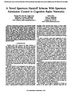
Abstract—In an effort to reduce the initial cost of a cage-rotor (robust) variable speed induction generator with full (100%) power PWM inverter, for a dc link local power bus, a novel dual stator winding configuration with a 50% rating PWM inverter and a capacitor and 50% diode rectifier (for additional active power delivery at high speeds capable of softstarting and low speed operation) is proposal in this paper. Machine circuit modeling with performance assessment for steady state and a circuit model for system feed forward controlled dynamics are proposed and backed up by numerical power and efficiency versus speed results. Preliminary experiments on a purposely built prototype already validate the essentials.
I.
INTRODUCTION
The double stator windings machine introduced by T.F. Barton since 1927 and developed by Ph. L. Alger [10], consists in two similar but separate three-phase stator wound windings with the same number of poles. Both stators are fed with the same frequency and the rotor is a standard squirrel cage. Dual stator winding induction generator with a converter connected to the control winding is used to supplies ac loads with reduced harmonic distortion [11]-[15] or d.c. loads by adding a diode rectifier on the load side [16]-[19]. The induction generator with split stator winding where only the control winding is connected to a power converter could not cover a large speed range without to oversize the induction generators. The low speed induction machines, usually, have a large magnetization current and if the power converter is placed in the load side and run as a active rectifier with a capacitor battery on the control side then the rated power of the active rectifier are not much larger than the power of the control converter and allows a wide speed range [20], but the generator efficiency is smaller in comparison with a single stator winding induction generator with the same power, speed and size.
Induction generators have been employed to operate as wind turbine generators and small hydroelectric generators coupled to the grid or in isolated power systems [1], due to the practical advantages related to low maintenance cost, better transient performance, ability to operate without dc power supply for field excitation, good overload protection ability and brushless construction. With the development of the packaged high speed gas turbine and high speed diesel engine, it becomes increasingly questionable that the prime mover and the generator are connected by a gear reducer. On the contrary, a direct mechanical coupling between the prime mover and the generator has many advantages, such as low noise, high efficiency, and high power density. Optimal design of induction machine for low speed was developed [2]. For traditional induction generator systems [3], the major drawbacks are related to the difficulty of excitation (reactive) power regulation and the poor output voltage performance under the variations of load and speed, which limit their widespread applications. Grid connected induction generator with small parallel power converter [4] which control the synchronization process or with a series
978-1-4799-5776-7/14/$31.00 ©2014 IEEE
271
The main advantages of the DSWIG versus classical induction generators is the possibility to reduce the rated power converter and consequently its cost but the paid prices, according to [20], is the generator efficiency reduction with around 5% or increasing the size and consequently the cost of the induction generator. The results are disputable and depend on the power converter price versus copper price. The efficiency reduction origin is a worse utilization of the copper when the stator windings are split in two windings: one for active power and another one only for reactive power. In this paper we propose a new scheme and control strategies able to convey active and reactive power across both winding but with low cost power converter.
Fig. 2 Proposed solutions for unpretentious loads
The equivalent circuit of the DSWIG shown in figure 3 is using the ‘1’ indices for main winding, ‘2’ for auxiliary winding and ‘r’ for rotor winding. Auxiliary and rotor windings were reported to the main winding.
The paper is organized as follows: Section 2: proposed DSWIG system topology analysis, Section 3: control model and dynamic simulations, Section 4: preliminary experimental work with validation parameters and characteristics, Section 5: conclusions. II.
R1
L1σ
I’2 R’2
L’2σ
I1
L12σ
PROPOSED TOPOLOGY ANALYSIS
In order to provide better utilization of the copper for DSWIG, a new scheme witch contains an active rectifier (inverter) and a diode rectifier, both designed at half of the rated power, is proposed here (figure 1). In this configuration both windings convey active and reactive power through the machine. At low speeds only the main winding deliver active power to the dc link through the PWM converter, while at high speeds the auxiliary winding add more power to the dc link. In general the rating of the PWM converter (active rectifier) is around 50% while the auxiliary winding may add an additional 50% in active A ilioptimal power power. This arrangement allows for rather (energy) extraction at low and high speeds at reasonably low initial cost and satisfactory energy conversion efficiency.
V1 V’C0
R’r
I’2a
Lm
C’
L’rσ
Fig. 3 Equivalent circuit of the proposed scheme (figure 1) in no load conditions, with capacitor in the auxiliary winding.
Equations defining the reported parameters are listed below:
V2' = k ⋅ V2 ; I '2 =
V N ⋅ kw 1 I2 ; k = 1e = 1 , k V2e N 2 ⋅ kw 2
L'2σ = k 2 L1σ ; R '2 = k 2 R 2 ; L'f = k 2 L f ; C ' = ' VDC = kVDC .
1 k2
(1)
C;
(2)
where V2 is phase auxiliary voltage, V’2 is phase auxiliary reported voltage, I’2 is phase auxiliary reported current, k is ratio of transformation, N1 is number of main winding turns per phase, N2 number of auxiliary winding turns per phase, V1e is back e.m.f. main voltage, V2e is back e.m.f. auxiliary voltage, kw1 and kw2 are main and auxiliary winding factors, L’2σ and R’2 are reported auxiliary inductance and resistance, L’f is reported inductive filter inductance, C’ is reported excitation capacitance placed in the auxiliary windings and V’DC is the reported d.c. link voltage.
Fig. 1 The proposed solution for variable speed wind or hydro energy conversion system.
All the induction generator energy is available in the dc circuit while in [13], [15,] a part of energy is available only for some a.c. unpretentious loads that are connected directly to the auxiliary winding (figure 2), and as expected the diode rectifier may be eliminated. In the wind turbine applications the unpretentious load will be connected only when available power is large than 50% of the rated power, that means turbine speed larger than 80% of the rated speed.
With main winding connected to the active rectifier and auxiliary winding connected to the capacitor bank, and at the first consider the diode rectifier blocked (case a) the induction generator equations are:
272
⎛ ⎜ jω1 (L12σ + L m ) ⎛ V1 ⎞ ⎜ R 1 + jω1 (L1σ + L12σ + L m ) ⎜ ⎟ ' jω1 (L12σ + L m ) R 2 + jω1 L'2σ + L12σ + L m ⎜ 0 ⎟=⎜ ⎜ ⎜ 0 ⎟ ⎝ ⎠ ⎜ jω1L m jω1L m ⎜ ⎝
(
V = Z ⋅ I ; I a = Z −1 ⋅ V , ' VC 0 =−
1 jω1 C
'
V1
R1 L’f
R 'r s
jω1L m
(
+ jω1 L'rσ + L m
Z2i = R '2 + jω1L'2σ +
(5)
Z3c = jω1L12σ +
If the capacitor voltage is larger than equivalent dc voltage (V’CO > V’DC) then the diodes rectifier is in conduction (case b) and the inductive filter is in series with auxiliary winding as in the equivalent scheme shown in figure 4. The circuit complexity could be reduced to a simple circuit (figure 5), by applying the superposition principle and Thévenin's theorem for a.c. circuit and considering the linearization values of the magnetization inductances. I1
)
(4)
⋅ I'2a .
jω1L m
⎞ ⎟⎛ I ⎞ ⎟⎜ 1 ⎟ ⎟⎜ I '2 ⎟ , ⎟⎜ ' ⎟ ⎟⎝ I r ⎠ ⎟ ⎠
(3)
)
1 1 1 + R1 + jω1L1σ Z3C
,
(9)
1 , 1 1 + jω1L m R 'r + jω1L rσ
(10)
( )
Z'2f = R 'f + jω1L'f + Z 2ic ; R '2f = real Z'2f ;
( )
X'2f = imag Z'2f .
(11)
The solution of the equation (7) is:
L1σ R’f
L12σ
L’2σ V3
If I’2 R’2
V4 I’r I’s
I’2a
V’2 V’C
I'2f
R 'r
' 2
L’rσ
I '2f
= I'2f
⎛ ⎞ j⎜ ϕ ' − dϕ 2 ⎟ Vco ⎝ ⎠ ; dϕ ⋅e
' 2 2f Z'22f
'2 C0
⎛ I'2f ⋅ X '2f ⎜ a tan = 2 ⎜ V ' + R ' ⋅ I' 2 f 2f ⎝ 2
⎛ ⎞ j⎜ ϕ ' − dϕ 2 ⎟ Vco ⎠
V '2 = V2' ⋅ e ⎝
V’C0
⎞ ⎟ , (13) ⎟ ⎠
; V 'C = V '2 + I 'f ⋅ Z'f ;
I '2 b = − I'2f − V 'C ⋅ jω1C' ,
(14)
V1 − V3' b ; I' = I + I' , V3' b = V'C − Z'2 ⋅ I'2b ; I1b = R1 + jω1L1σ sb 1b 2b
Fig. 5 Reduced equivalent circuit of the figure 4.
The corresponding equations are: 2 ' ⋅ V DC , π
1 '
jω1C +
1 Z 2i
(15) ' ; I'rb = − V '4b = V 3' b − jω1L12σ ⋅ Isb
,
V'4b
, (16) R 'r ' + jω1Lrσ s ’ where current I f is calculated from passivation method, V’CO is the no load voltage (in case a) and Z2i is the equivalent impedance for circuit from figure, 4 obtained by passivation of auxiliary winding.
(6)
V '2 + R '2f I'f + jX '2f I'f = V 'C 0 ,
Z2ic =
, (12)
Z2i
V’C
V '2 =
)
− V2'2 Z'22f
and the equivalent currents and voltages are:
L’f
V’2
(V ⋅ R ) + (V
s
Lm
C’
Fig 4 Equivalent circuit of the proposed scheme (figure 1) for case b.
R’f
=
− V2' R '2f +
(7) (8)
Figure 6 are shows power, currents and efficiency versus speed dependencies, for a prototype with the following data: rated power SN=6 kVA, rated speed ΩN=465 rpm, number
273
of poles p= 8 poles, main winding rated voltage VN= 220V (phase rms value), main winding to auxiliary winding voltage ratio ke=24/31.
III.
A preliminary feed-forward control shown in fig. 7 was implemented to verify the dynamic of proposed topology. The auxiliary winding voltage becomes larger than dc voltage, after 80% of the rated speed and it starts to deliver the power to the dc link. The power in the main winding is maintained constant by controlling the main voltage V1 as it is shown in fig. 7 b from following chapter.
7000 6000
Ptotal
5000 Output power (w)
CONTROL MODEL AND DYNAMIC SIMULATION
4000 P1 3000 2000
P2
1000 0 -1000
3
4
5 6 shaft speed (rps)
7
8
a)
a)
7 I1 6
Stator currents (A)
5
I2
4 3 2 1 0
3
4
5 6 shaft speed (rps)
7
8
b)
b)
82
Fig. 7 Feed-forward control a) block diagram, b) nonlinear V1 and f2 function.
80
Numerical simulations of the dynamic process are used to proof the proposed control strategy. The matrix form equations (17-19) in a stator reference frame are used to model the DSWIG in transient regime. The main inductances Lm saturation is considered through an analytical approximation (20-21) where Lm0, a, b1, b2 parameters are given from a curve fitting process considering the magnetization inductances values from FEM.
efficiency (%)
78 76 74 72 70 68
3
4
5 6 shaft speed (rps)
7
8
c) Fig. 6 Generator power performance versus speed on should give stator frequency and shaft speed: a) deliver power; b) stator current; c) efficiency.
The machine parameters reduced to the main winding are: R1=4.212 Ω; R2=2.49 Ω; Rr=2.243 Ω; Xm=1418 Ω; X1σ=0.2989 Ω; X2σ=3.9399 Ω; X12σ=7.352 Ω; Xrσ=2.835 Ω; L1σ=0.9514 mH; L2σ=12.5411 mH; L12σ=7.4866 mH; Lrσ=9.0241 mH; Lm=0.3453 H; Rfe=1200 Ω. The parameters of the auxiliary circuit elements reduced to the main winding are: C1=133.5 μF; Lf=18 mH; Rf= 0.15 Ω. The iron losses were added considering the equivalent iron loses resistance Rfe in parallel with magnetization inductance Lm. The mechanical losses are Pmec=58 W at rated speed. Wide speed range operation is visible.
274
⎛• ⎞ ⎜ I α1 ⎟ ⎛ Vα1 − R1I α1 ⎞ ⎜ •' ⎟ ⎜ ⎟ −1 ⎜ I α 2 ⎟ = L ⎜ Vα' 2 − R 2 I α' 2 ⎟ ⎜ •' ⎟ ⎜ ' ' ⎟ ⎜ I αr ⎟ ⎝ − R r I αr − ωr Ψβr ⎠ ⎜ ⎟ ⎝ ⎠
(17)
⎛• ⎞ ⎜ Iβ1 ⎟ ⎛ Vβ1 − R 1Iβ1 ⎞ ⎜ •' ⎟ ⎜ ⎟ ⎜ Iβ 2 ⎟ = L−1 ⎜ Vβ' 2 − R 2 Iβ' 2 ⎟ ⎜ •' ⎟ ⎜⎜ ' ' ⎟ ⎟ ⎜I ⎟ ⎝ ωr Ψαr − R r Iβr ⎠ r β ⎜ ⎟ ⎝ ⎠
(18)
Lm + L12σ Lm ⎞ ⎛ Lm + L1σ + L12σ ⎟ ⎜ L = ⎜ Lm + L12σ Lm + L12σ + L2σ Lm ⎟ ⎜ Lm Lm Lm + Lrσ ⎟⎠ ⎝ Lm = Lm0 ⋅
(
Iα1 + I'α 2
I0 =
+
(19)
Matematical model of the DSWIG and control
1 + aI02
I'αr
) +(
Iβ1 + Iβ' 2
+ Iβ' r
)
2
I1 Filter and rectifier circuit model V′2a
Feed- V 1 forward control
(20)
1 + b1I02 + b 2 I30 2
Mathematical model of the DSWIG and control is combined with the circuit model in figure 9.
I′2a
Ω
DSWIG I′2 model
(21)
I′2b
Tem
Fig. 9 System simulation-block diagram
The feed-forward control is set to extract electrical power in direct ratio with the cube of the shaft speed. Only the active rectifier is able to extract electrical power at low speed, figure 10.a. The iron losses and mechanical loses are not considered in the dynamic simulations and consequently the efficiency, figure 10.b, contains only the copper losses.
(23)
(
3 P1 Ψβ' r ⋅ I α' r − Ψα' r ⋅ Iβ' r 2
)
(24)
2000 Paux
The DSWIG model, based on the previous equations is presented in figure 8. Vα1, Vβ1 main abc→αβ
V′2abc
auxiliary abc→αβ
ωr
′
V α2, V′β2
Iα1, Iβ1 DSWIG ortogonal nonlinear I′α2, I′β2 model Stator coordinate
main αβ→abc auxiliary αβ→abc
0 Pmain Power (W)
V1abc
I1abc
-2000
-4000
I′2abc
Pin -6000
Tem -8000
a)
1
2
3
Iα1, I′α2, I′αr Vα1, Vα2 ψβr ωr
Iα
Iα
1 s Eq. I0 (21)
ωr Vβ1, V′β2 Iβ1, I′β2, I′βr
Iβ
′
6
7
Saturation model Lm
5
6
7
0.84
Lm
0.82
1 s
0.8
Iβ 0.78
0.76
ψα1, ψ′α2, ψ′αr Eq. (22)
L matrix Lm construction Eq. (19) Iβ1, I′β2, I′βr ′
5
Efficiency
0.86
I0 Eq. (20)
•
β axis Eq. (18)
Iα1, I′α2, I′αr
′
4 time (s)
a) •
α axis Eq. (17)
L-1 ψ′βr
V′2
V′2c C′
(22)
⎛Ψ ⎞ ⎛ Iβ1 ⎞ ⎜ β1 ⎟ ⎜ ⎟ ' ⎜ Ψ ⎟ = L ⋅ ⎜ I' ⎟ β2 β 2 ⎜ ⎟ ⎜⎜ ' ⎟⎟ I ⎜ Ψ' ⎟ ⎝ βr ⎠ ⎝ βr ⎠
Tem =
V′DC
I′2c
V′2
⎛ Ψα1 ⎞ ⎛ I α1 ⎞ ⎟ ⎜ ⎜ ⎟ ' ⎜ Ψ ⎟ = L ⋅ ⎜ I'α 2 ⎟ α2 ⎜ ' ⎟ ⎜ I' ⎟ ⎜Ψ ⎟ ⎝ αr ⎠ ⎝ αr ⎠
V′2b
′
I αr, I βr, Ψ αr, Ψ βr 3 2
(
R1 Ψ β' r I α' r − ϕα' r I 'β r
)
3
4 time (s)
Fig. 10 Power (a) and efficiency (b) variation.
ψβ1, ψ′β2, ψ′βr
Eq. (23)
2
b)
L-1
Matrix Inversation
1
The prime mover is assumed to rotate the generator with a variable speed and a test variation of the speed is considered in the simulation, figure 11. The voltages and currents variation considering the speed’s test profile are shown in figure 12.
Tem
b) Fig. 8 The DSWIG model a) orthogonal transformation; b) orthogonal nonlinear model
275
Only the fundamental harmonics is considered in the voltage applied to the main windings. When the speed is small and diode rectifier is closed all the voltages and the currents are sinusoidal. When the diode rectifier is opening the harmonics are spread in auxiliary current and voltage, but also in the main current as it is shown in fig. 13 at the rated power in the auxiliary winding.
Shaft speed
50
Speed (rad/s)
45 40 35 30 25 20
1
2
3 time (s) 4
5
6
10
7
a
Main phase current c
b
Fig. 11 Shaft speed profile 5
Main phase voltage Current (A)
400 300
Voltage (V)
200 100
0
-5
0 -100
-10 5.5
5.51
5.52
5.53
5.54 5.55 time (s)
-200 -300 -400
a
2
3
time (s)
4
5
6
b
5.58
5.59
5.6
5.57
5.58
5.59
5.6
5.57
5.58
5.59
5.6
5.57
5.58
5.59
5.6
c
300
7
5.57
Auxiliary phase voltage
400
1
5.56
200 Main phase current
Voltage (V)
10
Current (A)
5
0 -100 -200
0
-300 -400 5.5
-5
-10
5.51
5.52
5.53
5.54 5.55 time (s)
5.56
Auxiliary phase current 1
2
3
time (s)
4
5
6
a
7
10
c
b
Auxiliary phase voltage
400
Current (A)
5
300 200 Voltage (V)
100
100
0
-5 0 -100
-10
-200
5.5
5.51
5.52
5.53
5.54 5.55 time (s)
5.56
-300
Rectifier current -400
1
2
3
time (s)
4
5
6
7
7.4 7.2
Auxiliary phase current
7 Current (A)
10
Current (A)
5
6.8 6.6 6.4
0
6.2 6
-5
5.8 5.5
-10 1
2
3
time (s)
4
5
6
5.51
5.52
5.53
5.54
5.55 5.56 time (s)
Fig. 13 Currents (main, auxiliary, rectifier) and auxiliary voltage waveform (zoom in) for rated power in the auxiliary windings.
7
Fig. 12 Main and auxiliary voltages and currents variation
276
IV.
ACS 800-11. The parameters of the prototype are given above. The winding’s cross sections of the existing machine are not the same as it is required for the proposed strategy and then it will be de-rated at 4kW.
PRELIMINARY EXPERIMENTAL WORK
A general purpose existing DSWIG was used to experimentally prove the proposed scheme and control. The existing (6kVA, 400V/415 rpm) prototype of the DSWIG has two stator windings with the same number of turns per phase and 2/1 wire gauge. The main winding (2/3 slot area) is connected to a dc bus through a roughly 50% rating PWM inverter. The auxiliary winding (1/3 slot area) is connected to 3 phase capacitor and through a diode rectifier (of 50% power rating) to a secondary dc bus (figure 14). Steady state and dynamic simulation shown that in order to connect the diode rectifier to the same dc link, it was necessary an around 1.26 turn’s ratio between auxiliary and main winding. The actual DSWIG could be used to prove the principle if the auxiliary winding is connected, trough diode rectifier, to a secondary dc link voltage with the ratio of the dc link voltage and secondary dc voltage equal by 1.26. A bidirectional power flow industrial converter is used to implement the dc link circuit, and equivalent dc load and the active rectifier. The dc link voltage value for the bidirectional industrial power converter is VDC=580V.
The experimental results, figure 15.a, prove that DSWIG in the proposed configuration could double the power at high speed where the power in the main winding is constant and the power trough the auxiliary winding is increasing with the speed. It could be noticed that by using the active rectifier the power extraction cover al wide speed range. The extraction power capability (at a given rated current 6.2A for main winding) is larger than the power available from a wind turbine. 4000 main aixiliary total turbine
3500
Power (W)
3000 2500 2000 1500 1000
Grid
Prime mover emulator
500 0
R
Drive Power Converter
S T
C C
8
10
12
14
IM
16 18 20 frequency f1(Hz)
22
24
26
28
a)
Auxiliary
Bidirectional power flow industrial converter
Main
DSWIG
C
DC Load Inverter
Active Cf Rectifier (Inverter)
Diode Rectifier
Grid
VDC 2
Static Contactor
b)
Load
Fig. 15 Preliminary experimental results.
Secondary dc link emulator
Small variation of the rectified auxiliary voltage, figure 15b, proves that it is possible to deliver power in constant voltage dc bus. Also it shown that main winding current remain constant
Fig. 14 Test setup
The secondary dc voltage, VDC2, was set at 460V considering the required ratio between dc link voltage and secondary dc voltage. The secondary dc link voltage was emulate trough a variable resistive load connected in parallel with the diode rectifier and controlled through a static contactor to hold the secondary dc voltage at constant value (figure 14). The scope of the test was to prove that the maximum power available from a wind turbine could be extracted using DSWIG proposed scheme. The current harmonics, usual introduced by the diode rectifier, are not presented by using this experimental setup but the control of the active and reactive power flow with a single converter remain. The prime mover is simulated by a three-phase cage-type induction machine driven by an inverter of ABB
V.
CONCLUSIONS
This paper presented a new type of dual stator windings induction machine operating in generator mode. The main advantage of the DSWIG is its improved capability to operate at variable low speed for wind or hydro power plants. In contrast to other dual stator winding cage-rotor induction generator systems the one presented here (through steady state, transient modeling and preliminary test results) uses a (40-50) % power rating PWM converter in the main winding to deliver both active and some reactive power in a controlled manner acting alone at low speeds. At high
277
speeds the (33-50) % power rating auxiliary winding with parallel terminal capacitors and diode rectifier produce additional (40-50) % more active power. A wide speed range brushless generator with a (40-50) % PWM converter was thus obtained, with self starting capability.
[9]
[10] P. L. Alger, E. H. Freiburghouse, and D. D. Chase, “Double windings for turbine alternators,” AIEE Trans., vol. 49, pp. 226–244, Jan. 1930.
ACKNOWLEDGMENT This paper was supported by the project "Microgrid integrated small power renewable energy hybrid systems" PCCA 36/2012, PN-II-PT-PCCA-2011-3.2-1519, Funding Application for Joint Applied Research Projects.
[11] Bu, F., Huang, W., Hu, Y., Shi, J., and Shi, K., “A Stand-Alone Dual Stator-Winding Induction Generator Variable Frequency AC Power System,” IEEE Transaction on Power Electronics, vol. 27, no. 1, Jan. 2012, pp. 10-13. [12] Bu, F., Huang, W., Hu, Y., and Shi, K., “An Excitation-CapacitorOptimized Dual Stator-Winding Induction Generator with the Static Excitation Controller for Wind Power Application” IEEE Transaction on Energy Conversion, vol. 26, no. 1, March. 2011, pp. 122-131.
REFERENCES [1]
Nouali, S., and Ouali, A.,”Multi-Layer neural network for sensorless MPPT control for Wind Energy Conversion System using Doubly Fed Twin Stator Induction Generator”, Systems Signal and Devices, 8th International Conference on, 2011, Sousse, ISBN 978-1-45770413-0, pp. 7.
Bansal, R.C., Bhatti, T.S., and Kothari, D.P., “Bibliography on the Application of Induction Generators in Nonconventional Energy Systems,” IEEE Transaction on Energy Conversion, vol. 18, no. 3, Sep. 2003, pp. 433-439.
[13] O. Ojo, I. E. Davidson, PWM-VSI inverter-assisted stand-alone dual stator winding induction generator, Industry Applications, IEEE Transactions on, Vol. 36, No. 6, 2000, pp. 1604-1611
[2]
Madescu, G., Trica, A., Budisan, N., Prostean, O., Biriescu, M., and Mot, M., ”Performance optimization of low-speed induction generators for direct drive wind turbines”, Electrical Power Conference, Montreal, Canada, October 2007, ISBN 978-1-42441444-4, pp. 166-171.
[3]
Jabri, A.K.A., and Alolah, A.I., “Limits on the performance of the three-phase self-excited induction generators,” IEEE Transaction on Energy Conversion, vol. 5, no. 2, Jun. 1990, pp. 350–356.
[15] Bu, F., Huang, W., Hu, Y., and Shi, K. "An Integrated AC and DC Hybrid Generation System Using Dual-Stator-Winding Induction Generator With Static Excitation Controller," IEEE Transaction on Energy Conversion, vol. 27, no. 3, Sept. 2012, pp. 810-812.
[4]
Chen, W.L., and Xie, C.Z., “Active Voltage and Frequency Regulator Design for a Wind-Driven Induction Generator to Alleviate Transient Impacts on Power Grid,” IEEE Trans. Ind. Electron., vol. 60, no. 8, Aug. 2013, pp. 3165-3175.
[16] Wang, D., Ma, W., Xiao, F., Zhang, B., Liu, D., and Hu, A.,”A Novel Stand-Alone Dual Stator-Winding Induction Generator With Static Excitation Regulation”, IEEE Transactions on Energy Conversion, vol. 20, no. 4, December 2005, pp. 826-835.
[5]
Muljadi, E., and Lipo, T.A., “Series compensated PWM inverter with battery supply applied to an isolated induction generator,” IEEE Transaction on Industry Applications, vol. 30, no. 4, Jul./Aug. 1994, pp. 1073–1082.
[6]
Che, H.S., Levi, E., Jones, M., Duran, M.J., Hew, W.P., Rahim, N.”Operation of a Six-Phase Induction Machine Using SeriesConnected Machine-Side Converters,” IEEE Transaction on Industrial Electronics, vol. 61, no. 1, Jan. 2014, pp. 164-176.
[17] Yong Li, Yuwen Hu, Wenxin Huang, Lingshun Liu, and Yong Zhang, The Capacity Optimization for the Static Excitation Controller of the Dual-Stator-Winding Induction Generator Operating in a Wide Speed Range, IEEE TRANS. ON INDUSTRIAL ELECTRONICS, VOL. 56, NO. 2, 2009, pp.530-54.
[7]
Chitti Babu, B., Mohanty, K.B., and Poongothai, C., “Performance of Double-Output Induction Generator for Wind Energy Conversion Systems”, Emerging Trends in Engineering and Technology, July 2008, Nagpur, Maharashtra, India, ISBN 978-0-7695-3267-7, pp. 933-938.
[8]
Panda, D., and Lipo, T.A., “Reduced switch count double converter fed wound rotor induction machine drive for wind energy application”, Electric Machines and Drives Conference, June 2003, vol.3, ISBN 0-7803-7817-2, pp. 1924-1931.
[14] O. Ojo, I.E., Davidson, A dual stator winding induction generator with a four switch inverter-battery scheme for control, Power Electronics Specialists Conference, 2000, PESC 00, Vol. 1, pp. 230-234.
[18] Li Yong, Hu Yuwen, Liu Lingshun, Huang Wenxin, Chen Guanghui, Control of a Novel Dual Stator-Winding Induction Generator for wide speed-range operation, Power Electronics Specialists Conference, PESC 2007, pp. 2096 – 2101 [19] Li Yong, Hu Yuwen, Huang Wenxin, Zhang Yong, Hao Zhenyang, Liu Lingshun, Decoupling control of the Dual Stator-Winding Induction Generator using SVM, Power Electronics Specialists Conference, PESC 2008, pp. 3366 – 3370. [20] Tutelea, L.N., Deaconu, S.I., Budişan, N. and Boldea, I.,”Double Stator Winding Induction Generator for Wind and Hydro Applications: 2D-FEM Analysis and Optimal Design”, 15th European Conference on Power Electronics and Application, EPE ECCE Europe, 3-5 September 2013, Lille, France, 10 pp.
278