Jun 28, 2010 - the time-predictable execution of software on multi-core ar- chitectures, we need to .... time of an L1 cache miss is affected by the execution time.
Modeling Shared Cache and Bus in Multi-cores for Timing Analysis Sudipta Chattopadhyay Abhik Roychoudhury National University of Singapore
Tulika Mitra
{sudiptac,abhik,tulika}@comp.nus.edu.sg
ABSTRACT Timing analysis of concurrent programs running on multicore platforms is currently an important problem. The key to solving this problem is to accurately model the timing effects of shared resources in multi-cores, namely shared cache and bus. In this paper, we provide an integrated timing analysis framework that captures timing effects of both shared cache and shared bus. We also develop a cycle-accurate simulation infra-structure to evaluate the precision of our analysis. Experimental results from a large fragment of an in-orbit spacecraft software show that our analysis produces around 20% over-estimation over simulation results.
Categories and Subject Descriptors C.3 [Special-purpose and Application-based Systems]: Real-time and embedded systems
General Terms Design, Performance
Keywords Multi-core, WCET, Shared cache, Shared bus
1.
INTRODUCTION
The increasing prominence of multi-core architectures has brought about the need to re-examine methods for software development and analysis. For real-time systems, the deployment of multi-core architectures presents us with innovative challenges. Clearly, even ensuring time-predictable execution of software on a single processor core is a difficult problem. The literature on Worst-case Execution Time (WCET) analysis addresses this issue. However, to ensure the time-predictable execution of software on multi-core architectures, we need to consider resource sharing in multicores. Resource sharing in multi-cores comes in many forms. First of all, it is quite common for the processor cores to
Permission to make digital or hard copies of all or part of this work for personal or classroom use is granted without fee provided that copies are not made or distributed for profit or commercial advantage and that copies bear this notice and the full citation on the first page. To copy otherwise, to republish, to post on servers or to redistribute to lists, requires prior specific permission and/or a fee. Scopes’10, June 28-29, 2010, St. Goar, Germany c 2010 ACM 978-1-4503-0084-1/10/06 ...$10.00. Copyright �
Core�0 Core 0
Core�N Core N
Core�0 Core 0
L1 L1�
L1
L1 L1�
L2
L2� L2
….
…. L1
Shared�Bus Shared�L2
Core�N Core N
Shared�Bus Shared�L3
Architecture�A Architecture�B
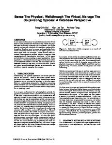
Figure 1: Multi-core cache memory hierarchy. be connected by a common bus. Moreover, even though the processors have their own private caches, current multi-core architectures often support a shared last level cache (shared across cores), as shown in Figure 1. Thus, any timing analysis framework for programs running on multi-cores needs to develop accurate timing models of the shared cache as well as the shared bus. To the best of our knowledge, this paper is the first work to develop a timing analysis framework that combines the timing effects of shared cache as well as shared bus. Conceptually, a combined analysis of shared cache and shared bus presents us with a challenging problem. To analyze the timing effects of a shared cache, we first perform separated cache analysis for the individual cores. Subsequently for each shared cache line, we find out the possible conflicts from the other cores, and calculate the cache hit miss classification accordingly. The key step here is to find out the shared cache conflicts across cores, which depends on the lifetimes of the tasks executing in the different cores (and whether these lifetimes overlap). Once the shared cache conflicts are determined, these are fed into the shared bus analysis. For the shared bus analysis, we consider static bus schedule using a Time Division Multiple Access (TDMA) scheme. The cores are assigned bus slots, and the bus slots are allocated among the cores in a round-robin fashion. By exploiting the static bus schedule and the shared cache conflict information, we can estimate the lifetimes of tasks on different cores. However, this creates opportunities for tighter analysis as we can rule out some of the shared cache conflicts by using the estimated task lifetimes. After ruling out cache conflicts, we have to again revise our shared bus analysis to get tighter task lifetimes. Thus, the interaction between the shared cache and shared bus analysis occurs iteratively and
both analyses get tightened via a fixed-point computation. Presenting such an integrated analysis framework to consider the timing effects of shared cache and shared bus is the main contribution of this paper. In the preceding, we have presented the big picture view of our contributions highlighting the conceptual novelties. In addition our timing analysis framework also presents several technical novelties that helps us develop a scalable and efficient analyzer. In particular, our shared bus analysis is compositional — each core is analyzed separately. This is achieved by mapping the memory accesses in each core i to specific bus slots which are allocated to core i. However, we cannot afford to map dynamic memory accesses to bus slots, as it would amount to full-fledged loop unrolling and path enumeration. Instead, we conservatively map the static memory accesses to bus slots by considering the computation time between two memory accesses and rounding up this computation time to the nearest multiple of the bus slot length. This presents us with a shared bus analysis framework that is simple, efficient, as well as accurate as evidenced by our experiments. In terms of experimental validation, we present results from independent non communicating tasks, as well as concurrent programs with communicating tasks. We compare our estimation results with estimation results from shared cache analysis (without bus modeling). More importantly, we have also developed a cycle-accurate simulation infrastructure for concurrent programs running on multi-cores. Our simulator is built on top of CMP-SIM [1], a simulator for chip multiprocessor architectures built on Simplescalar [2]. CMP-SIM allows for multi-processor architectures with shared cache but has no provision for shared bus. In our implementation, we have extended CMP-SIM with shared bus modeling thereby developing a cycle-accurate simulator for present day multi-core architectures. The experiments indicate that our estimation results are close to the simulation results — the over-estimation being around 20% for a large fragment of the real-life DEBIE program, an in-situ space debris monitoring program developed by Space Systems Finland Ltd [3].
2.
SYSTEM AND APPLICATION MODEL
Our system architecture is representative of the current generation of commercial multi-core platforms. Each core on chip has one or more levels of private caches and the last level of private caches from all the cores are connected to a large shared cache through a shared bus. For example, ARM Cortex-A9 MPCore [4] and Intel core 2 (code named Penryn) [5] have only private L1 caches that are connected via a bus to the shared L2 cache as shown in Figure 1 (Architecture A). The advantage of a shared cache is that the cache space can be dynamically and transparently allocated to the different cores based on their memory requirement. Next-generation multi-cores are likely to introduce more levels of private caches before hitting the shared resources. For example, Intel Xeon [6] has private L1 and L2 caches; the L2 caches are connected to a large shared 16MB L3 cache through a bus as shown in Figure 1 Architecture B. In this paper, we will assume, without loss of generality, the first architecture in Figure 1 (Architecture A) to develop WCET analysis of shared resources in multi-core platforms. Extending our work to multiple levels of private cache hierarchy is simply a matter of employing the same propagation
principle that we employ from L1 to L2 cache. We focus here only on the instruction memory. We assume that the data memory references do not interfere with the L1 and L2 instruction caches modeled by us (they could be serviced from a separate data cache that we do not model). We do not allow self-modifying code and hence do not need to model cache coherence. For each program, all shared library code used in it are copied into its private code section. Hence, there is no code sharing among different programs running in different cores. We consider Least Recently Used (LRU) cache replacement policy for set-associative caches. Also, we consider architectures without timing anomalies caused by interactions between caches and other architecture features. The L2 cache block size is assumed to be larger than or equal to the L1 block size. This is usually the case in real architectures to exploit higher spatial locality through a second level cache. Finally, we are analyzing non-inclusive multi-level caches [7]. The shared communication infrastructure in our architecture is the bus. It is used for accessing the instructions and data from the shared L2 cache (in case of L1 cache miss) by the different cores. However, as we are not modeling the data caches, we assume fully separated buses and memories for both code and data. Therefore, we ignore bus traffic arising from data memory accesses and this includes interprocess communication through shared memory. We assume TDMA-based static bus scheduling policy where a fixed length bus slot is allocated to each core in a roundrobin fashion. During WCET analysis, we assume all loop bounds are known through user annotation or simulation. We also assume all paths in a program are feasible and all loops in a program are reducible (i.e., all loops have a single entry and single exit). We model the application as a set of task graphs. Each task graph is a directed acyclic graph consisting of a number of tasks. Let {T0 , . . . , TN −1 } be the set of N tasks corresponding to all the task graphs. A directed edge between two tasks Ti and Tj in a task graph denotes that task Tj can start execution only after task Ti completes execution. Our objective is to estimate the worst-case response time (WCRT) of the overall application.
3.
OVERVIEW
Our WCRT analysis framework in the presence of shared cache and bus in multi-core platforms appears in Figure 3. L1 cache analysis proceeds independently for each core. The memory accesses that are guaranteed to be L1 cache hits are eliminated from further consideration at this point. The remaining memory accesses (guaranteed / probable L1 misses) can be transmitted via the bus and are considered for shared cache and bus analysis. Clearly, the bus analysis requires the time at which the L1 cache misses appear on the bus. However, the bus access time of an L1 cache miss is affected by the execution time of the preceding memory accesses in the same core. This in turn is determined by the shared L2 hit/miss categorization of the preceding memory accesses. On the other hand, the shared L2 cache conflict analysis determines the memory blocks that may get evicted by memory blocks from other core. Whether a memory block M 1 belonging to task T 1 can be evicted from the shared cache by a memory block M 2 from task T 2 depends on whether the lifetime of the
Core�0
Bus
Core�1 Core�0
Bus
T3.1=20 Core0 slot T1.1=90 1 M3.2�=20
T3.1=20 Core0 slot
Wait T3� lifetime
T1.1=�90 T1.1= 90
T3.1=�20 T3 1= 20 T3.1= T3.2=10
T2.1= 10 T2.1=�10 T2� lifetime
M3.2=10
T2.2=20 T2.1 10 T2.1=�10 T2.2=20
T4.1 20 T4.1=�20 T4.2=10
Core�0
Core�1
T4.1��=20 T2.1=�10
M2.2=20 Core0 slot
Wait
Wait
T1.1=90
T3.2�=�10 Core1 slot
Core�1
T2.2�=20
T3.2=10
Core1 slot
T4.1=20
M4.2=10 M2.2=10 M2 2 10
T4.2=10
Core0 slot
M4.2�=�10 T4.2��=10 Core1 slot
Core1 slot
L2�Hit:����10�cycles L2�Miss:�20�cycles M2.2�and�M3.2�conflict�in�L2:� Both�L2�Miss M4.2�is�L2�Hit
Bus�schedule�based�on�M2.2,�M3.2�L2�miss WCRT:�170�cycles T2�and�T3�have�Disjoint�lifetime M2.2�and�M3.2�cannot�conflict:�Both�L2�Hit
Bus�schedule�based�on�M2.2,�M3.2�L2�Hit Second�bus�wait�for�Core�1�eliminated WCRT:�130�cycles
(a)
(b)
(c)
Figure 2: Example to show dependency between cache and bus analysis.
L1�cache� analysis
L1�cache� analysis
Cache�access classification
Cache�access classification
L2�cache analysis
Initial�interference
L2�cache� analysis
L2�conflict� analysis Modified� interference
Bus�aware Bus aware WCET/BCET computation
WCRT computation
Estimated� WCRT
No
Interference changes�?
Yes
Figure 3: Our analysis framework two tasks can overlap or not. The task lifetime, in turn, is determined by the shared bus analysis results. This circular dependency between the bus and cache analysis requires us to develop an iterative analysis framework as shown in Figure 3. In the first iteration, we perform shared L2 cache analysis assuming that a task on one core can conflict with all the tasks in other cores. Based on this pessimistic L2 cache analysis results, we estimate the shared bus access time and hence the WCET of the different tasks. These numbers are fed to the WCRT analysis component that estimates the worst-case response time of the complete application by taking into account the dependencies among the tasks. A by-product of the WCRT analysis framework is
the lifetime of each task. These lifetime estimates are used to eliminate interference among tasks with disjoint lifetimes. If the interference pattern has changed (i.e., we have managed to eliminate some interferences), the shared L2 cache analysis has to be repeated. We can formally prove that our analysis monotonically reduces the task interferences across iterations, and hence is guaranteed to terminate.
Illustrative Example. We now show the working of our analysis using the example in Figure 2(a). We assume a 2core system where the task graph containing tasks T 1 and T 2 are running on core 0 and task graph containing tasks T 3 and T 4 are running on core 1. For simplicity of exposition, we shall assume in this example that best case and worst case execution times of any task are same. T 1.1, T 2.1, . . . , T 4.2 represent the memory blocks within the tasks. Each memory block is annotated with its computation cost. Only the memory blocks marked in black are the ones with guaranteed or possible L1 cache miss as determined by per-core L1 cache analysis. We perform an initial L2 cache analysis for each core individually that ignores conflicts from other cores. This per-core L2 cache analysis determines all the memory blocks (T 2.2, T 3.2, and T 4.2) as guaranteed L2 cache hits. Let us also assume that L2 cache hit latency is 10 cycles, whereas L2 cache miss latency is 20 cycles. Further, the round-robin TDMA bus scheduler assigns a 50 cycle bus slot to each core and the first bus slot goes to core 0. In this example, to demonstrate the dependency between shared cache and bus analysis, we ignore any cold cache misses. However, our analysis does not rely on that assumption and it accurately models the additional cycles due to cache misses if some memory blocks have to be loaded into the cache for the very first time. Now we proceed to shared L2 cache analysis. At this point, we have no information about task lifetimes. So we assume any task on core 0 can conflict with all the other tasks on core 1 and vice versa. Memory block T 2.2 and T 3.2 map to the same L2 cache block and therefore they conflict
with each other. So we have to conservatively assume that both of them will be L2 cache misses in the worst case, whereas T 4.2 remains as L2 cache hit because it does not conflict with any memory block from core 0. Note that, even though any task on core 0 can conflict with all the other tasks on core 1 and vice versa, memory block T 4.2 may not conflict with T 2.2 since it maps to a different cache block in shared L2 cache. After shared L2 cache analysis, we proceed to shared bus analysis. The result of the analysis can be visualized in Figure 2(b). In Figure 2, a memory transaction corresponding to the L1 cache miss of memory block P x.y is denoted by M x.y. Notice that all L2 cache accesses (whether hit or miss) are transmitted on the shared bus in our architecture. An L2 cache access from core i has to wait for core i to get access to the bus. The L1 cache miss M 2.2 in core 0 occurs at time 100. From the bus schedule, we can observe that the slot beginning at time 100 belongs to core 0. Thus M 2.2 does not encounter any additional waiting time to acquire the shared bus and is completed by time 120. Thus, T 2 finishes at time 140. However, the L2 cache miss M 3.2 in core 1 happens at time 20 and the bus slot from time 0 to time 50 is alloted to core 0. Hence, M 3.2 encounters an additional 30 cycles waiting time to acquire the bus and eventually the memory transaction corresponding to M 3.2 completes at time 70. This makes task T 3 to finish at time 80. Similarly, the L2 cache hit M 4.2 in core 1 occurs at time 100 and the bus slot from time 100 to time 150 is alloted to core 0. Thus M 4.2 encounters an additional 50 cycles waiting time and eventually the task graph running on core 1 is completed at time 170. Hence, the WCRT of the application according to this schedule is 170 cycles. However, as a by-product of the WCRT analysis, we note that task T 2 and T 3 have disjoint lifetimes. So memory blocks T 2.2 and T 3.2 cannot conflict with each other in the shared L2 cache and they remain as L2 cache hits as determined by per-core L2 cache analysis. As L2 cache hits have shorter latency, the bus analysis needs to be re-done. The revised schedule is shown in Figure 2(c). Task graph running on core 0 finishes at time 130 because M 2.2 is now a L2 cache hit. Due to the earlier completion of M 3.2 (because of L2 hit), L2 cache hit M 4.2 occurs at time 90. Since L2 cache hit latency is 10 cycles, M 4.2 can be serviced in the remaining bus slot belonging to core 1 (i.e., the bus slot from time 90 to time 100) and therefore making T 4 finish by time 110. Hence, this new analysis results in much tighter WCRT estimate as the second wait time for the bus in core 1 is now eliminated. The WCRT at this point changes to 130 cycles. This example illustrates how an iterative shared cache and bus analysis can obtain tight WCRT estimates for embedded real-time applications.
categorized as AM, it means that the instruction is never in the cache whenever it is accessed. Persistence analysis is carried out for increasing analysis precision. An instruction is persistent if it is never evicted from the cache. If an instruction cannot be categorized as one of AH, AM or PS, it is categorized as NC. For details of the analysis, readers are referred to [8]. Cache access classification (CAC): In multi-level cache hierarchies, a specific cache level may not be accessed at all. Thus access classification of a specified cache hierarchy must also be known [7]. For a given memory access r, CAC (Cache access classification) of a particular cache level L can be (i) A : this means that the cache level L will always be accessed (for cache level 1 this is always true), (ii) N : this means that the cache level L will never be accessed, or (iii) U : this means the access of the cache level L cannot be determined statically for memory access r. For example, consider a two level hierarchy with L1 and L2 instruction caches. It is clear that AH categorized instructions in L1 cache are never accessed in the L2 cache. On the other hand, AM categorized instructions in L1 cache are always accessed in the L2 cache. For the other two cache hit-miss categorizations (namely PS and NC), it is not clear whether the L2 instruction cache is accessed or not. Thus all possibilities must be explored for a safe solution. For further details readers are referred to [7]. Shared L2 cache analysis: Intra-core cache analysis does not consider interferences in the shared L2 cache across cores. Thus the hit-miss classification of the instructions in L2 cache may be underestimated and may lead to an unsafe WCET estimation. A recent paper [9] deals with the shared cache conflicts as follows: Suppose the abstract cache state (which consists of a number of abstract cache sets for set-associative caches) of L2 cache after the intra-core must analysis contains instruction I in the abstract cache set S at a certain program point p and hence classified as AH. Say I c is the set of instructions in programs running on all other cores which can potentially map to the same abstract cache set S in the shared L2 cache and the Cache access classification (CAC) is always/unknown (A/U) for L2 cache access. The cache conflict analysis changes the hit-miss classification of instruction I in shared L2 cache at program point p to not-classified (NC), if it was previously classified as AH and the following holds:
4.
4.2
4.1
ANALYSIS FRAMEWORK Background on cache analysis
Intra-core cache analysis: We use the abstract interpretation based approach as described in [8] for analyzing private instruction caches. Instructions are classified as allhit (AH), all-miss (AM), persistence (PS) or not-classified (NC) after carrying out three analyses, namely must, may and persistence analysis. If an instruction is categorized as AH, it means that the instruction is always in cache whenever it is accessed. On the other hand, if an instruction is
N − age(m) ≤ |M (I c )|
(1)
where N is the associativity of the shared L2 cache, age(m) is the age of memory block containing instruction I in the abstract set of L2 cache at program point p and |M (I c )| is the number of memory blocks containing the set of instructions I c . Details of the analysis appear in [9].
Bus-aware WCET analysis
We now present a bus-aware WCET analysis of programs. Note that L1 cache misses are transmitted via the bus to access the shared L2 cache (Fig. 1, Architecture A). Classical WCET analysis can compute the WCET of a program by taking into account only the number of worst case cache misses. The exact time-stamp of the cache misses (the time at which the cache misses occur) are not required for WCET computation. In presence of a shared bus, a cache miss encounters variable amount of delay due to the waiting time elapsed to acquire the bus-slot for the corresponding
Left�Branch
Common�Path
Right�Branch
t=0 C4�=�10 C4 10 0 M5=�10 C5�=�10 C5 10 C6 10 C6=��10
C2=�30 C1=�20
L2�Hit
C4=�10 C5=�10 C6=�10
C2=�30 C2 30 C3=�20
Iter1
Core0� Bus�slot
C1=10 C1 10 M2 10 M2=10 C2=10
t=50 Code Executing on Core0
L2�Hit
C1 10 C1=10 M2 10 M2=10 C2=10 C1 10 C1=10 M2=10 C2=10 C1 10 C1=10 M2 10 M2=10 C2=10
Iter1
Iter2
Core0� Bus�slot
Iter3
t=100
M3=�10 C3=�20
C7=�30 C8 10 C8=�10
t=0
C1=20
Code Executing on Core0
Core0� Bus�slot
C1=10 C1 10 C2=10
L2�Hit
t=100
M7=20
L L2�Miss
t=150 C7=30 C8 10 C8�=�10 Align
Bus�slot:��50�cycles,�L2�hit:�10�cycles, L2�miss:��20�cycles, Bus�slot�is�assigned�in�round�robin� fashion�between�2�cores. C1,C2,�….�,C8�are�memory�blocks�inside�loop� annotated�with�the�computation�cost.
t=200
C1=20
Iter2
C1=10
Core0� Bus�slot No�unrolling
(a)
C1=10
Iter4
Core0� Bus�slot
Partial�unrolling
(b)
Figure 4: (a) An example of loop analysis (b) Limited loop unrolling for loop iterations with low cost. core. One naive approach is to always consider the maximum possible waiting time for each memory reference that may potentially access the shared bus. In that case, effect of shared bus in WCET analysis can be ignored at the cost of obtaining highly over-estimated WCET value. Our analysis effectively bounds the over-estimation in WCET analysis, while keeping the analysis time-efficient. Formally, the round-robin TDMA bus schedule is represented by the following recurrence relation: (i+1)
CSk (i)
(i)
(0)
= CSk + B; CSk
= Ak
(2)
where CSk is the starting time of the bus schedule assigned to k-th core in i-th round, B = J × sl , J being the total number of cores, sl is the slot length assigned to each core and Ak is the starting time of the very first slot in the bus schedule assigned to k-th core. At first we discuss the WCET computation of a single loop (no nesting) and later we extend it to a full program. Analysis of loop is depicted by an example in Figure 4(a). The bus slot is 50 cycles. Let us also assume that L2 cache hit latency is 10 cycles, whereas L2 cache miss latency is 20 cycles. Only the memory blocks marked in black denote L1 cache misses and hence will be transmitted via the bus. The loop starts at 0 time. Following this assumption, L1 cache miss M3 occurs at time 50. Since the next bus slot for Core0 starts only at time 100, this L2 cache access is delayed till time 100. Thus total time encountered for M3 access becomes 60 cycles — 50 cycles to wait for the bus and 10 cycles to get the instruction from L2 cache. On the other hand, L1 cache miss M5 starts at time 30, when the bus is still available to Core0. As a result, M5 does not suffer any delay to access the bus. Worst case starting time of the loop sink node is at time 130. Once again, due to the availability of the bus, L2 cache miss M7 can be served immediately. Finally the computation of loop sink node ends at time 190. Since we always assume a loop iteration starts from the beginning of a bus slot of Core0, an alignment cost of 10 cycles is added to the total cost of one iteration. Assuming loop bound to be 5, overall WCET of the loop
becomes (5 ∗ (190 + 10) + 100) = 1100 cycles (additional 100 cycles were added for aligning the first iteration of the loop, since the time between the beginning of any two consecutive bus slots allotted to the same core is 100 cycles). Note that, an L1 cache miss, occurred earlier than the time predicted in the worst-case, is served by an earlier bus slot (than the bus slot predicted in the worst-case analysis). This accounts for the safety of our method. Formally, WCET computation of a loop is described in Algorithm 1. startbi and f inishbi keep track of the worst case starting and finishing time of basic block bi respectively. cost stores the worst case cost of basic block bi while bi is being processed. f inishbi is computed by adding the value of cost to startbi (line 30). Header node of the loop always starts from time 0 (line 5). Worst case starting time of any basic block (other than the header node) is the maximum of all of its predecessors’ finishing time (line 9). lbusbi is the beginning time of the latest bus slot acquired by the core while basic block bi is processed; this information is propagated to all successor basic blocks (line 10). For an L1 cache miss, function Wait computes the worst case additional delay for accessing the shared bus (line 18). W ait(Δ) =
⎧ � × B + sl − LAT ) >= Δ; ⎨ 0, if (� Δ B ⎩
� + 1) × B − Δ, otherwise. (� Δ B
Here Δ is the difference between the current time and lbusbi . sl is the bus slot length assigned to each core. LAT is equal to the fixed L2 cache hit latency in case of a L2 cache hit and main memory latency in case of a L2 cache miss. The � represent the number of full bus schedules (whose term � Δ B �×B length is equal to B) expired in time Δ. Therefore, � Δ B represents the starting time of the latest bus slot assigned to the core relative to lbusbi . Relative to lbusbi , end time of � × B + sl . On the other hand, this latest slot is at time � Δ B end time of the current L1 cache miss is Δ + LAT relative to lbusbi . To complete the current L1 cache miss in the latest � × B + sl ≥ Δ + LAT , bus slot, it must be the case that � Δ B which is precisely the first condition of W ait function. If the
Algorithm 1 WCET computation of a loop lp; B is the interval between two consecutive bus slots assigned to a core 1. costiter := 0; 2. for (all blocks bi of loop lp in topological order) do 3. cost := 0; 4. if (bi is the header node of loop lp) then 5. startbi := 0; /* assume loop header node starts at time 0 */ 6. lbusbi := 0; /* assume first bus slot starts at time 0 */ 7. else 8. find the predecessor pmax of bi having maximum finish time (f inishpmax ); 9. startbi := f inishpmax ; 10. lbusbi := lbuspmax ; 11. end if 12. inst := first instruction in basic block bi ; 13. repeat 14. if (inst is an L1 cache hit) then 15. cost := cost + L1lat ; /* L1lat : L1 cache hit latency */ 16. else 17. Δ := (startbi + cost) − lbusbi ; 18. if (Wait(Δ) > 0) then 19. lbusbi := startbi + cost + Wait(Δ); 20. end if 21. cost := cost + Wait(Δ) + LAT ; 22. end if 23. inst := next instruction in basic block bi ; 24. until (all instructions in basic block bi finish) 25. if (bi is the sink node of loop lp) then 26. Δ := (startbi + cost) − lbusbi ; 27. cost := cost + AlignCost(Δ); 28. costiter := (startbi + cost); 29. end if 30. f inishbi := startbi + cost; /* finish time of bi */ 31. end for 32. return costiter × N + B;
L1 cache miss at current time cannot be served in the latest bus slot, it is delayed till the next bus slot. Clearly, the � + 1) × B relative to lbusbi . next bus slot starts at time (� Δ B � + 1) × B − Δ precisely represents the waiting Thus (� Δ B time to acquire this next bus slot. In case a new bus slot is acquired (the second case in W ait(Δ) function), the value of lbusbi is updated (line 19). After computing the worst case cost of one iteration of the loop, the additional cost to align the next iteration to the starting of a bus slot is added to the WCET (by the AlignCost function) (line 27). AlignCost function is similar to the Wait function and is described as follows. AlignCost(Δ) =
⎧ ⎨ 0, if (Δ mod B) = 0; ⎩ (� Δ � + 1) × B − Δ, otherwise. B
Thus, if Δ is already aligned with the beginning of a bus slot alloted to the core, alignment cost is 0. Otherwise, alignment cost is equal to shift the timeline to the beginning of the nearest bus slot alloted to the core. By adding AlignCost(Δ) we get costiter , the worst case cost of one loop iteration. Since we do not know the exact starting time of the loop, for the very first iteration, maximum alignment cost needs to be added (which is equal to B). Hence, the WCET of the loop is computed as costiter × N + B, where N is the loop bound. There is a special case when the worst case cost of one loop iteration is much smaller than the bus slot length. In that
case, due to the alignment to the beginning of a bus slot after one iteration, overestimation in WCET may increase significantly. We always partially unroll such loops so that worst case cost of a single iteration of the unrolled loop exceeds one single bus slot. This situation is illustrated in Figure 4(b). The loop is unrolled three times as L1 cache misses (M2) from three consecutive iterations can be serviced in a single bus slot. Extension to full program So far, we have only discussed the WCET computation of a single loop. To extend our analysis to whole programs, we transform the program’s control flow graph by converting each innermost loop to a single “basic block”. The cost of each innermost loop is given by the pre-computed WCET. Using the innermost loop’s WCET, we get the WCET of loops at the next level of nesting. In this way, we can get WCETs of all the outermost loops in a program. The program can now be viewed as a DAG with all outermost loops converted to single basic blocks. Algorithm 1 can again be used to compute the WCET of the program with zero alignment cost. For programs containing procedure calls, the extension is straightforward. For each call instruction, the cost of the callee can be computed as mentioned above and will be added to the total cost of the corresponding basic block. Our analysis is context sensitive, i.e., procedure calls at different call sites are analyzed separately. In our actual implementation, the cache analysis module also handles different contexts of a loop ( i.e., Virtual Inlining and Virtual Unrolling (VIVU) approach [8]) and thus our shared bus analysis indeed can model different contexts of a loop. However, for simplicity of discussion, we describe only about the WCET analysis of a loop in a single context.
4.3
WCRT Estimation
In order to compute the WCRT of a task graph, we need to know the time interval of each task. The task ordering is imposed by the partial ordering given in the corresponding task graph. We use four variables EarliestReady(t), LatestReady(t), EarliestFinish(t), and LatestFinish(t) to represent the execution time information of a task t. For any task t, the earliest (latest) time when all of t’s predecessors in the task graph have completed execution, is represented by EarliestReady(t) (LatestReady(t)). Similarly, the earliest (latest) time when task t finishes execution, is represented by EarliestFinish(t) (LatestFinish(t)). Given a task t, its execution interval is EarliestReady(t) to LatestFinish(t). We consider a non-preemptive system. Let us assume, WCET(t) and BCET(t) denote the Worst-case Execution Time and Best-case Execution time of task t. For BCET computation, all NC classified instructions in L1 cache are considered to be L1 cache hit and all instructions that are AM classified in L1 cache and NC classified in shared L2 cache are considered to be shared L2 cache hit. BCET of all the tasks are computed after the shared L2 cache analysis. A task t can be ready only after all its predecessors Pred(t) in the task graph finish execution. So the following two equations hold: EarliestF inish(t) = EarliestReady(t) =
EarliestReady(t) + BCET (t) max EarliestF inish(t) u∈P red(t)
For a task t without any predecessor EarliestReady(t)=0. However, latest finish time of tasks is not only affected by its
predecessors but also by the set of tasks running on the same core whose execution interval may overlap (called peers) [9]. Let us call the set of tasks overlapping with t, and running on the same core by �tpeers . Since, our WCET analysis assumes that the tasks are aligned to the beginning of a bus slot, during LatestFinish time computation, this alignment cost needs to be considered. In the worst case, all of the peers of a task and the task itself may encounter maximum alignment cost (equals B). Thus the LatestFinish time is defined as follows: LatestF inish(t)
= +
LatestReady(t) + W CET (t) � W CET (tc ) tc ∈�tpeers
+
(|�tpeers | + 1) × B
|�tpeers |
represents the number of peers of task t. This Here approach keeps our framework highly modular since the WCRT computation can be carried out given the WCET and BCET values of each task t, and without knowing their worst/best case starting time. Finally WCRT of an application is defined as follows: W CRT = −
maxt (LatestF inish(t)) mint (EarliestReady(t))
that is, the duration from the earliest start time of any task to the latest completion time of any task. Our WCRT analysis framework is shown in Figure 3. Initially a task t� cannot overlap (that is, interfere) with a task t if and only if 1) task t� depends on t and vice versa by the partial order imposed from the task graph or 2) t and t� execute on the same core (by virtue of non-preemptive execution). After the WCRT analysis, new interference information is generated if two independent tasks which accounted for shared cache conflicts in the cache analysis are found to have non-overlapping lifetimes, that is, their [EarliestReady(t),LatestFinish(t)] intervals do not overlap. This new interference information is again fed to the shared cache conflict analysis module which may further tighten several tasks’ WCET in presence of shared bus. This process continues until the interference among all the tasks stabilizes. We state the following two theorems which guarantee the termination of our WCRT analysis technique. The proofs are omitted due to space constraints. Theorem 4.1. For any task t, its EarliestReady(t) and BCET do not change across different iterations of L2 cache conflict and WCRT analysis. Theorem 4.2. Task interferences monotonically decrease (strictly decrease or remain the same) across different iterations of our analysis framework (Figure 3).
5. 5.1
EVALUATION Experimental setup
We compile our benchmarks for SimpleScalar Portable instruction set (PISA)[2] – a MIPS like instruction set architecture. The individual tasks are compiled into SimpleScalar PISA compliant binaries, and their control flow graphs (CFGs) are extracted as input to the analysis framework. Each processor core has an in-order pipeline along with an instruction cache.
In order to experimentally evaluate the accuracy of our analysis results, we have built a cycle-accurate simulation infrastructure on top of the CMP-SIM simulator [1]. We have extended CMP-SIM in three ways. First, we extend CMPSIM to handle PISA binaries. Secondly, CMP-SIM models shared caches, but not shared bus across cores. We have extended CMP-SIM with shared bus modeling to provide a cycle-accurate simulator for present day multi-core architectures; we instrumented each L1 cache miss in the simulation to go through a round-robin TDMA based shared bus. Finally, the existing CMP-SIM simulator only allows simulation of independent programs, each running on a different core. We have extended CMP-SIM to simulate concurrent applications represented as task graphs. All experiments are performed on a 3 GHz Pentium 4 machine having 1 GB of RAM and running Ubuntu Linux 8.10 as the operating system.
5.2
Analysis of independent programs
First we analyze independent programs running on multiple cores. Later we present results from analyzing the task graph from a real-life space debris monitoring program. We have performed experiments both for two-core and four-core platforms with the following cache configuration: L1 cache hit latency = 1 cycle, L2 cache hit latency = 6 cycles and memory latency = 30 cycles. Each private L1 cache is direct-mapped and has a size of 1 KB with block size of 32 bytes. The shared L2 cache is 4-way associative and has a size of 2 KB with block size of 64 bytes. The shared bus connecting the different cores is TDMA based and is accessed by all the cores in a round-robin fashion. Each core has a bus slot length of 80 cycles. For analyzing independent programs running on different cores, we have chosen benchmarks from [10]. The set of benchmarks is described in Table 1. We have benchmarks with small/medium code size (e.g., matmult, fft) as well as large code size (e.g., statemate, adpcm). Also, our chosen set of benchmarks contain both single-path programs (e.g., matmult, jfdcint) and multiple-path programs (e.g., compress, statemate). We have chosen a long running program statemate as a representative to run on a single core (to increase the probability of interference in shared L2 instruction cache) and different combinations of other programs are run on other cores. For all experiments on 2-cores, the estimation results for program X (other than statemate) correspond to running X in one core and statemate in the other core. The reported results for statemate are the average of all the runs. For 4-core experiments we either run (edn, adpcm, compress, statemate) on the 4 cores, or we run (matmult, fir, jfdcint, statemate) on the 4 cores. The reported results for statemate are the average of what we get from running (edn, adpcm, compress, statemate) and (matmult, fir, jfdcint, statemate). Figure 5 demonstrates the precision of our analysis. The overestimation ratio in Figure 5 is computed by dividing the estimated WCET with the observed WCET. Observed WCET of the program is computed through simulation by running it on a few sample inputs and taking the maximum of these running times. Our analysis results are marked by “Our Approach” in Figure 5. To compare the effect of shared bus analysis in WCET estimation, we have also shown the overestimation ratio for an architecture without shared bus (shown by the bar “With-
Table 1: Description of Benchmarks used
5.3
Analysis of task graphs in DEBIE
To evaluate our WCRT framework we have analyzed a large fragment of a real life DEBIE program [3], an in-situ space debris monitoring program. The task graph for the fragment of DEBIE program is given in Figure 7. We consider a system with four cores. The number inside each task of the task graph shows the mapping of the tasks to the processor cores. Codesize of each task is given in Figure 7.
Lines of Code 163 375 879 285
6244 11965
219 276
13411 52618
508 1276
Maximum Bus Delay Our Approach
Without bus
Over-estimation of various analyses (2-core) 2.5 2 1.5 statemate
compress
fir
adpcm
edn
fft
jfdcint
1 matmult
Benchmarks Maximum Bus Delay Our Approach
Without bus
Over-estimation of various analyses (4-core) 2.5 2 1.5 statemate
compress
fir
adpcm
edn
1 jfdcint
out Bus” in Figure 5). Some of the cases show a decreased overestimation ratio (e.g., statemate in 4-core) in presence of shared bus. Note that observed WCET also increases in presence of shared bus. Therefore, a decreased overestimation ratio signifies that the overestimation is more due to the presence of other micro-architectural entities (i.e., pipeline, cache) than due to the shared bus. Due to the difficulty of analyzing the shared bus, an obvious solution is to always assume the worst case waiting time for bus access for every memory reference that may potentially access the shared bus. Overestimation introduced from this approach is also depicted in Figure 5 as “Maximum Bus Delay”. As shown, for reasonably large programs ( e.g., edn, fft, adpcm, statemate) the overestimation is excessive, making this approach not useful in practice. As shown in Figure 5, our analysis can produce tight WCET estimates. The average overestimation from our approach is around 40%. For single path programs (e.g., matmult, edn), the overestimation is within 35%. Figure 6 presents the over-estimation ratio of benchmark statemate in various analysis results (“Our approach”, “Maximum bus delay” as mentioned above) for different bus slot lengths. Figure 6 shows that the precision of our analysis depends on the bus slot length. However, the over-estimation is much tighter than the analysis which uses maximum bus delay for each bus transaction (“Maximum bus delay” approach). Figure 6 also shows clearly that our analysis is not tied with a particular bus slot length. We have also analyzed the sensitivity of our analysis framework with L1 cache size, L2 cache size and memory latency. To analyze the sensitivity of one micro-architectural parameter, we vary only that parameter and keep other micro-architectural parameters’ value same as in Section 5.2. Cache sizes are varied from 1 KB to 16KB and memory latency is varied from 10 cycles to 50 cycles. The average over-estimation is 35%, 40% and 40% over different L1 cache sizes, over different L2 cache sizes and over different memory latencies respectively (figures are not shown due to space constraints). Hence, we conclude that the reasonable over-estimation in our analysis is not tied to a particular micro-architectural configuration.
Bytes 3737 16028 26852 10563
matmult
compress statemate
Overestimation ratio
fft fir
Description Matrix multiplication Discrete-cosine transformation Adaptive pulse code modulation algorithm Implements the jpegdct algorithm together with other signal processing algorithms Fast Fourier Transform Finite impulse response filter (signal processing algorithms) Data compression program Automatically generated code by the STAtechart Real-time-Code generator STARC
Overestimation ratio
Benchmark matmult jfdcint adpcm edn
Benchmarks
Figure 5: Overestimation in WCET analysis For the experiments with DEBIE, private L1 caches are changed to 2-way associative, 2 KB caches and the shared L2 cache is changed to a 4-way associative, 8 KB cache. The reason for changing the above-mentioned parameters is the relatively large code-sizes of the tasks in the DEBIE benchmark. Without a larger instruction cache, both simulation and estimation encounter cache thrashing making it difficult to evaluate the accuracy of our analysis. For this reason the L2 cache size is increased to 8KB in these experiments. All other parameters (bus slot, cache line size, cache hit latency, cache miss latency) remain unchanged from the settings used in Section 5.2. The analysis results are shown in Table 2. The value simbus denotes the observed WCRT (maximum execution time obtained from cycle-accurate simulation on a few inputs in presence of shared cache and bus). The values wcrtmax bus delay and wcrtours denote the WCRT estimates taking the maximum bus delay for every bus access and WCRT estimate from our analysis respectively — all in presence of shared cache and bus. We observe that the overestimation coming through our analysis is only 22.9% when compared to the simulation results (compare wcrtours with simbus ). Our analysis is time-
simbus 50432
Our approach
Maximum bus delay
Sensitivity w.r.t bus slot length (2-core)
wcrtours 61997
Table 2: Results from DEBIE (×104 cycles)
2.4 Overestimation ratio
wcrtmax bus delay 192567
2.2 2
ilar to the one shown in Figure 8 where each processor has 2 cores.
1.8 1.6
Processor�0
1.4
Processor�1
1.2 Core�0 Core 0
1 40
50
60
70
80
Core�0 Core 0
L1 L1�
L1
….
TDMA slot length for round robin schedule (in cycles) Our approach
Maximum bus delay
Core�N Core N
L1
Core�N Core N
…. L1 L1�
Sensitivity w.r.t bus slot length (4-core) 2.2
Crossbar
Crossbar
Shared�L2
Shared�L2
Overestimation ratio
2 1.8 1.6 1.4
Shared�off�chip�Bus
1.2 1 40
50
60
70
80
TDMA slot length for round robin schedule (in cycles)
Off�chip� Memory
Figure 6: Sensitivity of WCET analysis with bus slot length main�tc (1)
main�hm (1)
main�tm (1)
main�hit (1)
main�aq (1)
main�su (1)
tc�test (3)
hm�test (4)
tm�test (1)
hit�test (2)
aq�test (4)
su�test (2)
Core
Task�name
Code�size (bytes)
Core
Task�name
Code�size (bytes) 56,960
1
main�tc
240
1
tm�test
1
main�hm
240
2
hit�test
10,776
1
main�tm
240
2
su�test
50,176
1
main�hit
240
3
tc�test
45,368
1
main�aq
240
4
hm�test
44,176
1
main�su
240
4
aq�test
44,128
Figure 7: DEBIE task graph and task sizes
efficient. The time to produce wcrtours is less than 1.5 minutes. This time includes the full analysis time – starting from intra-core analysis to the end of our iterative and combined shared cache and bus analysis.
6.
EXTENSIONS AND FUTURE WORK
Other multi-processor architectures: Our analysis can easily be adopted with minimal changes for other kind of architectures featuring shared cache and shared bus. For example, consider the multi-processor architecture shown in Figure 8. In this type of architectures, a processor chip has multiple cores (as shown by Core 0, . . ., Core N in Figure 8). Each core in the processor has an on-chip L1 cache and all cores share an on-chip L2 cache through a crossbar switch. There might be multiple processor chips in the architecture (as shown by Processor 0 and Processor 1) and they access the off-chip system memory through an off-chip shared bus. Intel’s dual-processor and dual core architecture [11] are sim-
Figure 8: A multi-processor architecture featuring on-chip shared L2 cache Our analysis framework can easily be tuned to work with the above mentioned architectures. Each core can still be analyzed separately to produce per-core analysis result. Later, the interference between all the tasks running on the same chip can be used in on-chip shared cache conflict analysis. However, we observe that only shared L2 cache misses appear in the off-chip bus. Therefore, only shared L2 cache misses encounter variable amount of latency. On the other way, our bus analysis has to be employed only for shared L2 cache misses (which is a subset of L1 cache misses) instead of all L1 cache misses. Applications using shared library: In our current implementation, all shared libraries are copied inside each task. However, our analysis can easily be extended with shared libraries as follows: first, a single shared memory block in L2 cache could be accessed by two independent tasks. In this case, these two accesses are not conflicting and both accesses are cache hits. However, our shared L2 cache conflict analysis will interpret these two accesses as conflicting and in the worst-case both accesses to this shared memory block (in two different tasks) will be estimated as cache misses. Our shared L2 cache conflict analysis can easily be changed to incorporate this information. Second, in presence of shared libraries, initial cache state of a task may contain some shared memory blocks left by its predecessor tasks. This initial cache state can be estimated by taking into account all possible dependencies imposed by the application task graph.
7.
RELATED WORK
For single core systems, analysis of cache behavior for Worst-case Execution Time (WCET) has been well-studied. These works study the cache behavior for uninterrupted execution of a single program on a single processing element. For single level private caches, one of the most widely
adopted methods is based on abstract interpretation [8]. Indeed, the private cache analysis in our framework builds on abstract interpretation. Extension of the timing analysis to multi-level private caches appears in [7]. For multi-tasking systems, cache analysis estimates the cache-related preemption delay (CRPD). CRPD quantifies the impact of cache sharing on the execution time of tasks in a single core with preemptive scheduling. CRPD analysis computes cache access footprint of both the preempted and preempting tasks (e.g., [12, 13]). In multiprocessing systems, tasks in different cores may execute in parallel while sharing memory space in the cache hierarchy. Tools for estimating private cache access time are presented, among others, in [14] and [15]. On modeling shared caches in multi-core platforms, there have been very few works so far [9, 16, 17]. The work in [9] is the first to consider dependencies between tasks in a task graph for shared L2 cache analysis. The overestimation of WCET analysis proposed in [16] was reduced via compile-time identification of single-usage blocks in [17]. In multi-processor, static timing analysis of bus-based communication have been studied in earlier works (e.g., see [18, 19]). However, these works analyze the bus behavior without considering the impact of caches. The recent work [20] analyzes bus behavior in the presence of private caches. This work observes that the cache misses in the individual cores leads to bus accesses, and depending on the bus schedule the time to service a cache miss can exceed the cache miss penalty. However, [20] does not consider shared caches, and its timing interaction with bus accesses. Moreover, analysis in [20] is time consuming due to the virtual unrolling of loops. Another recent work [21] suggests providing hardware support for predictable execution of concurrent programs on multi-cores.
8.
CONCLUSIONS
We have presented an integrated analysis framework that considers the timing interactions between shared cache and shared bus accesses. Ours is the first work to model the timing effects of both shared cache and shared bus in multi-core platforms. Our analysis is efficient and avoids virtual loop unrolling. Our analysis results are compared with cycleaccurate simulation results to evaluate the precision of our analysis. We have also shown that our analysis can be applied to similar multi-processor architectures and in the future, we plan to extend our analysis to include pre-emptive execution and shared libraries.
9.
ACKNOWLEDGMENT
This work was partially supported by NUS grants R252000-321-112 and R-252-000-416-112.
10.
REFERENCES
[1] S. Baldawa and R. Sangireddy. CMP-SIM: an environment for simulating chip multiprocessor (cmp) architectures. http://www.utdallas.edu/∼rama.sangireddy/CMPSIM. [2] Todd Austin, Eric Larson, and Dan Ernst. Simplescalar: An infrastructure for computer system modeling. Computer, 35(2):59–67, 2002.
[3] European Space Agency. DEBIE – First standard space debris monitoring instrument, 2008. Available at: http://gate.etamax.de/edid/publicaccess/debie1.php. [4] ARM. ARM Cortex-A9 MPCore processor. http: //www.arm.com/pdfs/ARMCortexA-9Processors.pdf. [5] G. Varghese et al. Penryn: 45-nm next generation Intel core-2 processor. In IEEE Asian Solid-State Circuits Conf., 2007. [6] S. Tam Rusu et al. A 65-nm Dual-Core Multithreaded Xeon processor with 16-MB L3 Cache. IEEE Journal Of Solid State Circuits, (1), 2007. [7] D. Hardy and I. Puaut. WCET analysis of multi-level non-inclusive set-associative instruction caches. In RTSS, 2008. [8] H. Theiling, C. Ferdinand, and R. Wilhelm. Fast and precise wcet prediction by separated cache and path analyses. Real-Time Systems, 18:157–179, 2000. [9] Y. Li et al. Timing analysis of concurrent programs running on shared cache multi cores. In RTSS, 2009. [10] WCET benchmarks. http://www.mrtc.mdh.se/ projects/wcet/benchmarks.html. [11] Intel. Intel Core-2 Duo Processor. http://www.intel. com/products/processor/core2duo/index.htm. [12] C.-G. Lee et al. Analysis of cache-related preemption delay in fixed-priority preemptive scheduling. IEEE Transactions on Computers, 47(6):700–713, 1998. [13] H. S. Negi, T. Mitra, and A. Roychoudhury. Accurate estimation of cache-related preemption delay. In CODES-ISSS, 2003. [14] S. Schliecker et al. Reliable performance analysis of a multicore multithreaded system-on-chip. In CODES-ISSS, 2008. [15] J. W. Lee and K. Asanovic. METERG: Measurement-based end-to-end performance estimation technique in QoS-capable multiprocessors. In RTAS, 2006. [16] J. Yan and W. Zhang. WCET analysis for multi-core processors with shared L2 instruction caches. In RTAS, 2008. [17] D. Hardy, T. Piquet, and I. Puaut. Using bypass to tighten WCET estimates for multi-core processors with shared instruction caches. In RTSS, 2009. [18] H. Kopetz. Real-time Systems Design Principles for Distributed Embedded Applications. Kluwer, 1999. [19] K. Tindell and J. Clark. Holistic schedulability for distributed hard real-time systems. Microprocessing & Microprogramming, 50(2–3), 1994. [20] J. Rosen et al. Bus access optimization for predictable implementation of real-time applications on multiprocessor systems-on-chip. In RTSS, 2007. [21] M. Paolieri et al. Hardware support for WCET analysis of hard real-time multicore systems. In ISCA, 2009.