electronics and programmable logic controllers (PLC) technology for automatic capping of bottles. KeywordsâAutomation, Bottle capping, Mechatronics,. PLC.
International Journal of Emerging Technology and Advanced Engineering Website: www.ijetae.com (ISSN 2250-2459, ISO 9001:2008 Certified Journal, Volume 7, Issue 10, October 2017)
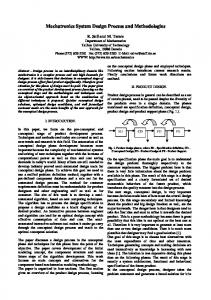
Modular Mechatronics System for Bottle Capping Shyam Sundar Padhy School of Automation, Banasthali University, Rajasthan-304022, India B. Sensors Sensors are the devices which measure the physical quantity and convert it to an electrical signal. We have used photoelectric sensor for detection of bottle and magnetic sensors in cylinders to know their position.
Abstract— This paper aims at the application of mechatronics in the capping of bottle in liquid beverage industries. We have developed a modular mechatronics system (MMS) which is a combination of pneumatics, electronics and programmable logic controllers (PLC) technology for automatic capping of bottles. Keywords—Automation, Bottle capping, Mechatronics, PLC
Sensors
Capping System
I. INTRODUCTION Mechatronics in a simple term can be defined as controlling the mechanical equipments by the help of electronics. Modular mechatronics system (MMS) is a flexible system which is a combination of emerging technologies mainly used in automation industries. Industrial automation playing a great role in the world which reduces the human work in production of goods and services. In this project we have used different technologies like pneumatics, sensors and PLCs to develop a compact and robust system that can be used in liquid beverage industries for automatic capping of bottles by reducing the human effort.
PLC
Compressor
Power Supply Unit Figure-1 Block Diagram
C. PLC Programmable Logic Controller (PLC) is a specialised computer which consists of microprocessor or microcontroller to control the electromechanical process. This is the central processing unit which receive signal from sensors and give the output signal to the capping system to complete the capping operation. We have used Siemens S7- 1200 PLC in this project.
II. METHODOLOGY We have designed a pneumatic capping system which will give signal to the sensors and then given to PLC as input. The output of the PLC is given back to the capping system to control the capping operation. The block diagram of the system is as shown in figure 1. The different blocks are as defined below.
D. Compressor An air compressor is used to give air supply to pneumatic capping system. Air is supplied through a FRL unit and pneumatic distributor to the directional control valves which moves the pneumatic cylinders.
A. Capping System The capping system is an electro-pneumatic system which performs the capping operation. It consist of conveyor belt unit for transporting bottles, pneumatic cylinders, directional control valves, pneumatic motor with bottle gripper, pneumatic distributor and FRL unit.
E. Power Supply Unit Power supply unit consists of switched mode power supply, MCBs, relays and conveyor motor driver unit. The entire system works on 24V DC. So the switched mode power supply converts 230VAC supply to 24V DC.
105
International Journal of Emerging Technology and Advanced Engineering Website: www.ijetae.com (ISSN 2250-2459, ISO 9001:2008 Certified Journal, Volume 7, Issue 10, October 2017) III. ITEMS REQUIRED We have used the following items which can be easily available in the market. Table- 1
Sl no
Items Name
1 2 3 4 5 6 7 8 9 10 11 12 13 14 15 16 17 18 19
Trolley with anodized profile plates Control console unit Switch mode power supply Miniature circuit breaker Relay Conveyor belt unit with brushless DC motor S7 1200 PLC Twin Rod cylinder with clamps Rod less Cylinder Pneumatic drilling motor Photo electric sensor 5/2 double solenoid DCV 5/2 single solenoid DCV Conveyor motor driver unit Terminal block interface unit Pneumatic distributor FRL unit Compressor Pneumatic pipes
Quantity in number 1 1 1 1 1 1 1 1 1 1 1 2 1 1 1 1 1 1 As required
Figure-2(a) Modular Mechatronics System
IV. PROCESS DESCRIPTION The bottles are placed on the conveyor belt and start push button is pressed on the control console which starts the conveyor motor. Photo electric sensor is kept to stop the bottle in the desired position for capping to take place. Twin rod cylinder with rubber pad extended to grip the bottle at the desired position. Pneumatic motor switches on and rod less cylinder comes down. The rubber pad attached to the pneumatic motor applies a force on the cap which is placed in the respective holder and capping is done. After some time the conveyor motor again switches on and the bottles are transported for further processing. All the above processes are controlled by using S7 1200 PLC. We have also provided emergency and reset button which can stop the process and reset it in case any fault occur in the capping operation. The modular mechatronics system and capping system is as shown in figures 2(a) and 2(b) respectively.
Figure-2(b) Capping System
V. PLC PROGRAMMING We have used Siemens Total Integrated Automation (TIA) portal software for programming. The ladder logic language is used to write the program. The entire program consists of eight networks as shown in figure 3.
106
International Journal of Emerging Technology and Advanced Engineering Website: www.ijetae.com (ISSN 2250-2459, ISO 9001:2008 Certified Journal, Volume 7, Issue 10, October 2017)
Figure-3(d) Network 4
Figure-3(e) Network 5
Figure-3(a) Network 1
Figure-3(f) Network 6
Figure-3(b) Network 2
Figure-3(g) Network 7 Figure-3(c) Network 3
107
International Journal of Emerging Technology and Advanced Engineering Website: www.ijetae.com (ISSN 2250-2459, ISO 9001:2008 Certified Journal, Volume 7, Issue 10, October 2017) VII. CONCLUSION Automation increases productivity and economy of a country. Our project can be implemented in soft drink industries of India. We have gained sufficient knowledge about pneumatics and PLC technology through this project. REFERENCES [1] [2]
[3]
Figure-3(h) Network 8
VI. FUTURE WORK The system is flexible in nature and this can be attached to a bottle filling system so that it can do the capping operation after filling. We are also planning to add a robot to the system which will pick the bottles after capping operation and place it in the cartons.
108
Shaukat .N, ―PLC based automatic liquid filling process‖, Multi Topic Conference 2002, IEEE publications. T. Kalaiselvi, R. Praveena, Aakansha .R, Dhanya, ‗‗PLC Based Automatic Water Bottle Filling and Capping System With User Defined Volume Selection‘‘ IJETAE, volume 2, Issue 8, August 2012 Mechatronics: Electronic Control Systems in Mechanical Engineering – by W. Bolton Pearson; 5 edition (7 November 2011)