The nist robocrane, a robot crane. Journal of Robotic Systems, July 1992. [2] Per Henrik Borgstrom, Nils Peter Borgstrom, Michael J. Stealey, Brett. Jordan ...
This is an author submitted version of the paper. For final version, please contact authors at
http://mrs.felk.cvut.cz
Motion Planning for a Cable Driven Parallel Multiple Manipulator Emulating a Swarm of MAVs Vojtˇech Von´asek
Martin Saska
Abstract— The Cable-Driven Parallel Multiple Manipulator is a supporting tool for development of control and navigation strategies of a swarm of Micro Aerial Vehicles (MAV). A crucial part of the system is a motion planning required to move the effectors representing individual MAVs to positions determined by a high-level algorithm controlling behavior of the swarm. Due to many degrees of freedom of such a system, finding feasible trajectories requires search in a high-dimensional configuration space, which is solved using a planner based on Rapidly Exploring Random Tree algorithm (RRT). To ensure fast planning for the multiple effectors, several novel expansion strategies of the RRT-based planner are discussed in the paper.
Libor Pˇreuˇcil
stop the motion of models of MAVs. Moreover, a particular experimental run can be repeated using this supporting tool to debug the algorithms. A crucial part of such a system is a motion planning module used to generate commands for the individual winches to move the MAV models to the desired positions in 3D space (see Fig. 1). Due to presence of several effectors in the same workspace, possible interactions among the effectors and the cables need to be considered in the planning process, which is addressed in the paper. II. R ELATED WORK
I. I NTRODUCTION & MOTIVATION Micro Aerial Vehicles (MAVs) have become very popular in various applications, such as inspection, search & rescue missions, surveillance, and many others. Nowadays, the research endeavor aims at development of approaches utilizing groups of autonomous MAVs closely cooperating together. Simple mechanisms for coordination and control of MAV teams working in laboratory indoor conditions are already available with impressive behavior [12]. Unfortunately, a big step ahead has to be done to be able to take such autonomous swarms of MAVs outside the laboratories. The biggest bottleneck rests in necessity of utilization of very precise and fast localization systems that have to be installed in experimental sites (e.g. the precise Vicon motion capture system used in [12]). The available global positioning systems (such as GPS) lack of sufficient precision for compact swarms of MAVs and suffer from signal lost in forest, urban, or indoor environments, which are especially appealing for MAVs deployment. An obvious solution could be to equip the swarm with an on-board relative localization system for stabilization of swarm members flying in a close proximity. It is inefficient and dangerous to test the algorithms with swarms of real MAVs especially in initial phases of the development. For the safe verification of the relative localization and swarming approaches, it is necessary to situate models of MAVs in positions required by the methods under development. For this purpose, a Cable-Driven Parallel Multiple Manipulator can be used, which allows fast positioning of the simulated MAVs and to slow down or even The authors are with Department of Cybernetics, Faculty of Electrical Engineering Czech Technical University in Prague, {vonasek,saska,preucil}@labe.felk.cvut.cz The work of V. Vonasek has been supported by the Ministry of Education of the Czech Republic under projects 7E11017 and by the EU under the project ICT-216342 and by the CTU grant No. SGS10/145. L. Preucil was supported by MSMT project Kontakt II no. LH11053. The work of M. Saska was supported by GACR under his postdoc grant no. P10312/P756.
Cable-driven manipulators are robots with effectors connected to the base frame by cables, which are driven using winches. In comparison with the conventional rigid-link manipulators, CDPMs bring a number of advantages, such as simple and light-weight mechanical structure, possibly high load capacity, large workspace limited by cable lengths and tension constraints, low moment inertia, high speed motion, and easy reconfigurability. CDPM are frequently employed for manipulation of heavy loads, aircraft simulators and testing system [20], [13], robotic rehabilitation systems [7], environment monitoring [2], cranes in shipbuilding [1] or camera positioning during sport and entertainment events (e.g. SkyCam and Cablecam systems), etc. The research endeavor in the field of CDPM is mainly focused on robots design, system analyses and trajectory tracking, which are crucial for current single CDPM applications. For example in [18], feasible workspace analysis for a single planar CDPM is provided. Optimal locations of connecting points and suspending points are investigated. An optimal force distribution was employed to obtain cable tensions to track a desired trajectory in [19]. Design, and kinematic and dynamic analyses of a CDPM for actuated sensing applications in nature are proposed in [2]. The work is focused on installation and calibration procedures, which enable rapid deployability of the system. A high speed CDPM is described in [10]. An internal force control among cables is employed to reduce vibrations of the robot. In [13], a CDPM platform is employed for simulation of the aircraft behavior in wind tunnels. Another application with cable driven robot acting as air vehicle simulator was presented in [20]. Both these approaches take advantage of the thin links (cables) of CDPM, which do not disturb streamline flow in wind tunnels. Similarly in simulations of MAV swarms, the links do not disturb the direct visibility between swarm particles, which is necessary for the visual relative localization.
In comparison to the above mentioned methods utilizing only a single CDPM, the simulation of MAV swarm requires more effectors operating in a common workspace. In such a Cable Driven Parallel Multiple Manipulator (CDPMM) each MAV is represented by a single effector. Here, the crucial part of the system is the motion planning method, which is used to generate trajectories to move the robots to desired configurations determined by a high-level strategy. The task of the motion planning is to find a feasible trajectory for the effectors between two given configurations while avoiding collisions with the cables, other MAVs and obstacles. The CDPMM robot is a system with many degrees of freedom (DOF), therefore sampling-based methods like Probabilistic Roadmaps [9] or Rapidly Exploring Random Trees [14] can be used to solve the motion planning problem. These methods solve the problem using sampling of the configuration space C of the system. A roadmap describing the free space Cf ree ∈ C is constructed by random sampling of C. The samples are classified as free or non-free using a collision detection. The free ones are stored into a roadmap, which is usually represented as a graph. Then, a motion in the workspace can be found as a path in the roadmap. The methods have been used in many applications including systems with many DOFs [21], [6], [16], [4]. The RRT algorithm is able to cope with both kinematic and dynamic constraints of the system [17]. Many modifications of the method has be designed such as RRT with goalbias [15] or RRT-Connect [11]. Several papers addressed the narrow passage problem [22], [8], [23]. A narrow passage is a small part of the configuration space and therefore, it is sampled with a low probability. If a resulting path needs to be found through the passage, many iterations is needed before the RRT samples the passage. In the case of CDPMM robot, the motion of the individual effectors is constrained mainly by the collisions between the cables and collisions with obstacles. As the purpose of CDPMM system is the emulation of swarm of MAVs, it is not expected to have scenarios with complex obstacles, therefore, the narrow passage issue does not need to be addressed. III. P RELIMINARIES Let q = (xi , yi , zi ), i = 1, . . . , M denote a configuration describing 3D position of M effectors in the global frame of the CDPMM system. The corresponding lengths of the cables can be derived from this position and position of its winches using inverse kinematics. The motion of the robots is controlled using control inputs u = (dxi , dyi , dzi ), i = 1, . . . , M , which define a displacement of the effectors. Size of both state q and input vector u is therefore 3M . Let umin , resp. umax denote maximal displacement of the robots. As the inputs define the displacement of the effectors, the new configuration of the system can be computed using motion model q˙ = u. The distance di (q1 , q2 ) is the Euclidean 3D distance between corresponding parts of the configurations q1 and q2 . The di (·, ·) therefore measures distance between the
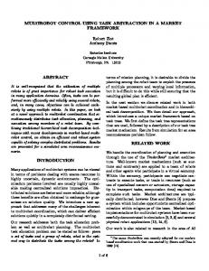
Fig. 1. Schema of the CDPMM robot with four effectors and its realization. The bottom picture shows the winches used in our prototype.
effectors in different configurations. The overall distance between two states PMis given as sum of the partial distances, ie., d(q1 , q2 ) = i=1 di (q1 , q2 ). IV. M OTION PLANNING
The proposed RRT-based planner works as follows. The algorithm iteratively builds a tree T of free configurations rooted at starting configuration qinit . In each iteration, a random sample qrand ∈ C is generated and the nearest node qnear ∈ T in the tree is found. Then, an expansion strategy is used to obtain a set S of configurations reachable from qnear . During the expansion, the motion model of the robot is used to obtain a new reachable configuration and its feasibility is checked using a collision detection. From the set S, the nearest configuration towards qrand is selected and added to the tree. The algorithm terminates if the tree approaches the goal configuration qgoal to a predefined distance. The algorithm is listed in Alg. 1. The performance of the RRT algorithm is influenced by two factors: the speed of collision detection and by the expansion strategy, which is discussed in the following sections. A. Expansion strategies The exploration ability of the RRT is caused by using several inputs ui ∈ U to generate the reachable configurations, where U is a set of combinations of input vectors. In the
[umin (i), umax (i)]; let Ri is either umin (i) or umax (i) with probability 0.5. a) Move randomly in one dimension: � ri i = j, ui (j) = i, j = 1, . . . , 3M 0 otherwise
Algorithm 1: RRT algorithm Input: number of iterations K, start and goal configurations qinit resp. qgoal Output: feasible trajectory or NULL 1 T .add(qinit ); 2 for iter=1:K do 3 qrand = random configuration; 4 qnear = T .nearestNode(qrand ); 5 S = expandState(qnear ); 6 if S 6= ∅ then 7 qnew = nearest state from S toward qrand ; 8 T .addNode(qnew ); 9 T .addEdge(qnear , qnew ); 10 end 11 if d(T.lastNode, qgoal ) < threshold then 12 return T .findPath(qinit , lastNode); 13 end 14 end 15 return NULL; // qgoal was not approached
Each ui moves only one effector at time and only in one direction. The displacement of the robot is defined by a random number ri . Number of generated inputs is 3M . b) Move by umin or umax in one dimension: � Ri i = j, ui (j) = i, j = 1, . . . , 3M 0 otherwise This type is similar to the previous one except the amount of the movement, which is either umin or umax . Number of generated inputs is 3M . c) Move all effectors randomly: ui (j) = (rj ),
expansion step (line 5 in Alg. 1), each input u ∈ U is applied to the motion model over time ∆t to obtain a configuration reachable from qnear . The expanded configurations are stored in the set S. Then, only a configuration nearest towards qrand is added to the tree. As the qrand is generated randomly in the C and the qnear is selected using nearest neighbor, the qrand attracts the tree towards unexplored areas of C [15]. The nearest neighbors are computed using the d(·, ·) metric defined above. In the case of mobile robots, the individual inputs can be discretized and the vector of input combinations U is then composed from all possible combinations of the discretized input. However, the number of combinations grows exponentially with the number of control inputs of the system. Each of the generated configuration needs to be checked for collisions. Therefore, generating many combinations of input vectors slows down the planning process. Moreover, the presented CDPMM system consists of several effectors emulating the MAV swarm. To examine how the effectors should be controlled, two types of expansion strategies to prepare the set U are proposed: Input* and Input-Line. In the former case, the set U is generated blindly to enable local exploration in the vicinity of the configuration qnear . Contrary to this approach, the latter one generates the set U according to a line connecting the configurations qrand and qnear . Let ui (j) is a j-th part of the vector ui . As a configuration describes 3D positions of the effectors, a control input ui moving the effectors on a line between two configuration q1 and q2 can be computed as ui (j) =
q1 (j) − q2 (j) . ∆t
(1)
1) Input* In this approach, the set U is generated to contain random input vectors. Let ri is a random number from uniform distribution in interval
i = 1, . . . M, j = 1, . . . , 3M.
As all the effectors are moved randomly at time, M inputs is generated. 2) Input-Line. In this approach, the U is computed to move the effectors on line L from qnear to qrand . Therefore, only one input vector is generated in this approach except the 2a subtype, which generates M input vectors. Again, we can define several subtypes, to determine how many and which robots are moved on the line. In the Input-Line approach, the control input ui are generated according to Eq. 1. a) Move one effector at time. For each robot i = 1, . . . , M , the vector ui moves only the i − th robot in all three dimensions, hence ui (j), ui (j + 1) and ui (j + 2), where j = 3(i − 1) + 1 is computed according to Eq. 1. b) Move all effectors simultaneously on the line L. Here, only one input vector u is generated according to Eq. 1. c) Move the effector with largest distance to qrand from qnear . In this case, only one effector is moved. This approach should ensure, that all the effectors explores the C similarly, i.e, no effector is significantly behind the others. d) Move the effector with largest distance to qgoal from qnear . Again, only one input vector is generated. However, only the effector with the largest distance from actual qnear to the goal is moved. e) Move the effector with largest distance from q ∈ T towards qgoal . Contrary to the previous approach, where an effector with the largest distance from qnear to qgoal is moved, in this approach, the distance from the goal is measured over all nodes in the tree. To maintain the largest distance between the tree and the goal for all the effectors, it is sufficient to update this distance after a new node is added to the tree. Therefore, this operation is not computationally intensive.
TABLE I N UMBER OF INPUT VECTORS GENERATED BY THE PROPOSED EXPANSION STRATEGIES . Strategy
1a
1b
1c
2a
2b
2c
2d
2e
Size of U
3M
3M
M
M
1
1
1
1
The expansion strategies defined above provide different number of input vectors, see Tab. I. While the Input* methods generate more inputs, most the Input-Line ones generate only one input vector. Therefore, the Input* strategies provide movements with higher resolution, which should increase the success of the methods. However, the expansion in the Input* strategies does not consider neither the current state of the tree nor the states of the robots. This is considered in the Input-Line strategies, where the global distance of the robots towards qrand or qgoal can be reflected. Important difference among the expansion strategies stands in the number of effectors moved at time. For a fast planning, moving all effectors simultaneously should be preferred. However, this could lead to a situation, where the configuration qnear cannot be expanded, because some of the effectors will be in a collision. However, moving only some of them could bring new reachable configurations. The efficiency of the proposed strategies is examined in the Section. V. B. Collision detection Usually, the collision detection is the most time consuming part of the sampling-based planners, as it is used during the expansion step to classify the expanded configuration as free or non-free and to check feasibility of an edge connecting two configurations. In the case of CDPMM robot, two types of collision detection need to be computed: a) to determine possible collisions between robots and obstacles and b) to determine possible collisions among the individual cables. In the former case, the collision detection can be implemented using plethora of methods [3]; in our case, the workspace is described using a 3D triangular mesh and the Rapid library [5] is used to perform the collision detection. To detect collisions between the cables, it is assumed, that the cables are stretched without any sag. Under this assumption, the cables can be represented as thin cylinders, using line segments or using thin triangles, which allows to use an analytic solution to check the collisions. The performance of these collision detection methods between the cables will be investigated in the experimental section. V. E XPERIMENTAL VERIFICATION The performance of the proposed RRT-based planner with different expansion strategies has been evaluated on the case of CDPMM robot with four effectors. Let RRTx , where x ∈ {1a, 1b, . . . , 2e}, denotes type utilized expansion strategy. A. Evaluation of the expansion strategies
The performance of the RRT planner with the proposed expansion strategies has been experimentally verified in three scenarios (Fig. 2). In the first scenario, called Sempty ,
Sempty
Sshort Fig. 2.
Slong
Testing scenarios.
an environment without obstacles was used, which allows to study the influence of collision detection between the ropes. In the second and third scenarios, called Sshort resp. Slong several short resp. long obstacles were placed into the workspace. As the purpose of the CDPMM robot is to simulate behavior of a MAV swarm, it is expected that the robots move between various positions in the environment. To emulate this behavior, a set T 0 = {(si , gi0 )}, i = 1, . . . , 100, of random and feasible start/goal pairs si , gi0 ∈ Cf ree was generated in all scenes. A randomly generated start/goal pair was added to T 0 only if both si , gi0 were collision free. This way of generating the pairs cannot ensure the reachability of gi0 from si . Therefore, for each pair (si , gi0 ) ∈ T 0 , the RRT2b planner with K = 15000 iterations was run to find a solution from the starting configuration si to gi0 . The nearest states gi towards the goal gi0 was found in the resulting tree. This allows to generate a set T of feasible and reachable start/goal pairs T = {(si , gi )}, i = 1, . . . , 100, which was used in the following experiments. For each start/goal pair, all the expansion strategies RRTx were run for 20 trials. The algorithms were run with goal bias pg = 0.1 (see [15] for details) and K = 5000 iterations. The measured values of runtime and size of the built trees were measured and averaged over the 20 trials. The quality of the solution is measured as ratio of effectors which reached the goal to a predefined distance over number of all effectors, which is called approach ratio ra . Although other quality metrics can be used, such a the trajectory lengths or time needed to traverse the trajectory, the proposed ratio ra shows the reliability of the tested planners. Again, the ra was averaged over the 20 trials for each start/goal pair. Therefore, the performance of the algorithm was described by three variables (avg. runtime, tree size and ra ) for 100 start/goal pairs. These 100 numbers are shown as boxplots with highlighted median on the graph depicted on Fig. 3. This allows to show the distribution of average performances over a range of start/goal pairs. The experiments have shown significant differences between the Input* and Input-Line expansion approaches. The planners with the Input* strategies (1a,1b and 1c) are significantly slower than the Input-Line strategies, which can be seen on the Fig. 3. This is caused by the number of reachable states examined in each iteration. While the Input* strategies generate up to 3M combinations of input vectors, the Input-Line strategies generate only one input vector, therefore medians of their runtimes are less than 0.5 s. The only one exception is the 2a strategy, which generates M input vectors. Therefore, it is slower than the rest of Input-
7
100
Slong Sshort Sempty
5500
5000
6 4500
80
4000
5
3500
Tree size
ra [%]
RRT time [s]
60 4 3000
2500
3 40 2000 2
1500 20
1000
1 500
0
0 1a
1b
1c
2a
2b
2c
2d
2e
Runtime
0 1a
1b
1c
2a
2b
2c
2d
2e
1a
ra ratio Fig. 3.
1b
1c
2a
2b
2c
2d
2e
tree size
Performance of the expansion strategies in the tested scenarios.
Line methods. The difference between the runtimes of Input* and Input-Line strategies can be seen in all three scenarios. Although the Input* strategies are slower, they have higher resolution and therefore, they are able to reach the goals more frequently, which is indicated by a higher ra ratio depicted on Fig. 3. Here, the strategies 1a and 1b found solutions for more than 50% of robots in all three scenarios. Regarding the ra metric, the best Input-Line strategy is the 2a on all three maps and 2b on the Sempty scenario; however, its ra ratio is decreased in the scenarios with obstacles. The experiments have also shown, that there is no significant difference between the runtimes of 2b, . . . , 2e InputLine methods. Although they differ in the ra measure, the deviation is so high, that we can conclude that their performance is similar over all three scenarios. The compromise between the Input* and Input-Line strategies is the 2a strategy. As this strategy generates M input vectors according to the line connecting qnear and qrand by moving only robot at time, there is higher chance, that the qrand will be approached in each iteration, which increases the reliability of the method. Moreover, the growth of the tree is attracted directly towards the qrand , which increases the exploration of the configuration space and consequently, it increases the speed of the 2a method in comparison to the Input* strategies. Note, that the 2a strategy is significantly faster than the 1c strategy, although both of them provide M input vectors. Examples of the trees generated by the expansion strategies in the Sshort scenario are depicted on Fig. II. B. Collision detection The speed of the collision detection has been evaluated using the RRT2b planner over 1500 queries defined in the set T . Two types of collision detection between the cables were used: a) triangle-based collision detection CDR4 , where each cable was represented by a single triangle, and b) segment-based collision detection CDRSegment , where the
cables were represented as lines. In the CDR4 case, the Rapid library was used to compute the collisions. In the latter case, two cables are in collision, if their shortest distance is less than 1 cm. Mean time of triangle-based collision detection is t¯ = 509 · 10−3 with deviation σ = 2.6 · 10−3 , the computation times for segment-based collision detection are t¯ = 27 · 10−3 , σ = 3.5 · 10−3 . Although the Rapid library with hierarchical collision detection was used in the CDR4 , the naive approach evaluating the collisions using the segments is significantly faster. Usually, the libraries for the triangle collision detection use a hierarchical data structures for speeding up the collision detection [3]. In such a structure, several triangles can be grouped together and described using a bounding box. The collision detection is then performed only on such nodes of the collision tree, whose bounding boxes overlap. However, as the cables of individual robots are anchored close to each other, the bounding boxes of the individual cables always overlaps. Therefore, the whole hierarchy need to be traversed, which slows down the collision detection. We can conclude, that for the purpose of collision detection between the cables, the naive computation of distance between two lines is sufficient enough. VI. C ONCLUSION We have presented a motion planning algorithm for a novel Cable-Driven Parallel Multiple Manipulator (CDPMM) utilized as a tool supporting development of localization and navigation methods for a swarm of MAVs. In our case, the behavior of the swarm is controlled using a bio-inspired techniques requiring realization of MAVs motion between various places in the environment. For this purpose, a fast and reliable motion planner based on RRT algorithm has been proposed. The performance of the planner is influenced by a way of generating the input vectors. For the CDPMM robot, where a configuration describes 3D position of the effectors, two general methods can be used to move the effectors:
1a
1c
2a
2b
TABLE II E XAMPLES OF THE TREES IN THE Sshort SCENARIO GENERATED BY THE 1 A ,1 C ,2 A AND 2 B EXPANSION STRATEGIES .
move it using a predefined set of inputs or move on line towards the random states. The experiments have shown that the Input-Line 2a approach provides fast motion planning and in the same acceptable ratio ra . The speed of the RRTbased planners is also influenced by the type of collision detection used to detect free configurations. Based on our experiments, it is efficient to detect the collisions among the cables by computing their distances. R EFERENCES [1] J. S. Albus, R. V. Bostelman, and N.G. Dagalakis. The nist robocrane, a robot crane. Journal of Robotic Systems, July 1992. [2] Per Henrik Borgstrom, Nils Peter Borgstrom, Michael J. Stealey, Brett Jordan, Gaurav S. Sukhatme, Maxim A. Batalin, and William J. Kaiser. Design and implementation of nims3d, a 3-d cabled robot for actuated sensing applications. Trans. Rob., 25(2):325–339, April 2009. [3] Christer Ericson. Real-Time Collision Detection. Morgan Kaufmann Publishers Inc., San Francisco, CA, USA, 2004. [4] R. Gayle, S. Redon, A. Sud, M.C. Lin, and D. Manocha. Efficient motion planning of highly articulated chains using physics-based sampling. In ICRA 2007. [5] S. Gottschalk, M. C. Lin, and D. Manocha. OBBTree: a hierarchical structure for rapid interference detection. In Proceedings of the conference of Computer graphics and interactive techniques, pages 171–180, New York, USA, 1996. Also available at: http://gamma.cs.unc.edu/OBB/. [6] L.J. Guibas, C. Holleman, and L.E. Kavraki. A probabilistic roadmap planner for flexible objects with a workspace medial-axis-based sampling approach. In IROS 1999. [7] K. Homma, O. Fukuda, Y. Nagata, and M. Usuba. Study of a wiredriven leg rehabilitation system. In Intelligent Robots and Systems, (IROS 2004), volume 2, pages 1668 – 1673 vol.2, 2004. [8] L. Jaillet, A. Yershova, S.M. La Valle, and T. Simeon. Adaptive tuning of the sampling domain for dynamic-domain RRTs. In IROS, pages 2851 – 2856, 2-6 2005.
[9] Lydia E. Kavraki, Petr Svestka, Jean-Claude Latombe, and Mark H. Overmars. Probabilistic roadmaps for path planning in highdimensional configuration spaces. IEEE Transactions on Robotics and Automation, 12:566–580, 1996. [10] S. Kawamura, W. Choe, S. Tanaka, and S.R. Pandian. Development of an ultrahigh speed robot falcon using wire drive system. In ICRA, volume 1, pages 215 –220 vol.1, may 1995. [11] James J. Kuffner, Jr. Steven, and M. Lavalle. Rrt-connect: An efficient approach to single-query path planning. In ICRA, 2000. [12] Alex Kushleyev, Daniel Mellinger, and Vijay Kumar. Towards a swarm of agile micro quadrotors. Robotics: Science and Systems, July 2012. [13] P Lafourcade, M. Llibre, and C. Reboulet. Design of a parallel wiredriven manipulator for wind tunnels. In Workshop on Fundamental Issues and Future Research Directions for Parallel Mechanisms and Manipulators, pages 187–194, 2002. [14] S. M. LaValle. Rapidly-exploring random trees: A new tool for path planning, 1998. TR 98-11. [15] S. M. LaValle. Planning Algorithms. Cambridge University Press, Cambridge, U.K., 2006. Available at http://planning.cs.uiuc.edu/. [16] S.M. LaValle, J.H. Yakey, and L.E. Kavraki. A probabilistic roadmap approach for systems with closed kinematic chains. In ICRA 1999. [17] Steven M. LaValle and James J. Kuffner Jr. Randomized kinodynamic planning. I. J. Robotic Res., 20(5):378–400, 2001. [18] C. B. Pham, S. H. Yeo, and G. Yang. Workspace analysis and optimal design of cable-driven planar parallel manipulators. In RAM, 2004. [19] Wei-Jung Shiang, D. Cannon, and J. Gorman. Optimal force distribution applied to a robotic crane with flexible cables. In ICRA, 2000. [20] K. Usher, G. Winstanley, and R. Carnie. Air vehicle simulator: an application for a cable array robot. In ICRA, 2005. [21] Vojtech Von´asek, Karel Kosnar, and Libor Preucil. Motion planning of self-reconfigurable modular robots using rapidly exploring random trees. In TAROS, pages 279–290, 2012. [22] Anna Yershova and L´eonard Jaillet. Dynamic-domain RRTs: Efficient exploration by controlling the sampling domain. In ICRA, 2005. [23] Liangjun Zhang and D. Manocha. An efficient retraction-based RRT planner. In IEEE International Conference on Robotics and Automation, pages 3743 –3750, 19-23 2008.