Multi-Bit Sigma-Delta Modulators with Enhanced Dynamic-Range using Non-Linear DAC for Hearing Aids J. R. Custódio, N. Paulino, J. Goes
Erik Bruun
Universidade Nova de Lisboa/UNINOVA Campus da FCT/UNL 2829-717 Caparica, PORTUGAL
[email protected]
Department of Electrical Engineering DTU - Technical University of Denmark, bldg. 349 DK-2800 Kgs. Lyngby, DENMARK
[email protected]
Abstract— This paper presents the possibility of employing nonlinear low-resolution DACs in the feedback paths of multi-bit second-order Sigma-Delta modulators. The proposed technique is particularly attractive in applications such as hearing aids, requiring a very large dynamic range and medium signal-tonoise-plus-distortion-ratio. As demonstrated through simulated results in which noise and mismatch effects are included, for the same over-sampling ratio, improvements in the order of 6-to-9 dB in the dynamic range can be achieved when comparing with the same topology employing linear-DACs.
I.
INTRODUCTION
Hearing aid circuits should work with a power supply voltage as low as 0.9 V and dissipate a very small amount of power to preserve the battery. In order to match the human auditory system, a very large dynamic range (DR) is needed for the signal processing path, including the ADC, but the signal-to-noise ratio need not be as high as the DR [1]. Essentially, this means that a larger noise level can be tolerated when large signal amplitudes are applied compared to the situation where a small signal amplitude is applied. This can be achieved by shaping the quantization error in the ADC as a function of the input signal amplitude. By using such a shaping, the system need not be designed for very low noise over the entire input voltage range and since low noise in general leads to more power consuming systems (e.g. due to higher over-sampling rate), such a noise trade-off can reduce the overall power consumption of the ADC. In this work we consider a data converter architecture aiming at a DR of 96 dB, corresponding to a resolution of 16 bits, while having a signal-to-noise-plus-distortion-ratio (SNDR) of the order of 60 dB. The signal bandwidth is approximately 20 kHz. The ADC used in hearing aid systems does not need to have a high linearity (an ADC with a linearity of 10 bits would suffice), so a trade-off between linearity and dynamic range is possible. The ADC can be implemented using a sigma-delta (Σ∆) modulator (Σ∆M) followed by a digital decimation filter. This approach is particularly attractive for signals with a small bandwidth because a large over-sampling ratio (OSR) can be used to obtain a high SNR value. However, in this application, it is important to keep the sampling frequency as low as
978-1-4244-2182-4/08/$25.00 ©2008 IEEE.
possible in order to reduce the power dissipation. This means that either a third or fourth order modulator or a multi-bit second order modulator should be used [2, 3]. The first option can be difficult to implement because of gain mismatch problems in multi-stage noise-shaping (MASH) architectures (which require opamps with high DC gain). Additionally, the second option normally requires the use of dynamic element matching to enhance the linearity of the DACs in the feedback-loop path [2]. However, using advanced CMOS technologies it is possible to obtain matching errors among capacitors at the 10 bit level and, therefore, the SNDR specification can be met without using any dynamic element matching techniques. Using a 4-bit second-order Σ∆M with an OSR of 64 it is possible to obtain the required peak SNR value [4]. This modulator is simpler than a MASH modulator and it also requires a simpler digital filter. In order to obtain the same DR, while reducing the OSR, it would be necessary to increase the resolution of the quantizer in the second-order Σ∆M. This would result in a more complex DAC in the feedback path of the modulator. In the case of using a 4-bit quantizer, it becomes necessary to use two DACs with 16 levels in the feedback path, but if the quantizer resolution is increased to 5 bits, it would be necessary to use two DACs with 32 levels in the feedback path. The 5-bit DAC improves the SNR because it has a lower LSB voltage than the 4-bit DAC and thus it has a lower quantization noise power. However, designing quantizers with more than 4 bits of resolution becomes a difficult task due to the low offset voltages required to the comparators, since low current consumptions are envisaged. In order to increase the DR, it is only necessary to improve the SNR for input signals with low amplitudes. Therefore, as we propose for the first time in this paper, the DAC can have a non-linear transfer function with a smaller LSB voltage for signals with small amplitude and a larger LSB voltage for signals with large amplitude. In the first case, the SNR is improved and, in the second case, the SNR is degraded. Using a non-linear transfer function in the DAC causes distortion but as long as it remains below the specification, it is acceptable. A multi-bit second order modulator using non-linear DACs in the feedback path can extend its DR without increasing the
1107
Authorized licensed use limited to: UNIVERSIDADE NOVA DE LISBOA. Downloaded on July 07,2010 at 13:06:29 UTC from IEEE Xplore. Restrictions apply.
resolution of the quantizer or increasing the OSR, allowing obtaining a Σ∆M with both lower sampling frequency and lower complexity. Alternative techniques to extend the DR have been proposed in [5, 6], based on non-uniform [5] or semi-uniform [6] quantizers. In the approach described in this paper, the quantizer is uniform but the DAC is non-linear, leading to an increased DR. The implementation of a non-linear DAC is easier than the implementation of a non-linear quantizer in standard CMOS because of less stringent component matching requirements than the ones explained in [6]. Thus, the approach described in this paper has some advantages in practical aspects, namely reduced spread and better matching in the capacitance values, since they can be laid out together in the same capacitor-array. From a study of many different nonlinear functions, two different functions have been selected for the following analysis to efficiently implement the non-linear DACs. This paper is organized as follows: in Section II, the architecture of the second-order ∆ΣM modulator is presented and the idea behind the proposed technique is explained. Section III shows the details of the design of the non-linear 4bit DAC in the feedback path to obtain “compression” at the modulator output. Section IV presents the simulation results obtained in Matlab/Simulink for the proposed ∆ΣM with linear and non-linear DACs. Finally, in Section V, some conclusions are drawn from the simulation results. II.
PROPOSED ARCHITECTURE
The proposed architecture is a 4-bit second-order ∆Σ modulator, as shown in Fig. 1. The modulator is constituted by two switched-capacitor integrators, a 4-bit linear flash ADC followed by a digital look-up table and two non-linear 4-bit DACs also implemented using a switched-capacitor approach.
DAC to the output of the ADC. This is achieved using a digital look-up table with 16 positions. The non-linear transfer function in the DACs is used to change the LSB voltage of the modulator, so that when the input signal amplitude is small, the LSB voltage is small resulting in a small quantization power. The DAC must have small steps for input codes close to the middle-scale code and larger steps for small and large input codes in order to cover the same range as a linear DAC. This is schematically illustrated in Fig. 2. The non-linear transfer function allows lowering the quantization noise power for small amplitude input signals; this means that the DR is extended. Of course the SNR is defined as the ratio between the signal power and the noise power comprising both quantization noise and thermal noise.
Figure 2. Conversion steps for a linear and a non-linear DAC
Therefore, there is limit to the possible extension of the DR, set by the thermal noise power. For large amplitude signals, the DAC transfer function has larger steps, corresponding to a larger quantization noise power, thus the peak SNR is expected to be lower. In this case the non-linear transfer function also adds distortion to the input signal, therefore lowering the SNDR of the modulator. The overall expected effect of the non-linear DAC in the SNDR of the modulator is shown in Fig. 3 for both, linear and non-linear DACs.
Figure 1. Second-Order Σ∆ modulator with a Non-Linear DAC.
In simple terms, a Σ∆ modulator works by having a negative feedback path that subtracts the quantized output of the modulator from the input signal. This subtraction is followed by a block with a large gain value inside the band of the signal. If the modulator is not saturated (which is the case in a stable modulator with an input signal below the reference voltage) the difference between the input signal and the quantized output is almost zero [3]. This means that the output of the DAC tracks the input signal, but since the DAC has a non-linear transfer function, this means that the DAC input is a distorted version of the input signal. In order to obtain a digital representation of the signal without the DAC distortion it is necessary to apply the same non-linear function of the
Figure 3. Expected SNDR for a Non-Linear DAC and Linear DAC.
The previous figure shows that the SNR should improve for signals with small amplitude, thus extending the DR of the modulator. On the other hand, there will be degradation in the SNDR for large amplitude signals. III.
DESIGN OF THE NON-LINEAR 4-BIT DAC
As previously mentioned the modulator should work with a supply voltage as low as 0.9 V. This low value limits the maximum signal excursion in the circuit. Considering that the amplifiers inside the integrator circuits are capable of having a
1108 Authorized licensed use limited to: UNIVERSIDADE NOVA DE LISBOA. Downloaded on July 07,2010 at 13:06:29 UTC from IEEE Xplore. Restrictions apply.
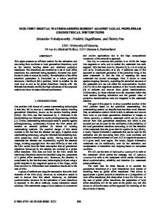
The non-linear function in DAC must provide a smooth transition between the smaller conversion steps in the center to the large conversion steps in the end of the characteristic. Several mathematical functions can be used: arctangent (atan(x)), hyperbolic arctangent (atanh(x)) and the sigmoid(x)=1 / (1+exp(–x)). After running simulation of the modulator with these different functions and analyzing the results, the selected function for the DAC is atanh(x). The output voltages of the 4-bit DAC are determined by this function. In order to try to improve the performance of the modulator a second type of non-linear function was used. This function called ze2(x) is obtained by adjusting each 4-bit DAC output voltage level independently from the others voltage levels. The 4-bit DAC transfer functions obtained using these functions, together with a linear characteristic are shown next in Fig. 4.
quantizer, a digital look-up table, containing the same values as the 4-bit DAC transfer function, is also used to obtain the output digital signal. IV.
SIMULATION RESULTS
The 4-bit second-order modulator using two non-linear DACs was modeled at high level. This model assumes that the integrators are ideal, that the 4-bit quantizer is ideal, but it allows including mismatch errors in the capacitance values in the 4-bit DACs. These mismatch errors are generated randomly with a standard-deviation (σ) that depends on the capacitor value. The smaller capacitors have maximum errors of σ=2% and the larger ones a maximum error of σ=0.2%. The model also includes thermal noise in both integrators. The modulator was simulated applying a sine-wave signal to the input and calculating the SNDR value of the modulator output. This procedure was repeated for different amplitudes of the input signal and, at the end, a plot of the SNDR as a function of the input amplitude is obtained. This simulation was performed in three different modulators: one with non-linear 4-bit DACs using the atanh(x) function, one using the ze2(x) function and, finally, one with the conventional linear 4-bit DAC. These three modulators were simulated for the ideal case (without mismatch) and considering mismatch. The OSR of the modulator is equal to 32 in all cases. SNDR vs DR (without Mismatch) 100 Linear: ID NonLinear: Ze2 NonLinear: Atanh
80
60
SNDR [dB] OSR= 32
single-ended signal swing equal to 0.375 V (leaving a safety margin of approximately 265 mV from both ground and positive power supply node), it is possible to have a differential signal swing equal to 0.75 V. Therefore, the reference voltage of the modulator is set to 0.75 V (this value can be changed later after the electrical design of the amplifiers). Assuming that the modulator overloads for input signals with amplitude 2 dB below the reference voltage, the total noise in the modulator must be below 6.7 µVrms in order to achieve the desired DR performance. This total noise power must include both the quantization noise and the thermal noise. The quantization noise of a 4-bit modulator with an OSR equal to 32 has a quantization noise level equal to 20 µVrms, which is larger than the specification. Assuming that a non-linear DAC is used and that the smallest conversion steps are equivalent to the steps in a 6-bit linear DAC, the quantization noise voltage can be lowered to 5.2 µVrms. This leaves a maximum of 4.2 µVrms for the thermal noise level in the modulator in order to keep the total noise below the desired noise level.
40
20
0
-20
DAC Linear: (.), Non-Linear: ze2 (*), atanh (+) 0.8 Linear Non-Linear: ze2 Non-Linear: atanh
0.6
-40 -120
-100
-80
-60 -40 Voltage DR [dB]
-20
0
20
0.4
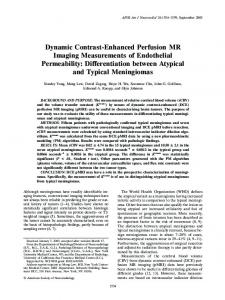
Figure 5. SNDR graphs of three modulators using linear 4-bit DACs and non-linear 4-bit DACs with different functions.
Vout [V]
0.2
SNDR vs DR (without Mismatch)
0
15 Linear: ID NonLinear: Ze2 NonLinear: Atanh
-0.2 10
-0.4 5
-0.8 0
2
4
6 8 10 Din [Thermometer Code]
12
14
SNDR [dB] OSR= 32
-0.6
16
0
Figure 4. 4-bit DAC transfer functions for 3 different cases.
-5
The 4-bit DAC is implemented using a chargeredistribution SC topology using 16 different capacitors. The operation of these capacitors is controlled by the thermometercode produced by the 4-bit flash quantizer. The value of each capacitor is adjusted to obtain the conversion characteristic shown in Fig. 4. As stated before, at the output of the 4-bit
-10
-15 -100
-95
-90
-85
Voltage DR [dB]
Figure 6. Magnified SNDR curves around 0 dB.
1109 Authorized licensed use limited to: UNIVERSIDADE NOVA DE LISBOA. Downloaded on July 07,2010 at 13:06:29 UTC from IEEE Xplore. Restrictions apply.
In Fig. 5 we have shown the plots of the SNDR as a function of the input signal amplitude, assuming that there are no mismatch errors in the 4-bit DACs. This graph shows that the modulators using the non-linear 4-bit DACs can indeed increase the dynamic range when compared to using linear 4bit DACs and as expected the maximum SNDR is reduced. The dynamic range is increased by approximately 7 dB if the atanh(x) function is used and by approximately 8 dB if the ze2(x) function is used, as shown in Fig. 6 containing a magnification of the SNDR graph.
possible to conclude that the use of non-linear 4-bit DACs in the modulator is fairly insensitive to mismatch errors. The non-linear characteristic of the DACs also has a positive effect in the voltage swing of the integrators. This is illustrated in Fig. 9 where the histograms of the output voltages of the integrators, for the linear and non-linear DACs are shown (there are less occurrences close to the supply rails in the case of the non-linear DACs).
SNDR vs DR: r-ID,k-Ze2,m-atanh 80 Linear: ID NonLinear: Ze NonLinear:Atanh
60
SNDR [dB] OSR= 32
40
20
0
-20
-40 -120
-100
-80
-60 -40 Voltage DR [dB]
-20
0
20
Figure 9. Histograms of the output voltage of the integrators for a –20dBr input signal (top: linear DACs; bottom: non-linear DACs).
Figure 7. SNDR graphs of three modulators using linear DACs and nonlinear DACs with different functions, considering mismatch.
V.
SNDR vs DR: r-ID,k-Ze2,m-atanh 40
This paper presented the possibility of employing nonlinear low-resolution DACs in the feedback paths of multi-bit second-order Sigma-Delta modulators. Through simulations in which noise and mismatch effects are included, it has been demonstrated that improvements in the order of 6-to-9 dB in the dynamic range can be achieved compared with the same topology employing linear-DACs and the same oversampling ratio. The proposed technique is particularly attractive in applications such as hearing aids, requiring very large DR and medium SNDR.
Linear: ID NonLinear: Ze2 NonLinear: Atanh
30
20 SNDR [dB] OSR= 32
CONCLUSIONS
10
0
-10
ACKNOWLEDGMENTS -20 -100
-95
-90
-85
-80 -75 Voltage DR [dB]
-70
-65
-60
-55
Figure 8. Magnified SNDR curves around 0 dB, considering mismatch.
Next, the behavior of the modulators was simulated considering that the 4-bit DAC constituting capacitors have random errors. The SNDR plots, considering mismatch in the DACs, are shown in Fig. 7. These are typical SNDR curves resulting from the random errors in the DAC components. The graph shows that the modulators using the non-linear 4-bit DACs are not especially sensitive to mismatch errors. The DR is still extended and the maximum value of the SNDR remains constant, although the SNDR curve changes for larger amplitude input signals. The modulator using the linear 4-bit DAC is more affected by the mismatch errors as expected, and the peak SNDR is reduced from 88.5 dB to 76.2 dB. The DR improvement can be seen zoomed in Fig. 8 and it remains essentially the same as in the case when no mismatch errors are considered. From the previous simulation results it is
The research work that led to this implementation was partially supported by the Portuguese Foundation for Science and Technology (FCT/MCTES) under GRANT SFRH/BD/27962/2006 and under projects LEADER (PTDC/EEA-ELC/69791/2006), SIPHASE (POSC/EEA-ESSE/61863/2004) and SPEED (PTDC/EEAELC/66857/2006).
REFERENCES [1] [2] [3] [4] [5]
[6]
A.M. Engebretson, "Benefits of digital hearing aids," IEEE Engineering in Medicine and Biology, vol. 13, pp. 238-248, 1994. R. Schreier, and G. C. Temes, Understanding Delta-Sigma Converters, Piscataway, NJ: IEEE Press; Hoboken, NJ: Wiley; 2005. F. Maloberti, Data Converters, Springer-Verlag New York Inc., 2006. A. Marques, High Speed CMOS Data Converters, Katholieke Universiteit Leuven, Ph.D Thesis, January 1999. G.C. Temes and Z. Zhang,” Multibit Oversampled Σ∆ A/D convertor with nonuniform Quantisation”, ELECTRONICS LETTERS, 14th March, 1991, Vol. 27, No. 6. Bingxin Li and H. Tenbunen, ‘‘Sigma delta modulators using semiuniform quantizers”, IEEE ISCAS, vol. 1, pp. 456 - 459, May, 2001.
1110 Authorized licensed use limited to: UNIVERSIDADE NOVA DE LISBOA. Downloaded on July 07,2010 at 13:06:29 UTC from IEEE Xplore. Restrictions apply.