Multi-frequency EIT Hardware System Based on DSP Zhang Shuai, Xu Guizhi, Wu Huanli, Geng Duyan, and Yan Weili Abstract—Electrical impedance tomography (EIT) is a new functional imaging technique in the biomedical engineering. A multi-frequency hardware EIT system based on digital signal processor (DSP) has been developed, and the system also has been designed using modular structure. Some experiments in vitro tissue are done and their images are generated with the filtered back-projection algorithm using this system in real time. The results show that this system is feasible, stable, convenient and extended.
E
I. INTRODUCTION
LECTRICAL impedance tomography (EIT) is a new functional imaging technique, which determines the electrical conductivity and permittivity distribution within the interior of a body from measurements made on its surface. Typically, currents are applied through electrodes placed on the body’s surface and the resulting voltages are measured. Alternately, voltages can be applied and the resulting currents can be measured. Reconstruction algorithms are used to compute the distribution of the conductivity and permittivity inside the body from the current and voltage data measured at the electrodes. The aim in EIT is to exploit the differences in the passive electrical properties of tissue in order to generate a tomography image. The advantage of such a technique over other imaging modalities is that it provides a non-invasive and sensitive method of probing the body using non-ionizing radiation. The relative low cost and its suitability to perform long term monitoring are also very desirable features. Furthermore, EIT identifies information not provided by other imaging techniques, namely the electrical properties of tissue [1]. Among the advantages of EIT imaging, there is the possibility of producing functional image and perhaps, in the tissue characterization at a lower cost than X-ray, nuclear, or nuclear magnetic resonance (NMR) imaging techniques, and with a degree of safety allowing it to be used for monitoring purposes in intensive care or pediatrics, for example. However, this imaging technique does still have the disadvantages of having poor spatial resolution, which prevents it from competing with X-ray, nuclear, or NMR imaging techniques. The main factors limiting EIT systems concern the errors introduced by the hardware, on the one This work was supported by the Natural Science Foundation of Hebei Province,China under Grant No. E2004000054 and E2005000047. Zhang Shuai, Xu Guizhi, Wu Huanli, Geng Duyan, and Yan Weili are with the Key Laboratory of Electromagnetic Field and Electrical Apparatus Reliability of Hebei Province, Hebei University of Technology, Tianjin 300130, China. (phone: 8622-26581524, e-mail:shuai_zh
[email protected]).
hand, and the limits of the reconstruction algorithms, on the other hand. EIT relies on the finding that different tissue types have different impedance. At a particular frequency, there are large differences between the impedances of organs. Forming an image of this impedance is technically difficult. It requires a measurement accuracy which cannot easily be obtained and an accurate computer model of the body and the electrodes. However, the recent development of multi-frequency EIT hardware may allow tissue characterization using multi-frequency recording. It is important that there be a large impedance variation with frequency, and that it is different for different tissues. There are many kinds of EIT system: there are serial, parallel, distributed, and adaptive systems in way of structure; there are single frequency and multi-frequency; there are 16, 32, 64, and others electrodes according to the number of electrodes. Many EIT systems worked in single or low frequency during the rang from 50 kHz to 100 kHz at present, which are not suitable for the purpose of EIT, and also not display of its more advantages than others imaging techniques. Most modern designs have multi-frequency capabilities, but there are particular technical problems. First, we have to ensure that the frequency response of all parts of the instrument is adequate. Secondly, if the benefits of dynamic imaging are to be realized, the measurement errors must remain approximately constant over a wide range of frequencies. In spite of these factors, multi-frequency methods will probably be more practical for anatomical imaging than attempts to reconstruct imaging of absolute impedance [2]. Our first generation of EIT worked in the range of low frequency. This implies that information obtained will be dominated by the tissue conductivity rather than its dielectric properties. In order to meet the need of the multi-frequency EIT imaging and enhance measurement accuracy and imaging quality, an EIT hardware imaging system with digital signal processor (DSP) is designed using modular structure in this paper, which also is improved on basis of our 16 electrodes EIT system [3]. II. DESIGN OF EIT HARDWARE SYSTEM In electrical impedance tomography we reconstruct image from sets of electrical measurements made on the body’s surface. The hardware system is a very important part of EIT. To obtain high quality images, we need measurement datum with good accuracy, precision and repeatability. Here, we
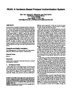
used the serial structure which can reduce the system complication, but increase the speed and quality of system with the help of the advanced data acquisition and signal processing techniques. The modular structure design is used in the system. It includes mainly the following modules: multi-frequency current source module based on direct digital synthesis (DDS), driving module, measuring module, data acquisition module, and high speed real-time controlling module. High speed digital signal processor (DSP) is used as the controller and micro-processor. A. Multi-frequency current source module based on DDS In the range of working frequency for EIT, the contact resistance between electrodes and skin is about in the range of 200-2000 Ω / cm 2 . Current driving pattern and voltage measuring pattern are used in order to overcome the influence of the contact resistance. This module produces the driving current which is sine wave with low distortion in the frequency range from 1 KHz to 2MHz. It is used to convert the voltage signal to current. The current is proportional to the output of the waveform. Multi-frequency source offers much greater flexibility in the current distribution, but is much more difficult to construct. The multi-frequency current source module based on DDS includes signal generator, low pass filter and V/I conversion, etc. The schematic diagram is shown in Fig.1. Fre q u e n c y d is p la y
A D 7008
DSP
50M H z
A2
R4
R3
A1
R5 V0
Vi
A3
K e y b o a rd
R2
c o n tro l
I0 RL
R1
A D 7008
Fig. 2. Hardware system structure block diagram
c lo c k
Lo w -p a s s filte r
keyboard control circuit, signal generator can produce an accurate sine signal, and also can realize real-time adjusting at the frequency, the phase and the amplitude. Because the highest frequency output in this system is 2MHz, the higher frequencies can be filtered out by low pass filter. Here a second-order low pass filter is designed to realize signal filtering. Voltage-controlled current source with triple-operational amplifiers is used to transfer voltage source into current source which are shown in Fig.2 which is a voltage-controlled current source (VCCS) circuit. The approach usually adopted in conventional EIT system consists in injecting one or several currents using VCCS-type current generators, and in measuring voltages. This is because system of this type is less sensitive to the errors due to the unknown electrode contact impedance, provided these impedances are low related to the generator’s output impedance and the voltmeter’s input impedance.
Vo lta g e c o mp a ra to r
V/I c o n v e rs io n
From Fig.2, the output current is calculated by the following: R4 Vi R3 + R4 (1) I0 = R1R5 R1 R4 − ( )R L + R1 + R2 R3 + R4 R1 + R2 Here, if R1 R3 − =0, R1 + R2 R3 + R4
Fig. 1. The schematic diagram of multi-frequency current source
DDS is a new frequency synthesis technique developed in recent years [4]. The AD7008 is a numerically DDS chip with crystal oscillator, 32-bit phase accumulator, sine and cosine look-up tables, and a 10-bit D/A converter, which is integrated on a single CMOS chip. The two pieces of AD7008 are controlled by DSP and used to produce triggering and demodulating signals, one generates the sine signal, the other generates impulse signal. In order to ensure the sine signal and the impulse signal synchronization, a common digital crystal oscillator of 50MHz is used in the two pieces of AD7008. With the help of
or We can get
(2)
R1 R4 = R2 R3 ,
R4 (3) Vi R3 + R5 The equation (3) shows that the output current is in proportion to the input voltage when R3, R4, and R5 are constant. The output impedance of the multi-frequency current source pattern is over 1.1MΩ . And the frequency, the phase and the amplitude can be adjusted dynamically in the frequency range from 1 kHz to 2MHz. I0 =
B. Driving and measuring module There are multiplexers, isolation circuit and control unit in this module. MAX306 as multiplexers is used to switch the driving and the measuring circuit under the controlling of DSP. Before the current flows into and out of the module, they should get through an isolation circuit which is consisted of trigger pulse transformer for the purpose of electricity isolation.
protocol to communicate serially with other controllers in electrically noisy environments. DSP TMS320F2812 is used as the controller and microprocessor in this system. It controls not only every module in real-time accurately, but also the signal frequency, the phase and the amplitude by software or peripheral circuits. The whole structure diagram and picture of this system are
C. Data acquiring module The data acquiring module is consisted of pre-amplifier, low pass filter, demodulation circuit and AD convertor circuit, the schematic diagram is shown in Fig.3. AD624 is used as pre-amplifier, which has high input impedance and adjusting gain by programming. A fourth-order Butterworth low pass filter designed with MAX275 is used to get rid of signal
Im a g in g
C o m p u te r
S e ria l c o m m u n ic a tio n In te rfa c e
D SP
DDS
A /D c o n v e n to r
C lo c k
DDS
C o m p a ra to r
Fig. 3. The schematic diagram of data acquiring module
noise. The differential amplifier measures the potential difference between a pair of electrodes. The amplitude of this signal represents the magnitude of the impedance of the body, while its components, which are in phase and in quadrature with the current generator, represent the resistance and reactance respectively. The synchronous demodulator can extract the in-phase and quadrature components of the voltage signal. The output of the demodulator is a DC potential whose amplitude represents either resistance or reactance, depending on how the demodulator is synchronized. With high speed sample and hold technology, synchronous signal triggers demodulation circuit first. Then the sine signal is demodulated into a direct voltage signal which will be sent into A/D converter triggered by sampling impulse. Lastly, the analogue signal is converted into digital signal which is sent into DSP for processing. In order to conform with the electrical safety regulations of patient connected equipment, the PC and data acquisition system are isolated from the analogue electronics via opto-isolators, which are included on the digital I/O lines and between the demodulator and the sample and hold circuitry. D. High speed and real-time controlling module DSP processor is microprocessor designed to perform digital signal processing—the mathematical manipulation of digitally represented signals. Digital signal processing is one of the core technologies in rapidly growing application areas such as wireless communication, audio and video processing, and industrial control, etc [5]. This module supports digital communication between the CPU and other asynchronous peripherals that use established
P ro g ra m m a b le
L o w p a s s filte r
a m p lifie r
D e m o d u la to r C u rre n t so u rc e F ilte r
In stru m e n ta l a m p lifie r
M u ltip le x e r s
M u ltip le x e r s
E le c tro d e s
E le c tro d e s O b je c t
Fig. 4. The structure diagram of the EIT hardware system based on DSP .
Fig. 5. The picture of the EIT hardware system.
shown in Fig4 and Fig.5 respectively. 2) III. MEASUREMENT AND IMAGING A. Physical phantom One problem in practical use of EIT is the attachment of electrodes. Two tissues must be addressed: the practical problem of attaching a large number of electrodes in a reasonable time, and producing a low-impedance contact with the tissue. So the physical phantom of EIT with 16 electrodes is used. And the electrodes are designed into hybrid structure type, in other words, slice electrode is used as current driving electrode and dot electrode is used as voltage measuring electrode. A water tank with diameter 30cm and height of 20cm was used. The tank was filled with saline (NaCl) solution. Some targets with different impedance were put into the tank. B. Experiments of imaging To evaluate the performance of the system, we carried out the measurements. The back projection algorithm is used in image reconstruction. The frequency is at the 50KHz . In Fig.6, some pieces of aluminum (better conductivity), and plexiglas (worse conductivity) are used in experiments, they are (1) one piece of aluminum and one piece of plexiglas (2) three pieces of plexiglas. In Fig.7, some experiments in vitro tissue are doing: (1) one piece of muscle and one piece of bone (2) two pieces of fat and one piece of bone. C. Discussion From Fig.6 and Fig.7, the position of different targets are clearly visible, that is, they all got more clear reconstruction conductivity distribution image. It is shown that this system and the algorithm used are feasible. But the shape of the target objects is not very clear, which due to the reconstruction algorithm. IV. CONCLUSION 1)
This EIT system has some characteristics as follows: Modular structure is used in designing system, and it makes the system with better expandability and
Fig. 7. (a) The different kinds of experiment phantom (There are some pieces of fat, muscle and bone). (b)The reconstruction images of conductivity distribution..
3)
DSP is used as the controller and microprocessor, it can not only achieve real-time image quickly and accurately, but make the system with higher stability and better anti-interference ability. V. FUTURE WORK
This system can meet the need of real-time imaging, but it is far from clinical application. So the further work should be done as follows: 1) Increasing the number of the electrodes in order to achieve much more information for improving the imaging precision. 2) Adopting static algorithm or quasi-static algorithm in order to make full use the feature of the multi-frequency system. 3) Improving the original physical model and the electrodes structure. REFERENCES [1] [2]
[3]
[4] [5]
Fig. 6. (a) The different kinds of experiment phantom (There are some pieces of aluminum, or plexiglas). (b)The reconstruction images of conductivity distribution.
portability. Driving source is designed with DDS, the frequency, the phase and the amplitude can be adjusted dynamically.
David Isaacson and Jennifer Mueller, “Biomedical Applications of Electrical Impedance Tomography,” Physiol. Meas. Vol.24, 3-5, 2003 K.Boone, D.Barber and B.Brown, “Review Imaging with Electricity: Report of the European Concerted Action on Impedance Tomography”, Journal of Medical Engineering &Technology, Vol.21, No.6, 210-232,1997 Guizhi Xu and Shuai Zhang, “The Acquisition Hardware System with Direct Digital Synthesis and Filtered Back-Projection Imaging in Electrical Impedance Tomography,” Proceedings of the 27th Annual Conference of IEEE Engineering in Medicine and Biology, Shanghai, China, September 1-4, 2005. Data Sheet, CMOS DDS Modulator AD7008, Analog Devices, Inc., 1995 Data Manual, TMS320F2812 Digital Signal Processors, Texas Instrument., Literature Number: SPRS174H April 2001–Revised March 2003.