Hardware Software Codesign of DSP System Using Grammar Based Approach A. K. Deb, A. Hemani J. Öberg
A. Postula
D. Lindqvist
Royal Institute of Technology ESD Lab, Electrum 229 164 40 Kista, Sweden
Dept. of CSEE University of Queensland St Lucia Campus Brisbane 4072, Australia
Ericsson Radio Systems AB, Farögatan 6 S - 164 40 Kista Sweden
abhijit|ahmed|
[email protected]
[email protected]
[email protected]
Abstract Embedded cores are gaining widespread use to deal with the complex DSP systems where flexibility is of utmost importance. The design of such a system offers several problems, which is not addressed by the existing methodology. The authors previously presented an integrated grammar based DSP design methodology that separates architectural and functional specification, can create a virtual prototype and has a smooth link to the implementation phase. In this paper we present the extension of the work to handle embedded cores. Here we capture the Host Peripheral Interface (HPI) of TMS320C6x core at higher level of abstraction and provide a single simulation environment, which facilitates faster analysis of hardware software components. Our results reveal that the proposed methodology offers simulation time speed-up of 5 times and design time speed-up of 8 times, while keeping the architectural specification separated from functionality.
1.
Introduction
To cope with the complexity and gain flexibility to adapt to changing requirements, specialized systems often use a specific hardware platform in conjunction with a software part. This is further aided by the fact that shrinking geometry and accompanying increase in performance in many instances allow functions to be implemented in software that earlier required implementation in hardware. Hence, embedded cores are great system design components to gain flexibility but they pose design problems that are not well addressed by existing methodology. The current practice of embedded system design starts with a written specification of the product
that is passed to the architectural design team. The team then carries out a manual partitioning into chips or chipsets, writes a primary specification for the device and hand it over to chip development team. The team then starts with RTL coding to implement the chip while the algorithmic modeling is done in C or C++ [1]. But RTL level is too detailed to be efficient enough to meet the time to market requirement. Thus HW/SW repartitioning, substituting better programmable VCs or custom hardware accelerator for part of the software become rather difficult. Therefore, if a design needs to evolve to deal with the next generation of products, we need to capture an embedded system at the highest level of abstraction. The authors have presented a grammar based DSP design methodology called MASIC, Maths to ASIC [2,3]. Here we present the extension of our work to make MASIC capable of handling embedded cores while keeping the architectural specification apart from the DSP functionality. The benefits of such an approach are: • Separation of architectural specification from DSP functionality makes it convenient to amend the design with different product family. • This methodology captures the architecture using grammar notation and dataflow using C function that facilitates the designer to explore the design with different HW/SW combination. • It allows concurrent development of architecture and dataflow that is highly desirable in industry to meet time to market requirements. • Our results show that it offers simulation time speed-ups along with reduction in design time. This paper illustrates the methodology and quantifies the results. In the next section we present related works in embedded system design.
Section 3 outlines the MASIC methodology and the following section describes the extension of the work. Section 5 shows the results and finally, we finish the paper with discussion and direction of future work.
2.
Embedded System Design
Various methodologies have been proposed to address the codesign task. The approach to automate the HW/SW systems are categorized as [4]: • Fully automated synthesis approach – it is attractive in the sense that this approach automatically derives an implementation from detailed functional specification. • Semi automated approach – leaves the design decisions, HW/SW partitioning in the hands of designer. Thus it provides an environment where the designer can organize the design to meet his requirements. In this context, the simulation speed is of particular interest, since a huge number of simulation steps must be performed either to warranty the system’s functional correctness or to evaluate the quality of a hardware-software partition [5]. This consists of moving blocks of instructions towards hardware or software respectively starting from a software or hardware implementation [6]. Instruction level simulators are key tools for processor architecture while system simulators play a vital role for the design of system that includes both hardware and software. Pétrot et. al. have categorized the three main approaches for simulation of core based embedded systems [5]: 1. Simulation of the whole system on the same host platform, where hardware components are designed using hardware specification language and software is compiled for the target processor. 2. Emulation of the hardware on a board, for example using FPGA and simulation of the software on a host processor. However, the main drawback of such an approach is the synchronization needed to communicate the specialized hardware with the host back and forth. 3. The third approach is to run both software and hardware on an emulator, i.e. execution of the program on an emulated environment. All these approaches offer their own advantages and disadvantages. Hence, the Design Automation Conference had a panel to probe the mysteries of hardware-software codesign [7]. The
panel pointed problems:
out
the
following
codesign
• Lack of tools for use early in the design process and a lot of codesign tools are actually coverification tools. • By the time coverification tools come in to play, the design team has already made a commitment to much of the architecture. Thus the designer gets poor choices in partitioning between hardware and software or selecting a hardware core. • On large multiprocessor projects, system development cost is dominated by software cost, since it often consumes more engineer days than the hardware development. • Lack of automation tools forming a single simulation environment. Some popular modeling tools are TRANSCEND, SIMSCRIPT, SLAM, ADAS. Tools like, COSMOS and CoWare address the support for HW/SW allocation, partitioning and interface design in codesign process. However this tools mainly aim at HW/SW co-specification, where partitioning is assumed to be done in the very beginning. This means the designer cannot turn back to the partitioning phase easily [8]. However, different partitioning or substituting a core with new generation of product is easier in the proposed methodology, which will be explained later.
3.
The MASIC Methodology
From an implementation perspective, DSP systems can be divided into two components: the first is responsible for bringing the right amount of data at right time to the right place and the second is concerned with performing the correct DSP computation, given that the first component is working. Performance requirements in digital system demand intricate DSP computation, which contributes to the complexity of the second component. Several factors have contributed to the increased complexity of the first component involved in movement of data: Firstly, today we can integrate tens of DSP blocks in a single device, requiring a complex global control scheme. Secondly, competition, changing standards, ability to work with different generation of products and different product families require DSP ASICs to be highly configurable. Collectively, we call this component Global Control, Configuration and Timing or GLOCCT. GLOCCT is inherently tied to the chip level architecture: processor cores, busses, memories
and external interface. In telecom industry, standards like GSM, DAMPS have a relatively much longer life than the implementation architecture. This requires that the GLOCCT, which represents the implementation architecture be kept separated from DSP computation or dataflow, which is tied to the algorithm standard. Architectural Decisions
Functional Modeling
Benefits C function • Global control and timing enters the Grammar design flow Compiler early at the behavioral level. VHDL + C • Architectural Virtual Prototype and functional specifications are active ingredients of the subsequent design phase. • Global control and data flow are kept RTL separated. Design
micro-controllers. Since the cores are fully tested, chance of a design error is thus reduced. What is left for the designer to do is to map the DSP algorithms to these cores and define the communication between the core and the host. The host architecture is defined in chip level GLOCCT using grammar notation. The chip level GLOCCT embodies instances of embedded cores and interacts with them. Interface Registers
Manual Design
IP Based
Behavioral Synthesis
Grammar notation
Figure 1: MASIC design flow and its benefits
Modeling in MASIC begins at the functional level where the algorithm development and verification is concerned with making sure that the specified signal processing figures of merit are met. However, the functional level model computes results with infinite precision. Therefore, next the system is verified using the bit true simulation environment like DSP Station, SPW or COSSAP. At this level we evaluate the quantization noise introduced by finite word length effects. The output of this phase is a set of DSP functions in C. Next the architectural decisions are captured using compact grammar notations. We have developed a grammar compiler that reads the grammar notations and generates a VHDL model that links to the C functions. Later, the ModelSim simulator is used to perform a cosimulation between VHDL and C. Figure 1 depicts the methodology and points out its benefits.
4.
Extension of the Methodology
The MASIC methodology has been extended to allow designer to make use of libraries consisting of complex component models. The library can contain wide variety of macrocells, varying from single devices such as UARTs or A/D converters to more complex ones like processors, DSPs or
Buses & signals
Interface Controller
Software written in C or Assembly code Core GLOCCT captured using grammar
Figure 2: MASIC model of the core
We view the core at two different layers as shown in Figure 2. The primary intention of the model is to focus on the interfaces between the host and the core. The outer layer provides the interface to the GLOCCT. This layer includes peripheral registers, buses and the associated control logic, which is referred to as core level GLOCCT. The inner layer contains the software in C, which is a DSP function developed in the bit true modeling phase of the design cycle. Grammar notations are used to describe the core level GLOCCT, which provides communication between the host and the software running on them. So bus functional model can be used for of the hardware, while the DSP software would run on a model of the target CPU. The DSP computations done in C are mapped to instruction set processor. The core level GLOCCT is stored in a library and can be reused with different DSP algorithm. Here, we use the TMS320C6x cores. The reason for choosing this core is quite evident. It has a dedicated Host Port Interface (HPI) that makes it a better candidate to be used as an embedded core. The GLOCCT and the core exchange data through this HPI. HPIs available in different C6x family differ to some extent. The HPI of C6201 (fixed point) / C6701 (floating point) uses the DMA auxiliary channel to access the memory while the HPI is directly tied with the internal address generation hardware in C6211/C6711.
4.1
Specifying the Core in MASIC
We start by creating the model of the core using the MASIC notation. The core GLOCCT
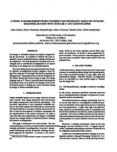
communicates with the host using the HPI. The HPI is a 16 bit parallel port through which a host processor can directly access the core’s memory space. The host device functions as a master to the interface. HOST
HPI of C6211
R/W Data[15:0] Datastrobe ALE (if used) Ready Interrupt
HHWIL HR/W HD[15:0] HDS1 HDS2 HCS HAS HRDY HINT
HPIA
HPID
Address generation Hardware
HCNTRL[1:0] Address
HPIC
Figure 3: The HPI of C6211 / C6711
Figure 3 elaborates the HPI of C6211 [9]. Three HPI registers are used to communicate between the host device and the CPU. These are HPI Data (HPID) register, HPI Address (HPIA) register and HPI Control (HPIC) register. Using the HCNTL[1:0] control inputs, the host can specify an access to either of these HPI registers. The HR/W signal determines a read or a write access. HPIA contains the address of the memory accessed by the HPI at which current access occurs. The host can access HPID with an optional post increment of the value stored in HPIA, when the HCNTL[1:0] is set for block data transfer. Thus it removes the need for the host to load incremented address into HPIA. The address strobe (HAS) is used for hosts having a multiplexed address/data bus. Because of the 32 bit word structure of the chip architecture, all transfers with a host consists of two consecutive 16 bit halfwords. The HHWIL pin indicates whether the first or the second halfword is being transferred. The HWOB bit in the HPIC register determines whether the first or the second halfword is the most significant halfword of a word. The HPI ready (HRDY) pin allows insertion of host wait states. The HRDY provides the way to adjust the host access rate; thus no software handshake is needed. We have built the FSM model of the core GLOCCT, which controls the read/write operation to/from three HPI registers. The control signals, registers and the FSM are described using the grammar notations. Figure 4 shows the MASIC notation to describe HPID write operation. We begin by declaring the types, which is used later. The MASIC compiler processes these statements and generates the corresponding code in a VHDL package.
-- Type Declaration type HalfType std_logic[16]; type WordType std_logic[32]; type MemType WordType[1024]; -- Interface Section interface C6211 ( input CNTRL std_logic[4], output RdInt std_logic[2], inout HD HalfType, clock 1MHz, reset std_logic ); -- Storage Section array RAM MemType; internal HPID, HPIC, HPIA WordType; -- Grammar Productions rule; (CNTRL) @ 1 MHz : “1100” { HPID[15..0]