Paper Code: 01A7
Multi-phase Fuzzy-based Modeling and Control of Combined Cycle Gas Turbine Plants Amgad H. Salah1, Mostafa A. Elhosseini 2, Ragab A. El Sehiemy3, Kamal M. Shebl4 1
Msc student at department of electrical engineering, Mansoura University, Egypt Ass. Prof. Computer engineering and control system Department- Mansoura University, Email:
[email protected] 3 Department of electrical engineering, Kafrelsheikh University, Email:
[email protected] 4 Department of electrical engineering, Mansoura University, Egypt
2
Abstract- Combined cycle gas turbine (CCGT) has become an important technology for power generation due to its significant effect on power system stability studies. A simplified mathematical model of CCGT has been proposed to study the dynamic response of the CCGT under normal operation condition with a small load perturbation condition. This paper is interested with the implementation of fuzzy logic control (FLC) in the control system of CCGT considering the limitations on the system inputs. The aim of the fuzzy logic controller is to maintain the system speed, exhaust temperature (Te) and air flow (Wa) within desired interval further, it is required to make the coordination between fuzzy speed control signal and exhaust temperature control signal using fuzzy fuel control system to compute the accurate value of fuel signal which provide fast reaction time. The simulation results shows the improvement of combined cycle gas turbine dynamic response with fuzzy logic control systems compared to the conventional model of CCGT under normal and abnormal conditions. Index Terms—Combined cycle gas turbine, Fuzzy Logic, Frequency drop, Dynamic response.
I.
INTRODUCTION
In Egypt [1], Because of the continuous increase of load demand and shortage of the generation, we suffer from the daily disconnection of electricity in the last few years therefore, the addition of new generation with combined cycle technologies is one of the wide spread significant trends to maintain system frequency within limits and also increase the reliability as well as the security of the power system. Combined cycle gas turbine (CCGT) has many powerful features that include a great effect on the frequency regulation of power system, high energy efficiency, low installation cost, flexibility to fluctuations in electrical load, low maintenance cost, quicker reaction time
and low emission compared to other conventional thermal units. During last decades, there has been continuous development of combined cycle gas turbine (CCGT) to improve its dynamic response. Many researchers have built mathematical models for gas turbines (GT) which are the key part of CCGT system based on Rowen's heavy gas turbine model [2, 3]. The IEEE working groups developed their model that is suitable for the dynamic performance studies [4]. In [5], the variation of combined cycle gas turbine parameters with temperature control was studied. Further, a comparative study on different models of gas turbines in CCGT has been discussed in [6]. Studies in [7] discussed the response of different types of governor-turbine system controller under frequency changes. Due to its large effect on primary frequency regulation stability of power system, many researchers have studied the change in dynamic response of CCGT in response to change in system frequency [8-10]. However, N. Kakimoto and K. baba [11] have studied the detailed analysis that has been lacked in the previous researches which explain how the plant variables behave for frequency drop. The authors in [12] studied the effects of varying CCGT parameters on the efficiency of the CCGT which has improved by increasing the maximum cycle temperature ratio. Another concept has been made in [13, 14] to improve the mathematical model of CCGT by improving the governor system of CCGT using PID controller. The simulation results indicated that the system dynamic response has improved. In [15, 16], the genetic algorithm as an optimization technique was developed to identify the parameters of the proposed model. The simulation results indicated the feasibility of the proposed model. Additionally, reference [17] allows the users to rapidly develop physical models during start-up
31
Amgad H. Salah et. Al. – International Conference on New Trends for Sustainable Energy 2016 [ICNTSE] process using Modelica. However, these models are designed for simulation, and are not immediately suitable for optimization purposes. L.Chandra and S. K. Sahu [18] have studied the performance of some classical control and found that PID controller has better performance over the other controllers with different types of optimizing techniques. Studies reveal that firefly optimized PID controller is the best over other controllers. Robust controller has been designed for power plant gas turbine in [19] to maintain the speed and exhaust temperature within limits. Simulation results show the improvement in the performance compared to PID control. In [20], it was implemented a fuzzy logic controller in the control system belonging to the governing system. The results obtained during start-up and picking load operation showed better results that improved those obtained with the PID control and robust controller. However, the authors in [20] were not interested in the dynamic response of CCGT in response to change in system frequency.
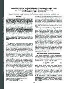
Fig .2: Sub model of combined cycle gas turbine
Fig. 1 shows the single shaft combined cycle gas turbine. In gas turbine plant, the air is drawn into the axial compressor and compressed through multiple stages of blades. High pressure air is mixed with the fuel in the combustor and the mixture is ignited to make high temperature and high pressure combustor gas. The hot gases drive gas turbine. To achieve high energy efficiency and additional electricity ,high temperature exhaust gas that are fed into the waste heat recovery boiler should be maintained at the maximum allowable level by controlling the air and fuel circuits[11]. The combination of these two thermodynamic cycles is called CCGT where the output power is the sum of the gas turbine output and steam turbine output. The mathematical equation of the thermodynamic parts of the gas turbine and steam turbine is derived depending on the adiabatic compression and expansion procedures as listed below for delivering small signal model. The chain of sub models of combined cycle gas turbine described above is shown in fig. 2, to identify the input and output variable of each sub model and the coupling between the blocks. The details of each of sub models are developed in the next section.
Simulation results in [21] have been implemented in order to obtain the required speed response under transient and steady state behaviour. The performance of the CCGT has been developed in [22] by designing a fuzzy logic controller on blade path temperature to activate the high temperature runback control. Further, a fuzzy logic controller is applied for the throttle pressure limits to compute the better value of the bypass valve demand to get the steam turbine demand. But the response time of steam turbine is large and the valve position dynamic for gas turbine is oscillatory. The present paper makes analysis for the dynamic model of CCGT and its control loops during normal and load changing condition. The proposed method uses fuzzy logic control to improve speed, temperature and air flow control signals. Additionally, making coordination between fuzzy controlled speed signal and temperature signals to compute the accurate value of fuel signal which provide a fast response time against the system disturbance. This paper is organized as follows: section 2 presents the problem formulation of the CCGT model. The modeling and description of control blocks of CCGT with and without fuzzy logic control is discussed in section 3. The computer simulation and analysis of the results will be presented and discussed in section 4.
The air flow in gas turbine (W) is compressed adiabatically so the compressor discharge temperature can be calculated as follows: (1) ,
,
(2)
,
(3)
II. PROPLEM FORMULATION
Where
: rated atmospheric pressure. : rated atmospheric temperature.
: air flow at and (assume W: air flow in per unit of its rated value. : Atmospheric pressure. : Compressor inlet temperature. : Compressor efficiency. X : the compressor temperature ratio. : Design compressor pressure ratio.
Fig. 1 Single-shaft combined cycle gas turbine
32
).
Amgad H. Salah et. Al. – International Conference on New Trends for Sustainable Energy 2016 [ICNTSE] : Ratio of specific heat. Gas turbine inlet temperature combustor heat balance: , Where
(k) is calculated from the
(4)
: fuel flow in per unit of its rated value
: rated gas turbine inlet temperature. : rated compressor discharge temperature. The fuel flow is a negligible amount compared to the airflow. Gas turbine exhaust temperature (k) is described as follows: , (5) Where
: turbine efficiency.
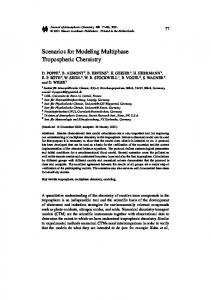
The exhaust gas flow is practically equal to the airflow. Moreover, the net energy provided to the gas turbine can be calculated as follows: Fig. 3: Simulink model combined cycle gas turbine
(6) where
: gas turbine output coefficient.
Steam turbine and heat recovery boiler depend on the exhaust gases out from gas turbine which collect some energy that can be calculated as follows: (7) ,
where
: steam turbine output coefficient.
III. CONVENTIONAL MODEL OF CCGT In this study, 1100 class single shaft combined cycle gas turbine is considered. Its rated power output is 160MW. The typical parameters of the gas turbine and the steam turbine are provided in [11]. The model is implemented on MATLAB/ SIMULINK version 7.12. Fig. 3 shows the dynamic model of combined cycle gas turbine. The model consists of several blocks that describe the control circuits such as speed/load control, temperature control , fuel control and air control further, other blocks are used for implementing gas turbine, wasted heat recovery boiler/steam turbine, rotor shaft and temperature transducer. These blocks should be studied in order to optimize the performance of combined cycle power plant.
The speed/load block (governor) is activated when there is any speed deviation from the nominal value. The speed/load control sends a control signal to participate with exhaust temperature control signal to low value selector which determines the required fuel signal control. The temperature control block contributes with speed/load control signal in determining fuel control signal that enters the fuel system. The measured exhaust temperature is compared with the reference exhaust temperature and the corresponding error affects the temperature control. To keep thermodynamic limits of the unit, the measured exhaust temperature must not exceed the reference temperature. Air flow control block adjusts the required air flow through control the inlet guide vans position to keep the exhaust temperature under limits and Preserve thermodynamic limits of the unit. Therefore the exhaust temperature is kept blow a reference temperature by an appropriate value Fuel control system depends on the two signals that exit from the speed/load block and the temperature control block. The low value selector compares between them and the lower value is selected and used in determining the required amount of fuel flow.
IV. PROPOSED MODEL OF CCGT WITH FUZZY LOGIC CONTROL Fuzzy logic control is introduced by L. Zadeh and Mamdani [23] based on human experts and process knowledge to create a control rules. The proposed method uses the fuzzy logic control instead of conventional methods because it is easy to design, easy to implement and more robust than other conventional controllers. The main components of a fuzzy logic controller can be summarized as follows:
33
Amgad H. Salah et. Al. – International Conference on New Trends for Sustainable Energy 2016 [ICNTSE]
table which describes the linguistic rules adopted. The corresponding five linguistic terms for each input involves 25 linguistic rules as shown in table I. In the first raw, the speed control signal (output) increases with the increasing of
Rule Base — contains expert's knowledge, as a set of rules, and process knowledge to control the system. Fuzzification interface — it converts the fuzzy inputs in order to interact with the rule based. Inference mechanism — selects the control rules that are effective and decide the control signal that must be generated. Defuzzification interface — it converts the fuzzy control signal to un-fuzzy process control signal.
error deviation ( ) at constant value of the error (e) which indicates that the error deviation has an effect on the value of the speed control signal (output). TABLE I LINGUISTIC VALUES OF THE MEMBERSHIP FUNCTION OF THE SPEED CONTROL INPUT AND OUTPUT
NB NB NB NB NM ZE
e/ NB NM ZE PM PB
Fig. 4 shows the proposed fuzzy control system of the CCGT. The proposed controllers aim to control CCGT speed and exhaust gas temperature additionally, an appropriate coordination between fuzzy controlled speed signal and fuzzy controlled temperature signal can be provided to compute the accurate value of fuel signal. Therefore, a fast response time against the system disturbance can be obtained. Comparison between dynamic performance of classic control of CCGT and proposed method during normal and abnormal condition is conducted.
NM NB NB NM ZE PM
ZE NB NM ZE PM PB
PM NM ZE PM PB PB
PB ZE PM PB PB PB
This table includes the 25 linguistic rules of the membership functions where: NB: Negative big. NM: Negative medium. ZE: Zero error. PM: Positive medium. PB: Positive big.
a.
b.
Fig. 4: MATLAB simulation of fuzzy controlled CCGT model
Membership function of speed error input
Membership function of speed error deviation input
A. Fuzzy speed/ load control: As shown in fig. 4, the new fuzzy speed /load control system can be used instead of classic speed governor which has two inputs and one output. The inputs to the fuzzy speed /load control are the speed/load error (e), the speed/load error deviation ( ) and the output is the speed control signal
c.
that participates the temperature control signal
to determine an accurate required amount of fuel. The inputs have five membership specific functions of triangular type as well as the output as shown in fig.5. The ranges of each membership are selected by trial and error using numerous experiments to get the best ranges of each membership. The inference operation is made by inference table or decision
Membership of speed control signal output
Fig. 5: fuzzy speed /load control system membership functions
B. Fuzzy Temperature Control System: To improve the dynamic response of CCGT, a proposed fuzzy temperature control system is used instead of overheating control system as shown in fig. 4.The inputs to
34
Amgad H. Salah et. Al. – International Conference on New Trends for Sustainable Energy 2016 [ICNTSE] Fuzzy air flow control system is proposed to improve the dynamic response of the air flow system as shown fig. 4. The inputs to the fuzzy air flow control are the temperature error (e) between the measured exhaust temperature and the reference exhaust temperature and temperature error deviation ( ) and the output is the air control signal that adjusts inlet guide vans (IGV) and limits the required amount of air flow at different operation modes. The inputs have five membership specific functions of triangular type as well as the output as shown in fig. 7. Trial and error tuning process is used to compute the membership function ranges through numerous experiments to get the best ranges of each membership. The inference operation is made by inference table or decision table which described the linguistic rules adopted. Table III shows the corresponding two inputs with five linguistic terms and 25 linguistic rules.
the fuzzy temperature control which are the temperature error (e) between the measured exhaust temperature and the reference exhaust temperature and temperature error deviation ( ). The output is the temperature control signal that contributes the speed/load control signal to determine an accurate required amount of fuel. The inputs have five membership specific functions of triangular type as well as the output as shown in fig. 6. Trial and error mechanism is used to divide each input space into the best overlapping ranges of each membership. The inference operation is made by inference table or decision table which described the linguistic rules adopted. The corresponding five linguistic terms with 25 linguistic rules are shown in table II.
TABLE III LINGUISTIC VALUES OF THE MEMBERSHIP FUNCTION OF AIR FLOW CONTROL INPUT AND OUTPUT
TABLE II LINGUISTIC VALUES OF THE MEMBERSHIP FUNCTION OF THE TEMPERATURE CONTROL INPUT AND OUTPUT
NB NB NB NB NM ZE
e/ NB NM ZE PM PB
NM NB NB NM ZE PM
ZE NB NM ZE PM PB
PM NM ZE PM PB PB
NB NB NB NB NM ZE
e/ NB NM ZE PM PB
PB ZE PM PB PB PB
a.
a.
ZE NB NM ZE PM PB
PM NM ZE PM PB PB
PB ZE PM PB PB PB
Membership function of temperature error input
Membership function of temperature error input
b.
b.
NM NB NB NM ZE PM
Membership function of temperature error rate input
Membership function of temperature error deviation input
a.
Membership function of air flow signal output
Fig. 7: fuzzy air flow control system membership functions D. Fuzzy fuel control system: The new fuzzy control system is used to optimize the signal that enters to the fuel system as shown in fig.4. It has two inputs, speed control signal and
c. Membership function of temperature control signal output
Fig. 6: fuzzy temperature control system membership functions.
temperature control signal and the output is the control signal that enters to the fuel system. The inputs have five membership specific functions of triangular
C. Fuzzy air flow control system:
35
Amgad H. Salah et. Al. – International Conference on New Trends for Sustainable Energy 2016 [ICNTSE] of the speed signal of conventional model. The time needed from the proposed model to reach the stability is 80 sec while the conventional model needs more time to reach the stability. In Fig. 9.b the fuzzy controlled exhaust temperature ( ) reaches maximum exhaust gas of 0.85 p.u. However, the conventional model control needs more time to have maximum exhaust temperature of 0.78p.u. The response time of CCGT with fuzzy system is improved with a percentage 20% than uncontrolled fuzzy system.
type as well as the output as shown in fig. 8. The linguistic variables of the fuzzy fuel control are shown in table IV. TABLE IV LINGUISTIC VALUES OF THE MEMBERSHIP FUNCTION OF THE FUEL CONTROL INPUT AND OUTPUT
/ NB NM ZE PM PB
NB NB NB NB NB NB
a.
NM NB NM NM NM NM
ZE NB NM ZE ZE ZE
PM NB NM ZE PM PM
PB NB NM ZE PM PB
Fig. 9.c shows that the response of mechanical power with fuzzy controlled system is better than the response of mechanical power of conventional model. In this case, the time needed by the proposed model to reach the stability is 80sec. However, the conventional model needs more than 150sec to reach the stability. Fig. 9.d shows that the air flow with fuzzy control system is improved compared to the air flow of the conventional model with a percentage 25%. The amount of air flow required by the fuzzy controller under normal operation is 0.75 while the amount of air flow required by classical control is 1 p.u.
Membership function of temperature control signal input
b.
Membership of speed control signal input
a. Speed (N) of CCGT
C.
Membership of fuel control signal input
Fig.8: fuzzy fuel control system membership functions V. Simulation Results and Discussions The CCGT model based on Rowen model [2, 3] is implemented using SIMULINK to make system analysis. Computer simulation has been done to study the dynamic response of the CCGT with and without fuzzy logic control systems under normal operation and different operating conditions. At different operating conditions, load demand has been changed from 0.85 p.u to 1 p.u after 300 s.
b. Exhaust temperature (Te)
A. Response under normal operation: The simulation results at normal operation ( are represented in Figure 9. Fig. 9.a indicates the responses of speed signal of CCGT with fuzzy control and compared to those obtained with conventional model. As can be depicted, the response of speed signal is much better than the response
36
of CCGT
Amgad H. Salah et. Al. – International Conference on New Trends for Sustainable Energy 2016 [ICNTSE]
c. Mechanical power (Pm) of CCGT a. Speed (N) of CCGT
d. Air flow (Wa) of CCGT
b.
Fig. 9: dynamic response of fuzzy model and conventional model of CCGT under normal operation
Exhaust temperature (Te)
of CCGT
B. Response under load perturbation condition: The simulation results indicate that the model is improved by using fuzzy logic control than the conventional model under load changing. The load demand has been changed from .85 to 1 p.u. Figure10 shows the dynamic response with load variation. Fig. 10.a indicates that the response of fuzzy speed signal that returns to normal state in smaller time than speed signal of the conventional model during abnormal condition. The speed signal of the proposed model needs 8 sec to return to normal state while speed signal of the conventional model requires 25 sec. The response of exhaust temperature is improved by using fuzzy logic control which the time required from fuzzy exhaust temperature control to meet the disturbance is 20 sec while the exhaust temperature signal of the conventional model needed at least 40 sec to reach the stability zone as shown in Fig. 10.b. The mechanical power variations (Pm) with and without fuzzy control have been implemented as shown in Fig. 10.c. The response of mechanical power with fuzzy is improved than the conventional model which in the fuzzy controlled model, the time taken from mechanical power(Pm) to meet the load change to reach the stability is 15 sec while the response time from the mechanical power (P m) in the conventional model is 30 sec .
c.
Mechanical power (Pm)
VI. CONCLUSION In this paper, a simplified mathematical model of combined cycle gas turbine and its control loops have been examined in order to study the dynamic performance of the CCGT and its frequency regulation. However, fuzzy logic control is applied on speed control circuit, temperature control circuit, and air flow and fuel control circuit to improve the dynamic response of the CCGT under normal and abnormal operation conditions. The simulation results with and without fuzzy logic control have been obtained and compared. It was indicated that the developed model with fuzzy logic controller improves the dynamic performance of the CCGT with fast transient recovery time.
37
Amgad H. Salah et. Al. – International Conference on New Trends for Sustainable Energy 2016 [ICNTSE] [23] D.K. Chaturvedimodeling and simulation of systems using matlab and Simulink. Pp.528-603.
REFERENCES [1] [2]
[3]
[4]
[5]
[6]
[7]
[8]
[9]
[10]
[11]
[12]
[13]
[14]
[15]
[16]
[17] [18]
[19]
[20]
[21]
[22]
Ministry of Electricity and energy of Egypt, official internet site, available at (www.moee.gov.eg). ROWEN, William I. Simplified mathematical representations of heavy-duty gas turbines. Journal of Engineering for Gas Turbines and Power, 1983, 105.4: 865-869. ROWEN, W. I. Simplified mathematical representations of single shaft gas turbines in mechanical drive service. Turbo machinery International, 1992, 33.5. DE MELLO, F. P., et al. Dynamics models for combines cycle plants in power system studies. IEEE transactions on power systems, 1994, 9.3: 1698-1708 NING, C. N.; LU, C. N. Effects of temperature control on combined cycle unit output response. In: TENCON 2006. 2006 IEEE Region 10 Conference. IEEE, 2006. p. 1-4. SHALAN, H. E. M. A.; HASSAN, MA Moustafa; BAHGAT, A. B. G. Comparative study on modeling of gas turbines in combined cycle power plants. In: Proceedings of the 14th International Middle East Power Systems Conference (MEPCON’10), Cairo University, Egypt. 2010. pp. 970-976, Dec.2010. HANNETT, L. N.; KHAN, Afzal. Combustion turbine dynamic model validation from tests. Power Systems, IEEE Transactions on, 1993, 8.1: 152-158. MAZHABJAFARI, M.; JAFARI, Ali M.; SAIDABADI, K. Notice of Retraction Modeling and simulation of combined cycle power plants participating in network frequency control. In: Power Engineering and Automation Conference (PEAM), 2011 IEEE. IEEE, 2011. p. 112-115 KUNITOMI, K., et al. Modeling frequency dependency of gas turbine output. In: Power Engineering Society Winter Meeting, 2001. IEEE. IEEE, 2001. p. 678-683. SASAKI, Tetsuo; ENOMOTO, Kazuhiro. Dynamic analysis of generation control performance standards. Power Systems, IEEE Transactions on, 2002, 17.3: 806-811. KAKIMOTO, Naoto; BABA, Kazuhiro. Performance of gas turbinebased plants during frequency drops. Power Systems, IEEE Transactions on, 2003, 18.3: 1110-1115. HASAN, N.; RAI, J. N.; ARORA, B. B. Optimization of CCGT power plant and performance analysis using MATLAB/Simulink with actual operational data. Springer Plus, 2013, 3: 275. ILIESCU, Sergiu St, et al. Gas Turbine Modeling for LoadFrequency Control. Scientific Bulletin, University POLITEHNICA Bucharest, Series C: Electrical Engineering, 2008, 70.4. ZHANG, Q.; SO, P. L. Dynamic modeling of a combined cycle plant for power system stability studies. In: Power Engineering Society Winter Meeting, 2000. IEEE. IEEE, 2000. p. 1538-1543. GAO, Lin; XIA, Junrong; DAI, Yiping. Modeling of combined cycle power plant based on a genetic algorithm parameter identification method. In: Natural Computation (ICNC), 2010 Sixth International Conference on. IEEE, 2010. p. 3369-3373. WEIMIN, Kan, et al. Study on the mathematical model and primary frequency regulation characteristics of combined cycle plants. In: Mechanic Automation and Control Engineering (MACE), 2011 Second International Conference on. IEEE, 2011. p. 2632-2635. TICĂ, Adrian, et al. Design of a combined cycle power plant model for optimization. Applied Energy, 2012, 98: 256-265. SAIKIA, Lalit Chandra; SAHU, Shashi Kant. Automatic generation control of a combined cycle gas turbine plant with classical controllers using firefly algorithm. International Journal of Electrical Power & Energy Systems, 2013, 53: 27-33. NAJIMI, Ibrahim; RAMEZANI, Mohammad Hussein. Robust control of speed and temperature in a power plant gas turbine. ISA transactions, 2012, 51.2: 304-308. SÁNCHEZ-PARRA, Marino; DE-LARA-JAYME, Salvador; BAHAMACA-FERNÁNDEZ, Luis J. A fuzzy-logic rule based speed and load controller for combustion turbines in power generation. In: American Control Conference, 2002. Proceedings of the 2002. IEEE, 2002. p. 2659-2664. M. ABOELEELA, A. FETOH, A. B. GAMAL. Fuzzy Speed Controllers of Combined Cycle Power Plants. International Journal of Innovations in Electrical Power Systems, 2011, 3.2: 109-121. SANCHEZ-PARRA, Marino, et al. Intelligent coordinated control for combined cycle power plants. In: Control Applications (CCA), 2012 IEEE International Conference on. IEEE, 2012. p. 148-153.
38