motor drives and output of their research shows that output. Torque of these motors is superior to that of normal three phase. Induction motor. Limitations on the ...
2011 IEEE International Electric Machines & Drives Conference (IEMDC)
Design and Control of Multiphase Induction Motor Archana Nanoty, Student Member, IEEE, A.R. Chudasama Abstract- Many researchers have studied multiphase Induction
motor drives and output of their research shows that output Torque of these motors is superior to that of normal three phase Induction motor. Limitations on the power level of semiconductor devices establish a barrier to the increase of converter ratings. In order to get rid of this limitation, multilevel converters have been developed where switches of reduced rating are used to construct high power level converters. Instead of multilevel converters, multi-phase machines are used: By dividing the handled power between multiple phases, generally more than three, high power levels can be achieved even using limited rated power electronic converters. The aim of this research is to implement novel design and development of six phase induction motor. Also control of the same motor is carried out when fed by two, three phase inverters. Index Terms: Six phase Induction motor, Design, Speed control, Frequency control.
I. INTRODUCTION Basically, the six-phase induction machine was introduced with two objectives. First, the opportunity to divide the output power into two three-phase groups allows the increase in the drive system power ratings. Secondly, for use with six step inverters, the pulsating torque in a six-phase machine is lower than in a three phase machine, another reason for using six-phase systems is reliability. When a failure happens in one of the phases, in the machine or in the power converter, the system can still operate at a lower power rating since each three-phase group can be made independent from each other. II. Design of Six phase IM
Where
K = 0, 2, 4
For Asymmetrical ac winding:
K = 1, 3, 5
In our case, number of poles = 4, so S = (6/2).4.[2+1] = 36 The six-phase machine uses the same magnetic frame with the baseline machine. We have the 4-pole machine with 36 stator slots. In order to keep the leakage distribution balanced, the phases are displaced among the two stator layers. The sixphases are constructed such that one three-phase group is displaced from the other one by 30 electrical degrees. Thus we have an asymmetrical six phase machine where; θm = 2. θe / p
(2)
θm = 2 . 30° / 4 = 15° mechanical
(3)
Slot pitch = 360° / 36 = 10° mechanical
(4)
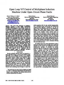
Hence, the 30 electrical degrees displacement corresponds to 15°/10° = 1.5 slots. We cannot implement such a configuration and have to use an approximation. This is done as shown below: One of the three-phase groups has the same structure of the baseline machine with half of the circuits and winding distributed in 3 slots per pole per phase (qA = 3). The second group is distributed into 4 slots per pole per phase (qX = 4) but keeping the same number of conductors per pole per phase.fig. 1 shows the actual winding. TABLE 1: MOTOR SPECIFICATIONS
When number of phase is increased, i.e. when number of phase is six, there are two, three phase windings. The two, three phase windings are displaced by 60 degrees in symmetrical design, but there is a problem of magnetic circulating currents.So asymmetrical design is implemented in which two three phase windings are displaced by 30 degrees, which eliminates 6n+-1 order harmonics [4]. Induction motor design starts from stator design. Stator design depends upon number stator slots. General expression for number of stator slots is given by, S= n/2.p.[2+K] Slots
For symmetrical ac winding:
(1)
S = no. of slots
n = no. of machine phases p = no. of machine poles And K = 0, 1, 2, 3…
978-1-4577-0061-3/11/$26.00 ©2011 IEEE
354
Frame CTF Stator Bore or Inner Diameter 125 mm Stator Slots 36 Rotor Slots 28 Conductor size 22 SWG Conductors per slot 104 No. of Turns per phase 312 Insulation Class F
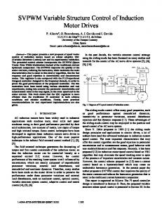
supplied from two PC based separate inverters synchronized properly with specially designed D2 card for phase shift. One inverter acts as a Master and other as a slave or follower. Standard software “NXP00002V178.VCN” was downloaded for two similar rating NXP drives. The mathematical model of six phase Induction motor is fed into VACON software. Also all the parameters of six phase 3 Hp motor were fed into the software. The VACON processor carries out motor speed control in two modes namely, viz. Frequency control and Speed control.
Fig.1 Actual Photograph at the time of winding
III.
CONTROL OF SIX PHASE INDUCTION MOTOR
Speed of Induction motor can be controlled by: 1.
Change the number of poles (in discrete increments -
Fig.2 Actual photograph of control of six phase IM
V.
RESULTS AND DISCUSSION
inefficient & rarely done) 2.
Change the frequency of the AC signal
3.
Change the slip
Changing number of poles has limitation of speed variation and it is inconvenient. Changing frequency of supply is again possible in two ways viz. Scalar control and Vector control. Six phase Induction motor can be considered as two three phase motors sharing same magnetic circuit and same shaft, speed control of six phase induction motor can be done in the same way . III.A. Vector Control
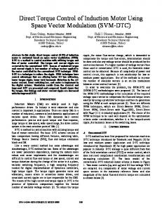
Fig.3 Current waveform for three phase, 3 HP IM
Variable frequency control consists of two types namely: Scalar control and vector control. Scalar control, as the name indicates, controls only magnitude of controllable parameter so it is obsolete. Also vector control makes ac motor suitable for applications where dc motors were used, e.g. traction [3] To carry out vector control, a d-q axis model of three phase induction motor is used because induction motor is run like a separately excited dc shunt motor. For six phase motor we need to convert two, three phase sets into two phase, i.e. ABC to dq and XYZ to d1q1. IV.
ACTUAL IMPLEMENTATION
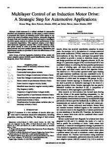
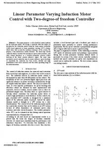
The laboratory test set up shown in fig. 2, consists of a 3 hp, 50 Fig.4 Current waveform for six phase, 3 HP IM Hz four pole 36 stator slots six phase induction machine 355
VII.
APPENDIX
Six phase IM equations: Stator and rotor voltage equations:
Fig.5 Speed-Torque curve of six phase, 3 HP IM for Scalar control
Expressions for Rotor and stator flux linkages:
Fig.6 Speed-Torque curve of six phase, 3 HP for Vector control
Figures 3 and 4 shows current waveform of three phase and six phase induction motor respectively. It is clear from waveform that six phase current is almost double that of equivalent three phase motor. Figure 5 gives a torque-speed curve for Scalar control mode of the drive while figure 6 gives a torque-speed curve for vector control. It is obvious that vector control is more precise and it gives smooth and fine speed control as compared to scalar control. VI.
CONCLUSIONS
Electromagnetic torque:
Mechanicalmodel:
Advantages of the scheme are: Applicable to six phase machine with any arbitrary angle of displacement between the two three phase winding sets whereas all vector control schemes have been developed for 30 degrees displacement. The same design can be extended for any multiples of 3, like 9 phases, 12 phases etc. The d-q axis model of six phase IM is used. By varying the phase shift between two, three phase sets, magnetic field is varied and hence speeds and torque. Thus there is no criterion of 30 deg. Phase shift, it is frequency control (Scalar) and speed control (Vector) as well as arbitrary phase displacement. No need of six phase inverter, with existing three phase inverters we can control six phase induction motor , also reliability of the system is maintained .Only we need to insert synchronization card D2.
356
Currents in terms of flux linkages:
357
REFERENCES
[3]
Modern Power Electronics and Ac Drives By B.K.Bose, Prentice Hall Publication
[1]
[4]
K. Gopalkumar, Mahopatra, “A novel scheme for six phase induction motor with open end windings.” IEEE 2002.
[5]
Electrical Machine Design- A.K.Sawhney
[2]
]Emil Levi, “Recent Developments in High Performance Variable-Speed Multiphase Induction Motor Drives” sixth international symposium nikola tesla October 18 – 20, 2006, Belgrade, SASA, Serbia. L. Romeral,Departament d’Enginyeria Electrònica. Universitat Politécnica de Catalunya “Motion Control for Electric Drives”
358