Multilevel Multiphase Feed-forward Space Vector Modulation Technique J. I. Leon, Member, IEEE, O. Lopez, Member, L. G. Franquelo, Fellow Member, IEEE, J. Doval-Gandoy, Member, IEEE, S. Vazquez, Member, IEEE, J. Alvarez and F. D. Freijedo, Member, IEEE
Abstract—Multiphase converters are being applied to an increasing number of industrial applications in recent years. On the other hand, multilevel converters have become a mature technology mainly in medium and high power applications. One of the problems of multilevel converters is the dc voltage unbalance of the dc bus. Depending on the loading conditions and the number of levels of the converter, oscillations appear in the dc voltages of the DC-Link. This paper presents a feedforward modulation technique for multilevel multiphase converters that reduces the distortion under balanced or unbalanced dc conditions. The proposed modulation method can be applied to any multilevel converter topology with any number of levels and phases. Experimental results are shown in order to validate the proposed feed-forward modulation technique.
I. I NTRODUCTION
M
ULTIPHASE variable-speed drives field has experienced a substantial growth since the beginning of this century. There has been a rapid development in some specific application areas such as: electric ship propulsion, locomotive traction, industrial high-power applications, electric and hybrid-electric vehicles, electric aircrafts, etc... [1]–[5]. Recent developments in the field of multiphase variable speed drives have led to a corresponding development of pulsewidth modulation (PWM) schemes for multiphase inverters used in these drives. Most of the existing research related to PWM control of multiphase inverters applies to two-level inverters [6]–[9]. However, the use of multilevel inverters for multiphase variable speed drives has been established as a good solution in high power applications such as electric ship propulsion and locomotive traction [10]–[13]. Multilevel topologies considered in the literature are typically either diode-clamped, flying capacitor or cascaded H-bridge converters [14]–[17]. Several space vector modulation techniques have been presented recently applied to multiphase converters of twolevel voltage source type [18]–[20]. In [21], a general space vector modulation algorithm that can be applied to multilevel multiphase converters with any number of phases and levels was presented. This algorithm, called multilevel multiphase space vector modulation (MSVM) in this paper, is based on a Manuscript received June 17, 2009. Accepted for publication September 26, c 2009 IEEE. Personal use of this material is permitted. 2009. Copyright ° However, permission to use this material for any other purposes must be obtained from the IEEE by sending a request to
[email protected]. J. I. Leon, L. G. Franquelo and S. Vazquez are with the Electronic Engineering Department, University of Seville (Spain), (e-mail:
[email protected]). O. Lopez, J. Doval-Gandoy, J. Alvarez and F. D. Freijedo are with the Electronic Engineering Department, University of Vigo (Spain).
reduction of the multilevel multiphase modulation problem to a two-level multiphase modulation problem using a two-level multiphase modulator. This two-level modulator is fed with the fractional part of the reference voltage vector to obtain a matrix, which includes a displaced switching vector sequence, and the switching times. The final switching sequence is calculated adding the integer part of the reference to the vectors of that sequence. This paper introduces a new feed-forward space vector modulation technique for multilevel multiphase power converters called multilevel multiphase feed-forward space vector modulation (MFFSVM). This modulation algorithm is a feedforward version of the MSVM technique. In this way, the notation introduced in [21] has been used to explain the proposed MFFSVM strategy. This paper is organized as follows: In section II the aim of the MFFSVM technique is presented. The mathematical description of the MFFSVM strategy is introduced in section III. An example to show the good performance of the proposed idea is shown in section IV. Finally, experimental results and conclusions of the work are presented in section V and section VI respectively. II. A IM OF THE P ROPOSED M ODULATION S TRATEGY In the most common multilevel converter topologies such as flying capacitor, diode-clamped, cascaded full-bridge or hybrid converters, the possible output voltages of each phase are equally distributed being an integer multiple of a fixed voltage step [14], [15]. However, in asymmetrical multilevel converters, this voltage condition is not true because unequal voltage steps are present in the power converter operation [22]–[24]. In both cases, symmetrical or asymmetrical multilevel converters, the control of the dc voltage balance can not be accurately achieved in all loading conditions. Load imbalances and nonlinear or transient loads have a significant impact on the multilevel converter dc voltages ripple (oscillations or actual values) [25]–[28]. As a consequence, transient imbalances and steady state oscillations can be present in the power converter operation. These phenomena lead to distorted output waveforms because the modulators usually do not take into account the actual dc voltage unbalance. Recently a work has been introduced in order to eliminate this distortion in three-level diode-clamped converters [29]. The previous MSVM technique can be applied to multilevel converters where the output voltage step between all the consecutive voltage levels is constant. However, under unbalanced
dc voltages this voltage step is not constant in general. In this case, the MSVM technique generates errors in the modulated waveforms leading to undesired distortion. The modulation technique proposed in this work solves this problem using the feed-forward concept. Some modulation strategies present in the literature use the feed-forward concept in order to achieve modulated output waveforms with low distortion for multilevel converters [30]–[33]. The feed-forward basic idea is to measure the actual dc voltages of the multilevel converter and generate the switching of the power converter taking them into account. In this way, the averaged value of the modulated output waveforms coincides with the desired reference. The proposed feed-forward space vector modulation strategy, called in this paper MFFSVM, is a simple method that can be applied to multilevel multiphase converters.
III. E NHANCED F EED - FORWARD M ULTILEVEL M ULTIPHASE SVM T ECHNIQUE (MFFSVM)
k=1
(1)
k=1
The reference vector Vr is composed of the voltage reference for each phase of the system. Switching times vector T is composed of the switching times of the switching sequence.
Vr = [Vr1 , Vr2 , · · · , VrP ]T ∈ RP 1 2 P T Vsk = [Vsk , Vsk , · · · , Vsk ] ∈ RP
T = [T1 , T2 , · · · , TP +1 ] ∈ RP +1
Mv =
S11 S12 .. .
S21 S22 .. .
S1P
S2P
1 Vs1 2 Vs1
.. .
1 Vs2 2 Vs2 .. .
P Vs1
P Vs2
1 . . . SN 2 . . . SN .. .. . . P . . . SN
(2)
Each phase j of the power converter can achieve in general N different output voltage levels and each one of these j voltages is described as Vsk (possible output voltage number j k of phase j). Each possible output phase voltage Vsk is achieved by a specific and known switching configuration of the phase j of the power converter denoted Skj . The possible switching configurations of the power converter Skj and the j corresponding phase voltages Vsk are used to define matrices S and Mv respectively. These matrices depend on the multilevel converter topology. This is the only step of the MFFSVM technique that depends on the topology of the power converter.
1 . . . VsN 2 . . . VsN .. .. . . P . . . VsN
(3)
(4)
The next step of the proposed MFFSVM technique is to generate matrix Mo which contains the elements of matrix Mv but ordered in increasing order. Matrix So (with elements j called Sok ) is obtained from matrix S ordering their elements in the order obtained in matrix Mo . In this way, each element j j Vok is still related to switching configuration Sok .
So =
1 So1 2 So1 .. .
1 So2 2 So2 .. .
P P So2 So1 1 1 Vo1 Vo2 2 2 Vo1 Vo2 Mo = . .. .. . P P Vo2 Vo1
1 . . . SoN 2 . . . SoN .. .. . . P . . . SoN 1 . . . VoN 2 . . . VoN .. .. . .
P . . . VoN
j j where Vok ≤ Vok+1
P +1 1 X Vr = Vsk Tk Tsw
Tk = Tsw
S=
In a space-vector modulation (SVM) technique, the reference vector Vr is generated by means of a sequence of space states or switching vectors {Vs1 ,Vs2 ,. . . ,Vs(P +1) }. P is the number of phases of the multilevel multiphase converter. To achieve a proper synthesis of the reference vector over a switching period Tsw , each switching vector Vsk must be applied during an interval Tk .
P +1 X
(5)
In order to consider any dc voltage in the multilevel power converter, voltage vectors Vr and Vsk and switching times vector T are normalized determining respectively vectors vr and vsk and t. It is important to remark that all vr and vsk and t belong to the multidimensional space of real numbers RP ≥ 0. The normalization of the voltage vectors is done using the lowest output voltage of each phase and the difference between the highest and the lowest output voltages of each phase. On the other hand, the switching times vector is normalized using the switching period Tsw . These calculations force that the values of all the normalized voltage vector components are in the range [0,1]. vr = [υr1 , υr2 , . . . , υrP ]T 1 2 P T vsk = [υsk , υsk , . . . , υsj ]
t = [t1 , t2 , . . . , tP +1 ]
υrj = j υsk =
j Vrj − Vo1 j j VoN − Vo1 j Vsk − Vo1 j j VoN − Vo1 Tk tk = Tsw
(6)
∈R ∈R (7)
j Each element Vok of the output voltages matrix Mo is also normalized obtaining the normalized positive matrix of possible output voltages of the power converter mo .
mo =
1 υo1 2 υo1 .. .
1 υo2 2 υo2 .. .
... ... .. .
1 υoN 2 υoN .. .
P υo1
P υo2
...
P υoN
j where υok =
j j Vok − Vo1 j j VoN − Vo1
j j = υcm+1 υn+1
The final step of the proposed MFFSVM technique uses the two-level multiphase SVM algorithm presented in [21]. In order to use it, vector vf has to be normalized using j the difference between the υnj and υn+1 . In this way, the normalized reminder of the voltage vector vf ∆ is calculated as
∈R
(8)
Each component of the normalized reference vector vr is compared with the corresponding output voltages of its phase obtaining matrix mc . mc =
1 υc1 2 υc1 .. .
1 υc2 2 υc2 .. .
P υc1
P υc2
1 . . . υck 2 . . . υck .. .. . . P . . . υck
−1 j υok
j if υok > υrj otherwise
½ j where υck =
vn = vf =
(9)
∈ RP ∈ RP
(10)
Elements of vector vn can be easily determined. Components υnj are real numbers and are equal to some element of the row j of matrix mo . Therefore, υnj are normalized values of one output voltage of phase j of the power converter present in matrix Mo which can be directly achieved by a specific j switching state Sok of phase j in matrix So . Therefore, vector vn can be achieved using a switching vector of the power converter. j j j j υnj = max[υc1 , υc2 , · · · , υcN ] = υcm
(11)
The rest of the voltage vector vf is determined as the difference between vr and vn as was introduced in section III. υfj = υrj − υnj
(13)
vf ∆ = [υf1 ∆ , υf2 ∆ , · · · , υfP∆ ]T ∈ RP υfj ∆ =
υfj
(14)
j υn+1 − υnj
Vector vf ∆ can be used directly as the input of two-level multiphase SVM algorithm introduced in [21]. The result of this method are matrix D and vector v ˆf ∆ (which is vf ∆ vector sorted by descending values) and the switching times vector t of the switching sequence with elements tk equal to
The normalized reference vector vr is decomposed into the sum of its nearest possible normalized positive voltage level towards to zero achieved by the power converter vn and the rest vf . vr = vn + vf 1 [υn , υn2 , · · · , υnP ]T [υf1 , υf2 , · · · , υfP ]T
matrix mc . This second switching vector vn+1 is achieved by j the switching state Som+1 of phase j in matrix So .
(12)
Vector vf also belongs to the space RP but it cannot be directly synthesized by means of a single switching vector. It has to be approximated with a sequence of two switching vectors. The first switching vector is vn and the second switching vector is defined as vector vn+1 that can be obtained from
1 1 − υˆf ∆ , k−1 υˆ − υˆfk∆ , tk = fP∆ υˆf ∆ ,
if k = 1 if 2 ≤ k ≤ P if k = P + 1
(15)
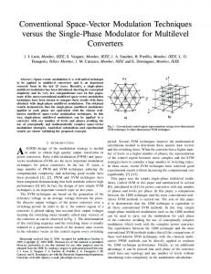
Matrix D result of the two-level multiphase SVM algorithm shows the order of the switching between the different phases of the converter. Ignoring first row and column of matrix D, reading the columns from left to right, only one element of each column changes from 0 to 1 compared with the previous one. The row’s element shows the phase that has to switch from its initial switching state to the final one in the singlephase switching sequence. IV. E XAMPLE OF THE PROPOSED FEED - FORWARD SVM TECHNIQUE FOR MULTILEVEL MULTIPHASE CONVERTERS The same example presented in [21] has been used in order to validate the proposed feed-forward extension of the multilevel multiphase SVM algorithm. In this way, the fivephase multilevel two-cell cascaded converter shown in Fig. 1 is used. In order to show that the proposed feed-forward SVM technique can work with any dc voltage in the DC-Link of the multilevel converter, in the example the upper and the lower H-bridge of all the phases are charged with different voltages shown in Table I. This is a simple example but it should be noticed that the proposed MFFSVM technique can deal with any dc voltage in the H-bridges. This example has been chosen in order to clarify the proposed MFFSVM highlighting the very simple calculations needed to determine the switching sequence and the switching times of the power converter. In this example, as shown in [21], the voltage reference to be modulated is Vr = [28.6, 22.6, −14.6, −31.6, −5.0]T
V
(16)
+
Phase 1
+
Phase 2
+
Phase 3
+
Phase 4
+
H-Bridge11
H-Bridge12
H-Bridge13
H-Bridge14
H-Bridge15
-
-
-
-
-
+
+
+
+
+
H-Bridge21
H-Bridge22
H-Bridge23
H-Bridge24
H-Bridge25
-
-
-
-
-
j
j
Tk1
+ H-Bridgekj
Tk2
+
j Vdck
-
Phase 5
j
j
Tk1
Tk2
Fig. 1.
Multilevel multiphase cascaded H-bridge converter
The first step of the MFFSVM technique is to determine the phase voltages of the power converter and the results lead to building of matrices S and Mv . In the case of the two-cell cascaded converter shown in Fig. 1, the possible switching states of the phase j can be denoted using factors T rkj to define the trigger signals for the power semiconductors. These trigger signals can be denoted using variables Hkj for the Hbridge number k of phase j. Each factor Hkj can take values j j 0, 1 or 2 if the output H-bridgejk voltage is −Vdck ,0 or Vdck respectively. The correspondence between these factors and the trigger signals of the power semiconductors is summarized in Table II.
TABLE II P OSSIBLE TRIGGER SIGNAL CONFIGURATIONS OF PHASE j MULTILEVEL TWO - CELL CASCADED CONVERTER Trigger signals j j j j T11 T12 T21 T22
H-bridge states H1j H2j
0000
11
The switching factors Skj are defined as a possible H-bridge states configuration H1j H2j . In the multilevel two-cell cascaded converter case, nine different output phase voltages can be achieved in general. Therefore, nine factors Skj (k=1,2,· · · ,9) have to be defined. These factors are summarized in Table III. Taking into account the dc voltage values of the converter summarized in Table I, using Table II and Table III matrices S and Mo can be defined.
00 00
S= . .. TABLE I DC
VOLTAGES OF THE H- BRIDGES OF THE FIVE - PHASE TWO - CELL MULTILEVEL CASCADED CONVERTER
Phase number
j Vdc1 (V)
j Vdc2 (V)
1
25
40
2
15
30
3
20
25
4
30
10
5
20
20
00
0001
10
0010
12
0011
11
0100
01
0101
00
0110
02
0111
01
1000
21
1001
20
1010
22
1011
21
1100
11
1101
10
1110
12
1111
11
01 01
02 02
10 10
11 11
12 12
20 20
21 21
.. .
.. .
.. .
.. .
.. .
.. .
.. .
01
02
10
11
12
20
21
22 22
.. .
22
-65
-25
15
-40
0
40
-15
25
65
-40
-15 -20 -30 -20
15 5 -20 0
-30 -25 -10 -20
0 0 0 0
30 25 10 20
-15 -5 20 0
15 20 30 20
45 45 40 40
-45 Mv = -45 -40
OF THE
(17)
(18)
The next step of the MFFSVM technique is to summarize the output voltage levels of the power converter described in (18) using matrix Mo where the elements of each row are ordered in increasing order. In addition, matrix So (with elej ments called Sok ) is determined using matrix S and following
Skj
TABLE III FACTORS DEFINITION OF THE MULTILEVEL TWO - CELL CASCADED CONVERTER .
Switching
Trigger signals
Phase voltage
Skj S1j S2j S3j S4j S5j S6j S7j S8j S9j
H1j H2j
j Vsk
00
j j −Vdc1 − Vdc2
01
j −Vdc1
02
j j + Vdc2 −Vdc1
10
j −Vdc2
11
0
12
j Vdc2
20
j j Vdc1 − Vdc2
21
j Vdc1
22
j j Vdc1 + Vdc2
vn = [0.692, 0.666, 0.278, 0, 0.25]T vn+1 = [0.808, 0.833, 0.444, 0.125, 0.5]T
The switching configurations corresponding to these vectors are determined. The elements of matrix So with the same positions (same row and column) of the elements determined by (11) and (13) in matrix mo have to be used to form the switching sequence. This concept is shown in previous calculations (19)-(23) where the elements of the matrices have been highlighted in order to clarify the readiness of the MFFSVM technique. Using the highlighted elements of matrix So the first and the last switching states Hs1 and Hs6 of the switching sequence are known. 1 2 3 4 5 T Hs1 = [So7 , So7 , So3 , So1 , So3 ] = [21, 21, 01, 00, 10]T 1 2 3 4 5 T , So8 , So4 , So2 , So4 ] = [12, 12, 20, 01, 20]T Hs6 = [So8 (25)
the order of the elements achieved in Mo .
-65
-40
-25
-15
0
25
15
40
65
-40
-20
00 00 00
10 10 10
01 01 01
20 20 20
11 11 11
02 02 02
21 21 21
12 12 12
22 22 22
00
01
02 10
10 20
11 11
12 02
20 21
21 12
22
So = 00 01
0
0
0
20
20
In order to find out the switching times, vector vf is determined using (12).
-45 -30 -15 -15 0 15 15 30 45 Mo = -45 -25 -20 -5 0 5 20 25 45 -40 -30 -20 -10 0 10 20 30 40 -20
vf ∆ = [0.241, 0.509, 0.361, 0.840, 0.748]T
22
(20)
0.808
0.192
0.308
0.385
0.5
0.615
1
0
0.167
0.333
0.333
0.5
0.666
0.666
0.833
1
0
0.222
0.278
0.444
0.5
0.555
0.722
0.777
1
0
0.125
0.250
0.375
0.5
0.625
0.750
0.875
1
0
0.250
0.250
0.500
0.5
0.500
0.750
0.750
1
(22)
mc =
0
0.192
0.308
0.385
0.5
0.615
0.692
-1
0
0.167
0.333
0.333
0.5
0.666
0.666
-1
-1 -1
0
0.222
0.278
-1
-1
-1
-1
-1
-1
0
-1
-1
-1
-1
-1
-1
-1
-1
0
0.250
0.250
-1
-1
-1
-1
-1
-1
(28)
t = [0.160, 0.092, 0.239, 0.148, 0.120, 0.241]
(29)
Matrix D result of the two-level multiphase SVM technique is
Matrix mc is determined by comparing each normalized reference voltage component of vector vr and the components of matrix mo using (8).
v ˆf ∆ = [0.840, 0.748, 0.509, 0.361, 0.241]T
Using v ˆf ∆ , the switching times are directly determined applying (15).
0
(27)
This vector vf ∆ is used as the input of the proposed MFFSVM technique. It uses the two-level multiphase SVM algorithm presented in [21] and vector v ˆf ∆ is obtained, thus providing the values of the switching times of the switching vectors. In fact, v ˆf ∆ vector is equal to vf ∆ but sorted by decreasing value.
(21)
(26)
Vector vf is normalized using (14).
40
vr = [0.72, 0.751, 0.338, 0.105, 0.437]T
0.692
vf = [0.028, 0.085, 0.060, 0.105, 0.187]T
(19)
The normalization proposed in (7) and (8) is applied and vector vr and matrix mo are obtained.
mo =
(24)
(23)
Using (11) and (13), the elements of vectors vn and vn+1 are determined.
D=
1 1 1 1 1 1
0 1 1 1 1 1
0 0 0 0 0 1 0 0 0 1 1 1 0 0 0 0 1 1
(30)
0 0 1 1 1 1
Ignoring first row and column of matrix D, reading the columns from left to right, only one element of each column changes from 0 to 1 compared with the previous one. These factors are highlighted in (30) to clarify the idea. Reading from left to right, the row’s highlighted element shows the phase that
TABLE IV E XPERIMENTAL DC VOLTAGES OF THE H- BRIDGES OF THE FIVE - PHASE TWO - CELL MULTILEVEL CASCADED CONVERTER Phase number
j Vdc1
j Vdc2
1
30.3
64.0
2
60.1
33.0
3
50.3
64.0
4
62.7
42.5
5
50.0
50.0
has to switch from its initial switching state to the final one in the single-phase switching sequence. Finally, the switching sequence can be written using Hs1 and Hs6 determined in (25) and the switching times determined in (29). Hs1 = [21, 21, 01, 00, 10]T , t1 = 0.160 Hs2 = [21, 21, 01, 01, 10]T , t2 = 0.092 Hs3 = [21, 21, 01, 01, 20]T , t3 = 0.239 Hs4 = [21, 12, 01, 01, 20]T , t4 = 0.148 Hs5 = [21, 12, 20, 01, 20]T , t5 = 0.120 Hs6 = [12, 12, 20, 01, 20]T , t6 = 0.241
(31)
V. R ESULTS OF THE PROPOSED MODULATION TECHNIQUE In order to test the proposed MFFSVM, experimental results are presented comparing the results with the previous MSVM presented in [21]. A five-level five-phase cascaded full-bridge inverter as shown in Fig. 1 has been used to obtain the results. The experimental setup includes a FPGA, a dSPACE platform, the inverter and the load. The dSPACE DS1103 PPC Controller Board provides the reference vectors to the FPGA which generates the trigger signals of the power semiconductors. The load is a five-phase distributed-concentrated winding induction motor with four poles. This motor was specifically built for the tests by rewinding the stator phases on the 30 stator slots of a 1.1-kW three-phase motor. In the experiments, a purely sinusoidal voltage is generated as the reference voltage of the power converter. The amplitude of the reference sinusoidal waveform is 80 V and the switching frequency is 5 kHz. First of all, the MSVM technique is applied to the converter shown in Fig. 1 connected to a five-phase motor drive. In the experiment, the dc voltages summarized in Table IV are imposed for the dc sources of the converter. As the MSVM technique does not take into account the actual imbalances in the dc voltages, the obtained phase voltages are highly distorted as can be observed from Fig. 2 where the phase voltages, their filtered versions and the phase currents are represented. Secondly, the proposed MFFSVM technique is applied considering again the dc voltages summarized in Table IV. The obtained modulated phase voltages, their filtered versions and the corresponding phase currents are shown in Fig. 3 showing that the MFFSVM technique can work with any dc voltage generating phase voltages with low distortion. The proposed MFFSVM technique and the previous MSVM technique can
be directly compared observing Fig. 2 (MSVM results) and Fig. 3 (FFMSVM results). Under the same unbalanced dc voltage conditions, the proposed MFFSVM improves the behavior of the power converter achieving a high quality of the output waveforms. A summary of the obtained results is shown in Table V where the harmonic spectrum data of the filtered phase voltages using both modulation techniques are written. It is clear that using the proposed MFFSVM technique, the low harmonic distortion present with the MSVM method under unbalanced dc conditions is reduced. This means that the THD values obtained with the MFFSVM technique are improved when compared to those achieved by the MSVM, as can be observed in the last row of Table V. It has to be noticed that, in the experimental results, nonzero values for either zero-sequence harmonics (5th, 15th, etc) or the even harmonics are present. The proposed algorithm applied to an ideal converter obtains negligible low order harmonics in the output waveform. The low order harmonics present in the measured output voltage waveform are due to nonlinearities of the converter: dead times, turn on/off delays, voltage drop across power devices, etc [34], [35]. In addition, the harmonics amplitude are not the same for all phases, it is due to the different number of steps in the output voltage of every leg. In addition it has to be noticed that, in general, a phase with two H-bridges with different dc voltages achieves up to nine output voltage levels and the proposed MFFSVM uses all these levels to generate the phase voltages. These phase voltages have lower distortion because of the higher number of levels taking advantage of the multilevel operation of the power converter. This phenomenon can be clearly seen comparing the results of phase 4 and 5 from Fig. 3. The dc voltages of phase 4 lead to achieve nine output voltages generating phase voltages with low distortion (2.52%). On the other hand, the phase 5 has balanced dc voltages achieving only five output voltage levels achieving consequently a higher THD value (3.75%). Finally, the proposed MFFSVM technique has been tested under dynamic unbalanced dc conditions in order to show the dynamic response of the modulator. In this experiment, in phase 1 the voltage of H-bridge2 is equal to 64 V while the voltage of H-bridge1 is variable. In this way, a 100 Hz 1 sinusoidal oscillation is added to Vdc2 so that its mean value is 50 V while it oscillates between 30 to 70 V. The obtained results are shown in Fig. 4 where the phase voltage, the phase voltage filtered, the variable dc voltage of the cell and the harmonic spectrum of the phase voltage are represented. It can be seen that a high performance of the dynamic response of the MFFSVM technique is achieved. Other experiment has been done in order to test the good dynamic performance of the proposed MFFSVM technique. In this case, the peak voltage of the reference voltage of phase 1 is equal to 60 V. The dc voltage of H-bridge2 of phase 1 is 1 =64 V) whilst a drastic change in the voltage of constant (Vdc2 1 ) is applied. Its value is changed H-bridge1 of phase 1 (Vdc1 1 from its desired value (Vdc1 =30.3 V) to zero and vice versa. The obtained results are shown in Fig. 5 where the phase voltage, its low-pass filtered version and the voltage of both 1 1 ) are represented. It can be and Vdc2 H-bridges of phase 1 (Vdc1
Phase 3
Phase 2
Phase 1
Phase 4
Phase 5
Fig. 2. Results using the previous multilevel multiphase SVM technique applied under unbalanced dc voltage conditions. Phase voltages (channel 1), filtered phase voltages (channel 2) and phase currents (channel 3) using the dc voltage values summarized in Table IV.
Phase 3
Phase 2
Phase 1
Phase 4
Phase 5
Fig. 3. Results using the proposed feed-forward multilevel multiphase SVM technique applied under unbalanced dc voltage conditions. Phase voltages (channel 1), filtered phase voltages (channel 2) and phase currents (channel 3) using the dc voltage values summarized in Table IV.
observed that the MFFSVM technique takes into account the measured dc voltages in order to generate the phase voltage correctly. This experiment shows that the MFFSVM technique
still operates achieving high performance even when one of the cells of the multilevel converter has failed. In order to test that the proposed MFFSVM technique can achieve multi-frequency outputs, other experiment has been
Phase 1
a)
a)
1 Vdc1 =’variable’ 1 Vdc2 = 64V
b)
b)
Fig. 4. Dynamic response results using the proposed feed-forward multilevel multiphase SVM technique applied under dynamic unbalanced dc voltage conditions. a) Phase voltage, low-pass filtered phase voltage, phase current b) Harmonic spectrum of the phase voltage
carried out. In this case, the voltage reference is the same of experiment shown in Fig. 6 but it is added a third harmonic content with amplitude equal to 25 V. The results also show the good performance of the MFFSVM method to achieve multi-frequency outputs.
Fig. 5. Dynamic response results using the proposed feed-forward multilevel multiphase SVM technique applied under a drastic change of a dc voltage Hbridge of the multilevel cascaded converter. a) DC voltage changes from its desired value to zero b) DC voltage changes from zero to its desired value
VI. C ONCLUSIONS A feed-forward space vector modulation technique called MFFSVM has been presented in this paper. This modulation
TABLE V E XPERIMENTAL RESULTS USING THE MSVM AND THE PROPOSED FFMSVM TECHNIQUES UNDER UNBALANCED DC VOLTAGES OF TABLE IV Harmonic order (n)
Phase 1
MSVM harmonic content results % Phase 2 Phase 3 Phase 4 Phase 5
1 2 3 4 5 6 7 8 9 10 11 12 13 14 15
100 0.17 8.86 0.30 0.68 0.19 1.30 0.84 0.32 0.69 0.43 0.17 0.25 0.07 0.19
100 0.52 7.05 0.20 0.58 0.37 0.65 0.60 0.51 0.69 0.18 0.13 0.11 0.15 0.12
100 0.12 4.43 0.32 0.77 0.10 0.85 0.82 0.24 0.71 0.31 0.17 0.13 0.05 0.17
100 0.17 1.57 0.14 0.47 0.31 0.91 0.67 0.35 0.81 0.29 0.09 0.05 0.05 0.05
100 0.31 1.26 0.29 0.84 0.07 0.84 0.71 0.22 0.68 0.16 0.14 0.19 0.13 0.15
100 0.01 1.59 0.07 0.64 0.21 0.36 0.07 0.29 0.30 0.17 0.25 0.07 0.63 0.12
100 0.15 1.33 0.14 0.63 0.16 0.18 0.04 0.08 0.35 0.12 0.07 0.09 0.61 0.08
100 0.07 1.73 0.25 0.81 0.45 0.51 0.49 0.27 0.07 0.22 0.06 0.19 0.22 0.12
100 0.25 1.36 0.13 0.74 0.26 0.26 0.29 0.11 0.12 0.11 0.04 0.13 0.08 0.07
100 0.06 1.43 0.21 0.58 0.07 0.28 0.87 0.17 0.69 0.20 0.16 0.12 0.05 0.11
THD
9.52
8.14
5.58
4.22
3.89
2.99
2.76
2.83
2.52
3.75
Phase 1
FFMSVM harmonic content results % Phase 2 Phase 3 Phase 4 Phase 5
R EFERENCES
a)
100
100
50
50
Vq2[V ]
c)
Vq1[V ]
b)
0 −50
−100 −100
0 −50
0
100
−100 −100
Vd1[V ]
0
100
Vd2[V ]
Fig. 6. Response of the proposed MFFSVM technique when the reference voltage includes a third harmonic content with amplitude equal to 25 V. a) Channel 1: Phase 1 voltage, channel 2: Filtered phase 1 voltage b) Harmonic spectrum of the phase voltage c) Trajectories of the output voltage (gray) and its filtered version (black) in stationary dq axis
technique has been designed for multilevel multiphase power converters. Measuring the actual dc voltages of the converter and thanks to the feed-forward control, the proposed technique can operate with any dc voltage value in the DC-link capacitor voltages achieving good results without using any prestored off-line tables. Previous modulation techniques do not consider the possible voltage imbalances and generate output waveforms with high distortion. Using the proposed MFFSVM technique, multilevel converters with different dc voltage values, transient voltage imbalances or voltage oscillations do not affect the quality of the generated output voltages and currents. The computational cost of the proposed MFFSVM technique is comparable to previous techniques without loosing generality because it can be applied to multilevel converters with any number of phases and levels. Experimental results are shown in order to validate the proposed modulation technique. ACKNOWLEDGMENT This work was supported by the Ministerio de Ciencia e Innovaci´on under project number DPI2009-07004 and by the Ministerio de Educacion y Ciencia under project number TEC2007-61879.
[1] E. Levi, “Multiphase Electric Machines for Variable-Speed Applications,” IEEE Trans. Ind. Electron., vol. 55, no. 5, pp. 1893–1909, May 2008. [2] G. K. Singh, “Multi-phase induction machine drive research-A survey,” Electr. Power Syst. Res., vol. 61, no. 2, pp. 139–147, Mar. 2002. [3] M. Jones and E. Levi, “A literature survey of state-of-the-art in multiphase AC drives,” in Proc. UPEC, pp. 505–510, Stafford (UK), 2002. [4] R. Bojoi, F. Farina, F. Profumo, and A. Tenconi, “Dual-three phase induction machine drives control-A survey,” IEEJ Trans. Ind. Applicat., vol. 126, no. 4, pp. 420–429, 2006. [5] E. Levi, R. Bojoi, F. Profumo, H. A. Toliyat, and S. Williamson, “Multiphase induction motor drives-A technology status review,” IET Electron. Power Applicat., vol. 1, no. 4, pp. 489–516, July 2007. [6] O. Ojo, G. Dong, and Z. Wu, “Pulse-width modulation for five-phase converters based on device turn-on times,” IEEE IAS Annual Meeting (IAS’06), pp. 627–634, Tampa (USA), 2006. [7] K. Marouani, L. Baghli, D. Hadiouche, A. Kheloui, and A. Rezzoug, “Discontinuous SVPWM techniques for double star induction motor drive control,” IEEE 32nd Annual Conference on Industrial Electronics (IECON’06), pp. 902–907, Paris (France), 2006. [8] V. Oleschuk, R. Bojoi, F. Profumo, A. Tenconi, and A. M. Stankovic, “Multifunctional six-phase motor drives with algorithms of synchronized PWM,” IEEE 32nd Annual Conference on Industrial Electronics (IECON’06), pp. 1852–1859, Paris (France), 2006. [9] S. Lu and K. Corzine, “Direct torque control of five-phase induction motor using space vector modulation with harmonics elimination and optimal switching sequence,” IEEE Applied Power Electronics Conference (APEC’06), pp. 195–201, Dallas (USA), 19-23 March 2006. [10] D. Gritter, S. S. Kalsi, and N. Henderson, “Variable speed electric drive options for electric ships,” IEEE Electric Ship Technologies Symposium (ESTS’05), pp. 347–354, Philadelphia (USA), 25-27 July 2005. [11] S. Lu and K. Corzine, “Multilevel multi-phase propulsion drives,” IEEE Electric Ship Technologies Symposium (ESTS’05), pp. 363–370, Philadelphia (USA), 25-27 July 2005. [12] K. A. Corzine, S. D. Sudhoff, E. A. Lewis, D. H. Schmucker, R. A. Youngs and H. J. Hegner, “Use of multi-level converters in ship propulsion drives,” Proc. All Electr. Ship Conf., pp. 155–163, London (UK), 1998. [13] M. Steiner, R. Deplazes, and H. Stemmler, “A new transformerless topology for AC-fed traction vehicles using multi-star induction motors,” EPE J., vol. 10, no. 3/4, pp. 45–53, 2000. [14] J. Rodriguez, S. Bernet, B. Wu, J. O. Pontt and S. Kouro, “Multilevel Voltage-Source-Converter Topologies for Industrial Medium-Voltage Drives,” IEEE Trans. Ind. Electron., vol. 54, no. 6, pp. 2930–2945, Dec. 2007. [15] L. G. Franquelo, J. Rodriguez, J. I. Leon, S. Kouro, R. Portillo and M. M. Prats, “The age of multilevel converters arrives,” IEEE Ind. Electron. Magazine, vol. 2, no. 2, pp. 28–39, June 2008. [16] D. Krug, S. Bernet, S. S. Fazel, K. Jalili and M. Malinowski, “Comparison of 2.3-kV Medium-Voltage Multilevel Converters for Industrial Medium-Voltage Drives,” IEEE Trans. Ind. Electron., vol. 54, no. 6, pp. 2979–2992, Dec. 2007. [17] E. P. Wiechmann, P. Aqueveque, R. Burgos and J. Rodriguez, “On the Efficiency of Voltage Source and Current Source Inverters for HighPower Drives,” IEEE Trans. Ind. Electron., vol. 55, no. 4, pp. 1771– 1782, April 2008. [18] D. Dujic, G. Grandi, M. Jones and E. Levi, “A Space Vector PWM Scheme for Multifrequency Output Voltage Generation With Multiphase Voltage-Source Inverters,” IEEE Trans. Ind. Electron., vol. 55, no. 5, pp. 1943–1955, May 2008. [19] J. M. Kelly, E. G. Strangas and J. M. Miller, “Multiphase space vector pulse width modulation,” IEEE Trans. Energy Conversion, vol. 18, no. 2, pp. 259–264, June 2003. [20] Hyung-Min Ryu, Jang-Hwan Kim and Seung-Ki Sul, “Analysis of multiphase space vector pulse-width modulation based on multiple dq spaces concept,” IEEE Trans. Power Electron., vol. 20, no. 6, pp. 1364–1371, Nov. 2005. [21] O. Lopez, J. Alvarez, J. Doval-Gandoy and F. D. Freijedo, “Multilevel Multiphase Space Vector PWM Algorithm,” IEEE Trans. Ind. Electron., vol. 55, no. 5, pp. 1933–1942, May 2008. [22] S. Lu and K. A. Corzine, “Cascaded Multilevel Converters with NonInteger or Dynamically Changing DC Voltage Ratios,” IEEE 5th International Power Electronics and Motion Control Conference (IPEMC’06), vol. 1, pp. 1–5, Aug. 2006.
[23] M. Liserre, A. Pigazo, V. G. Monopoli, A. Dell’Aquila and V. M. Moreno, “A generalised hybrid multilevel modulation technique developed in case of non-integer ratio among the dc-link voltages,” IEEE International Symposium on Industrial Electronics (ISIE’05), vol. 2, pp. 513–518, Dubrovnik (Croatia), 20-23 June 2005. [24] M. Liserre and V. G. Monopoli, “Multilevel Phase-Shifting Carrier PWM Technique in case of Non-Equal dc-Link Voltages,” IEEE 32nd Annual Conference on Industrial Electronics (IECON’06), pp. 1639–1642, Paris (France), Nov. 2006. [25] J. Pou, R. Pindado and D. Boroyevich, “Limits of the neutral-point balance in back-to-back-connected three-level converters,” IEEE Trans. Power Electron., vol. 19, no. 3, pp. 722–731, May 2004. [26] J. Pou, D. Boroyevich and R. Pindado, “Effects of imbalances and nonlinear loads on the voltage balance of a neutral-point-clamped inverter,” IEEE Trans. Power Electron., vol. 20, no. 1, pp. 123–131, Jan. 2005. [27] J. Pou, R. Pindado and D. Boroyevich, “Voltage-balance limits in fourlevel diode-clamped converters with passive front ends,” IEEE Trans. Ind. Electron., vol. 52, no. 1, pp. 190–196, Feb. 2005. [28] J. Pou, R. Pindado and D. Boroyevich, “Evaluation of the low-frequency neutral-point voltage oscillations in the three-level inverter,” IEEE Trans. Ind. Electron., vol. 52, no. 6, pp. 1582–1588, Dec. 2005. [29] J. Pou, R. Pindado and D. Boroyevich, “Fast-Processing Modulation Strategy for the Neutral-Point-Clamped Converter With Total Elimination of Low-Frequency Voltage Oscillations in the Neutral Point,” IEEE Trans. Ind. Electron., vol. 54, no. 4, pp. 2288–2294, Aug. 2007. [30] J. Pou, D. Boroyevich and R. Pindado, “New feedforward space-vector PWM method to obtain balanced AC output voltages in a three-level neutral-point-clamped converter,” IEEE Trans. Ind. Electron., vol. 49, no. 5, pp. 1026–1034, Oct. 2002. [31] S. Kouro, P. Lezana, M. Angulo and J. Rodriguez, “Multicarrier PWM With DC-Link Ripple Feedforward Compensation for Multilevel Inverters,” IEEE Trans. Power Electron., vol. 23, no. 1, pp. 52–59, Jan. 2008. [32] J. I. Leon, S. Vazquez, A. J. Watson, L. G. Franquelo, P. W. Wheeler and J. M. Carrasco, “Feed-forward Space Vector Modulation for SinglePhase Multilevel Cascade Converters with any DC voltage ratio,” IEEE Trans. Ind. Electron., vol. 56, no. 2, pp. 315–325, Feb. 2009. [33] J. I. Leon, S. Vazquez, R. Portillo, L. G. Franquelo, J. M. Carrasco, P. W. Wheeler and A. J. Watson, “Three-Dimensional Feed-Forward Space Vector Modulation Applied to Multilevel Diode-Clamped Converters,” IEEE Trans. Ind. Electron., vol. 56, no. 1, pp. 101–109, Jan. 2009. [34] P. D. Evans and P. R. Close, “Harmonic distortion in PWM inverter output waveforms,” IEE Proceedings of Electric Power Applications, vol. 134, no. 4, pp. 224–232, July 1987. [35] Hengbing Zhao, Q. M. J. Wu and A. Kawamura, “An accurate approach of nonlinearity compensation for VSI inverter output voltage,” IEEE Trans. Power Electron., vol. 19, no. 4, pp. 1029–1035, July 2004. Jose I. Leon (S’04, M’07) was born in C´adiz, Spain, in 1976. He received the B.S. and M.S. and PhD degrees in telecommunications engineering from the University of Seville (US), Spain, in 1999, 2001 and 2006 respectively. Currently, he is an Associate Professor with the Department of Electronic Engineering, US. His research interests include electronic power systems, modulation and control of power converters and industrial drives.
Oscar Lopez (M’05) received the M.Sc. and the Ph.D.degree from University of Vigo, Vigo, Spain, in 2001 and 2009, respectively. Since 2004, he is an Assistant Professor with the Department of Electronic Technology of the University of Vigo. His research interests are in the areas of ac power switching converters technology.
Leopoldo G. Franquelo (M’84, SM’96, F’05) was born in M´alaga, Spain. He received the M.Sc. and Ph.D. degrees in electrical engineering from the University de Seville (US), Seville, Spain in 1977 and 1980 respectively. He was the Vice-President of the Industrial Electronics Society (IES) Spanish Chapter (2002 - 2003), member at Large of the IES AdCom (2002 - 2003). He was the Vice-President for Conferences of the IES (2004 - 2007), in which he has also been a Distinguished Lecturer since 2006. He has been an Associated Editor for the IEEE Transactions on Industrial Electronics since 2007. Since January 2008 he is President Elect of IEEE Industrial Electronics Society. His current research interest lies on modulation techniques for multilevel inverters and its application to power electronic systems for renewable energy systems.
Jesus Doval-Gandoy (M’99) received the M.Sc. degree from Polytechnic University of Madrid, Madrid, Spain, in 1991 and the Ph.D. degree from the University of Vigo, Vigo, Spain in 1999. From 1991 till 1994 he worked at industry. He is currently an Associate Professor at the University of Vigo. His research interests are in the areas of ac power conversion.
Sergio Vazquez (S’04, M’08) was born in Seville, Spain, in 1974. He received the B.S. and M.S. degrees in industrial engineering from the University of Seville (US) in 2003 and 2006, respectively. He is currently an Assistant Professor with the Department of Electronic Engineering in the US. His research interests include electronic power systems, modeling, modulation and control of power electronic converters and power quality in renewable generation plants.
Jacobo Alvarez received the M.Sc. and the Ph.D. degree from University of Vigo, Vigo, Spain, in 1991 and 1995, respectively. He is a Full Professor with the Department of Electronic Technology of the University of Vigo since 1997. His main topics of interest are programmable logic devices and field-programmable gate arrays architectures and design methods applied to industrial control problems.
Francisco D. Freijedo (M’07) received the M.Sc. degree in Physics from the University of Santiago de Compostela, Santiago de Compostela, Spain, in 2002 and the Pd.D. degree from the University of Vigo, Vigo, Spain, in 2009. Since 2005, he is an Assistant Professor with the Department of Electronic Technology of the University of Vigo. Quality problems, grid connected switching converters, ac power conversion and flexible ac transmission systems are the areas of his research.