Multimedia Synchronization Protocols for Broadband Integrated Services∗ Thomas DC Little†and Arif Ghafoor‡ Syracuse University, Syracuse NY, 13244-1240 September 1, 1991 Abstract–Synchronization of multiple data streams in time has been recognized as a significant requirement of future multimedia applications utilizing broadband communication technology. Although this requirement has been approached for such single channel media as packetized audio and video, a general solution has not been identified for the provision of synchronization of real-time stream traffic as well as pre-orchestrated stored data to support multimedia applications. In this paper we propose protocols to provide synchronization of data elements with arbitrary temporal relationships of both stream and non-stream broadband traffic types. We indicate how the synchronization functionality can be carried out within a packet-switched network and, accordingly, present a two-level communication architecture. The lower level, called the network synchronization protocol (NSP), provides functionality to establish and maintain individual connections with some specified synchronization characteristics. The upper level, the application synchronization protocol (ASP), supports an integrated synchronization service for multimedia applications. The ASP uses temporal relationships of an application’s data objects and manages the synchronization of arriving data for playout. The proposed NSP and ASP are mapped to the session and application layers of the OSI reference model, respectively. Keywords: Synchronization, real-time communications protocols, broadband integrated services, distributed multimedia objects.
∗
In IEEE Journal on Selected Areas in Communications, Vol. 9, No. 9, December 1991, pp. 1368-1382. Thomas Little is now with Boston University,
[email protected] ‡ Arif Ghafoor is now with Purdue University,
[email protected] †
1
1
Introduction
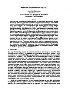
Recent developments in high speed communications technology have resulted in interesting new applications using the integration of voice, video and data. Fiber optics and broadband integrated services digital network (B-ISDN) provide bandwidth and delay characteristics necessary to support these new media. One such application is the distributed multimedia information system (DMIS). This application supports integration and coordination of audio, video, text, and numeric data originating from databases or live, real-world sources interconnected by high-speed networks [39]. One of the requirements of any system supporting time-dependent data is the need to provide synchronization of data elements which experience random delays during transmission and retrieval. In a DMIS, this problem is particularly acute since several streams originating from independent sources can require synchronization to each other, in spite of the asynchronous nature of the network. In addition to the synchronization of live data streams that have an implied temporal correspondence, synchronization is also required for synthetic relationships which impose arbitrary temporal relationships on stored data elements of any media, including audio, video, text, etc. [1]. For example, a single image can be arranged to playout in synchrony with a segment of speech at a multimedia workstation. For supporting the transmission of time-dependent multimedia data, real-time communication protocols and operating systems are essential. These systems assign the utmost priority to the meeting of deadlines for a set of scheduled time-dependent tasks. For multimedia data, catastrophic results do not occur when data are not delivered on time. For these data, real-time deadlines consist of the playout times for individual data elements that can be scheduled based on a specified probability of being missed. The design of a such a system to support time-dependent media must account for latencies in each system component used in the delivery of data, from its source to its destination. Therefore, specific scheduling is required for storage devices, processors, and communications resources. Most work on multimedia synchronization has been published only very recently. This problem is considered an important requirement for multimedia applications [1–12, 14–24, 26, 27, 36, 39, 40]. The work in this area typically applies to live data communications [2–10], data storage systems [1, 11–17], or general distributed systems [1, 8, 18–22]. For data communications, synchronization has typically been applied to live data sources such as packet audio and video [2–10] and requires that channel capacity should not be exceeded over the duration of the session, except in bursts. These applications rely on a pointto-point configuration since there is seldom any need to provide intermedia synchronization of multiple independent live sources. Synchronization at the destination provides smoothing of the packet stream and tracking of the source packet production rate. At the source, data sequencing can ensure equivalent delays for multiple streams for the individual point-to-point connections [23, 24]. Analytical models have been developed for the description of a packet voice receiver (PVR) which reduces the variance of the jitter introduced in an real-time voice stream over a packet network [2–4]. Similarly, models have been developed which, given an error bound, establish the delay introduced to meet the error specification as applied to the analysis of packet video [5]. Feedback and adaptive schemes for tracking of transmitted video in an asynchronous network have also been proposed [6–8]. The goal of these earlier techniques it to reshape the distribution of arriving packets to reduce delay variance. This 2
Delay Probability Density Function
w(t) p(t) Delay
Figure 1: Reduction of arriving packet delay variance. process is shown schematically in Figure 1, where p(t) is the delay density function and w(t) is the reconstructed playout distribution. With respect to communications protocols in the OSI framework, a mechanism is presented in [11] using the synchronization marker (SM) concept for indication of synchronization points and how this can be applied to the OSI reference model. For data sequencing, the multimedia virtual circuit (MVC) [23] has been proposed to guarantee the ordering and delay of synchronized data streams for single point-to-point connections, similar to the approach proposed in [24]. Nicolaou [18] identifies hierarchical levels of data elements for which different degrees of synchronization can be applied. In [1], a unified model is used to bridge the gap between synthetic and continuous synchronization. Karlsson and Vetterli [25] investigate the integration of packet video into the network architecture, noting that the OSI model was not designed to provide real-time transmission. Synchronization is also an important consideration for stored-data applications [1, 11–17]. Audio and video require very large amounts of storage space and will exist, when not live, in secondary storage. When data originate from storage, the system has more flexibility in scheduling the times at which data are communicated to the application. Since data are not generated in real-time, they can be retrieved in bulk, well ahead of their playout deadlines. This is contrasted with live sources, e.g., video cameras, that generate data at the same rate as required for consumption. Unlike live sources, stored data applications in a DMIS can require synchronization for data originating from independent sources, and simple data sequencing cannot provide intermedia synchronization. In a distributed system, the distinction between the network and the storage devices is blurred. The requirements for the support of continuous media in such a system are the topic of [1, 8, 18–22], [26, 27]. Much of this work deals with the management of system resources to provide real-time data delivery. Typically, bandwidth and buffer space are managed via reservation to meet the statistical characteristics of time-dependent data streams. A number of interesting problems remain to be solved to provide a general-purpose application synchronization service within the network architecture. For the network, problems include the specification of protocols to provide synchronization, the monitoring of data traffic for characterization of delays affecting synchronization, and the evaluation of such delays to provide synchronization. Problems for the application service include concurrent managing of multiple synchronized connections, locating multiple sources for composing distributed objects, and maintaining temporal information. Our contribution to the synchronization problem is the development of a theoretical basis for arbitrary synchronization of multimedia data elements and the proposal of a set of protocols for providing this synchronization. We describe how synchronization can be performed
3
within the network, and present a corresponding communication architecture. This work differs from earlier works in the following ways: 1. A single model is developed to handle both continuous and non-continuous synchronization. Accordingly, a set of protocols is specified to enforce synchronization with a desired quality of service (QOS) with respect to delay, bandwidth, and probability of synchronization failure. 2. We assume that data streams can originate from multiple independent stored-data sources in addition to live sources, using multiple physical or virtual channels. 3. A concurrency mechanism for synchronization is proposed, such that streams can be synchronized to a single destination rather than to a single source clock. Most earlier work assumes that the source dictates the playout at the receiver (e.g., [6]). The problem with this notion comes with providing synchronization for two streams originating from independent sources. 4. We use a priori knowledge of data traffic characteristics to facilitate scheduling, when available, rather than providing on-line scheduling of dynamic input data based on its statistical nature (e.g., [19–21]). 5. We do not consider real-time scheduling disciplines for packets, prioritization, etc. (e.g., [20]); rather, we assume that such capabilities are available to the operating system or transport mechanism. The system is assumed to allocate various resources based on their availability, including channel capacity, buffer space, and priority [30]. 6. The dynamic bandwidth requirements of a multimedia object are fit into finite resources (delay and channel capacity) rather than the resources dictating the feasibility of the application, i.e., the inherent burstiness of the object is smoothed via our algorithms (e.g., [26]). 7. Delays are traded off for the satisfaction of a playout schedule, even when the capacity of the channel is exceeded by the application. The remainder of this paper is organized as follows. In Section 2, we discuss theoretical aspects of intermedia synchronization for events and streams. In Section 3, we describe arbitrary intermedia synchronization with Petri nets, their timing analysis, and propose algorithms to facilitate scheduling of synchronization for communication. In Section 4, a set of protocols based on the proposed algorithms is described. Several examples illustrating their utility are presented in Section 5. Section 6 concludes the paper.
2
Intermedia Time Synchronization
The process of synchronization of data in the network consists of the evaluation of the temporal characteristics of the data to set up a connection, and the provision of real-time data transfer and anomaly correction when data are delayed or corrupted. In order to evaluate the temporal requirements of data elements, we must first understand the process 4
T Playout Interval τ
λ φ
time
π
Figure 2: Timing for single event synchronization. p(t)
Source Stream
Packet Network
w(t) Buffer
Destination
Figure 3: Stream synchronization in a network. Packet Production Scheduleπi+7 − T
πi − T
Propagation Delay Delay Variation Control Time T
Playout Schedule (Zero Failures)
πi
πi+7
time
Figure 4: Illustration of incurred packet delays. of scheduling with respect to multimedia objects. In this section, we formalize the process of scheduling events and streams. Subsequently, in Section 3, we describe the synchronization of hierarchies of temporally related data which we refer to as nets.
2.1
Data Synchronization
In order to properly synchronize some data element x with a playout time instant π, sufficient time must be allowed to overcome the latency λ caused by various processes such as data generation, packetization, transmission, etc.; otherwise, the deadline π will be missed. If we choose a time, called the control time, T , such that T ≥ λ, then scheduling the retrieval at T time units prior to π guarantees successful synchronization. The retrieval time, or packet production time, φ, is defined as φ = π−T . The case of synchronizing one event is simply the problem of meeting a single real-time deadline, which is a subset of the real-time scheduling problem. Figure 2 shows the relationships between these aforementioned parameters. For streams of data, the multiple playout times and latencies are represented by Π = {πi } and Φ = {φi }. The general scenario for synchronization of a data stream in a network is shown in Figures 3 and 4. Here, elements of the data stream are generated at a source and experience some random delay with a distribution described by p(t), before reaching their destination. They then require synchronization based on a playout schedule with deadlines πi and playout hold times τi . Further, this problem can be extended from the cases of singular streams of packetized audio and video [2–10] to multiple streams and non-stream data (e.g., still images and text) as we show in Section 3. 5
Cumulative 1 Fraction 1−P (Loss) of PlayedOut Packets Delay
TP (Loss)
Figure 5: Probability distribution for transit delay. Packet Generation Times time Playout Times
Figure 6: Limited channel capacity: Adjustment of retrieval times. For a target packet loss characteristic, the control time T can be found for stream types using various approaches [2], [5], and represents the time required for buffering at the receiver to smooth variations in latencies λi . These variations in λi , as well as in τi , result in a shortterm average or instantaneous need for buffering. For live sources, playout duration times are typically uniform (τi = τj , ∀i, j) and delay variation governs the buffering requirement. For the general case, we are presented with arbitrary streams characterized by πi , λi , and τi , and would like to determine the amount of buffering necessary to maintain synchronization with a given probability of failure. In Figure 5, we illustrate a cumulative probability distribution function for packet transit delay through a network, showing how the control time T can be evaluated from the endto-end delay distribution at some probability of packet loss. The resultant T represents the end-to-end delay required to meet the specified loss characteristic. There is a tradeoff between this delay and packet loss since a large delay is not satisfactory for most real-time broadband streams (e.g., voice or video conversations), and packet loss introduces problems of data reconstruction (see Section 3.5). Also, since the delay distribution can change with time, the loss specification can be violated given a constant T [7]. One of the assumptions in the earlier analyses is that the generation of packets is at a rate equal to the consumption rate as is typical for live sources. When we consider a database as the source of a packetized stream instead of a live source (e.g., camera), the packet generation can be greater than the consumption rate for some intervals and less for others, due to the adjustability of the data retrieval rate (see Figure 6). In essence, data storage sources give us more freedom in controlling the packet production times. This is particularly important when we require concurrency in the playout of multiple media, as described in Section 3.
2.2
Multiple Stream Synchronization
Intermedia synchronization is the temporal coordination of multiple streams relative to one another, and requires concurrent streams to be played out at identical synchronization times πi . Since it is desirable to transmit streams independently [28, 30], we decompose multiple 6
streams into single ones for the purpose of identifying individual control times. However, data streams possessing the same schedule in terms of playout times may not necessarily produce identical T ’s nor will they require the same buffering. This occurs since the streams can represent different classes of data in the network, and can have a different fixed delay component due to differing data size. To maintain intermedia synchronization, each stream must experience the same overall delay to avoid skewing. Adaptive schemes are unsatisfactory for this purpose since control times for multiple channels would necessarily adapt to their corresponding channel delays rather than to a single overall delay. Since intermedia synchronization is ultimately desired, to synchronize multiple streams, the control times of each stream must be accommodated, i.e., each stream must be delayed as long as the largest T . Nevertheless, the required buffering for each stream need not conform to the worst control time.
3
Multimedia Object (Net) Synchronization
In this section, we generalize the idea of synchronization to composite multimedia objects and present algorithms for generating schedules for object presentation and communication, which are the basis for the protocols of Section 4.
3.1
Temporal Specification Using Petri Nets
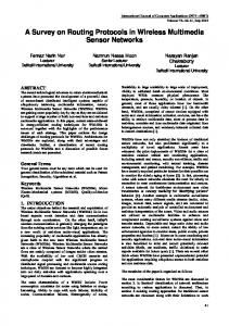
Suppose that a multimedia object is comprised of data elements x, y, and some stream S, and requires synchronization at txi and tyi . These temporal relationships are difficult to capture with the stream semantics. A more general method to specify synchronization and the relationship between data elements uses a form of Petri net called the object composition Petri net (OCPN) [12]. The OCPN has been demonstrated to capture all possible temporal relationships between objects required for multimedia presentation [12]. The salient features of the OCPN are described as follows. The OCPN is defined as a bipartite directed graph NOCPN , specified by the tuple, {T, P, A, D, R, M } where: T = {t1 , t2 , . . . , tn } is a set of transitions (bars) P = {p1 , p2 , . . . , pm } is a set of places (circles) A : {T × P } ∪ {P × T } → I, I = {1, 2, . . . } is a set of directed arcs (arcs) D : P → R is a mapping from the set of places to the real numbers (durations) R : P → {r1 , r2 , . . . , rk } is a mapping from the set of places to a set of resources M : P → I, I = {0, 1, 2, . . . } is a mapping from the set of places to the integers. In this context, we assume that the resource component of the Petri net indicates a DMIS component which requires shared usage. For example, resource r1 can indicate video data obtained from a specific database and communication channel. In this manner, network data traffic can be described based on its source and type, and can be associated with 7
t1 pinitial
t2 τ p1
t3 τ p2
t4
t5
τ p3
τ p4
t6 τ p5
t7 τ p6
pfinal
(a) τ p1 t1 pinitial
τ p2 p τ 3
t2 pfinal
τ p4 τ p5 (b) t1
τ τ
paudio t2 pvideo
(c)
Figure 7: (a) Sequential OCPN. (b) Concurrent OCPN. (c) OCPN template. specific channel delay and capacity requirements. With the OCPN, we are free to choose the granularity of synchronization by assignment of time durations to the places. Associated with the definition of the Petri net is a set of firing rules governing the semantics of the model as follows: 1. A transition ti fires immediately when each of its input places contain an unlocked token. 2. Upon firing, the transition ti removes a token from each of its input places and adds a token to each of its output places. 3. After receiving a token, a place pj remains in the active state for the interval specified by the duration τj . During this interval, the token is locked. When the place becomes inactive or upon expiration of the duration τj , the token becomes unlocked. In Figure 7(a)–(c), examples of three OCPN’s are shown, representing sequential and concurrent presentation of objects (e.g., video frames and still color images, respectively), and an OCPN template for synchronous live audio and video. The OCPN template allows characterizing live sources with representative or worst-case playout durations and object sizes. These examples illustrate the strict and partial ordering that exists for various temporal relations among objects, and illustrates the possible flexibility in terms of deriving a retrieval sequence for the objects.
8
3.2
Playout Deadline Generation
Since an OCPN can easily represent synchronization of simple events and streams, we seek to determine playout times given the precedence relations and playout durations captured by the OCPN. These times then allow us to determine deadlines for data retrieval, and to identify the necessary buffering required. We propose the serialize-net algorithm for this purpose. An algorithm is also presented which decomposes a schedule into multiple playout subschedules formed by the elements unique to each traffic class or resource. This is called the resource-decomposition algorithm. Serialize-Net Algorithm: π1 = 0 new marking = true while new marking new marking = false for each transition ti in T if M (pj ) > 1, ∀j : A(pj , ti ) > 1 then new marking = true M (pj ) = M (pj ) − 1, ∀j : A(pj , ti ) > 1 M (pk ) = M (pk ) + 1, ∀k : A(ti , pk ) > 1 sti = max({πj + τj }), ∀j : A(pj , ti ) > 1 πk = sti , ∀k : A(ti , pk ) > 1 end end end
{start at time = 0}
{enabled transition} {create new marking} {transition time} {playout time}
The serialize-net algorithm simulates an OCPN as follows. Beginning from the initial marking (M (pinitial ) = 1 and M (pi ) = 0, ∀i (1 < i ≤ pfinal )), the firing rules are obeyed, i.e., all enabled transitions fire, thus creating new markings. As new markings are created, the start times of enabled transitions are identified as well as the start times of output places. The algorithm iterates until no new markings can be created, is only appropriate for marked graphs (a subset of Petri net models of which the OCPN is a member), and is guaranteed to terminate since the OCPN is acyclic [12]. Table 1 shows the evolution of the markings for the OCPN of Figure 7(a), assuming a video rate of 30 frames/second. For this example, the resultant schedule is Π = {0.0, 0.033, 0.067, 0.1, 0.133, 0.167} seconds. For Figure 7(b), Π = {0, 0, 0, 0, 0, 0} seconds. These schedules represent the sets of deadlines for playout of data elements specified for each OCPN. Once serialization is complete, a playout schedule can be decomposed into subschedules for each resource rk , e.g., for each traffic class. The following resource-decomposition algorithm decomposes the different resource components, and creates multiple schedules representing subsets of the original:
9
Resource-Decomposition Algorithm: for all places pi in P if R(pi ) = rk then Π(rk ) = Π(rk ) + πi i(rk ) = i(rk ) + 1 end end
{identify places} {add to schedule} {increment subschedule count}
For example, this algorithm iterates through the set of audio/video deadlines in Π in the creation of subschedules Πaudio and Πimage representing the deadlines of distinct classes of data. For nets, like streams, we need to determine the amount of buffering required for a specific probability of synchronization failure. Presentation concurrency can be serialized and resources can be decomposed, creating multiple schedules (one per resource). The amount of buffering and corresponding delay can then be determined for each subschedule. We have thus reduced the general synchronization problem to independent cases as described in Section 2.2.
3.3
OCPN Scheduling and Control Time Generation
After the net has been serialized and decomposed into classes, a control time must be determined for each subschedule. In previous work, live sources have been studied in which the packet generation times simply track the playout times with an introduced control time [2–5] or, if φi are the packet production times, then φi = πi −T , ∀i, where πi are the playout times. The playout sequence is merely shifted in time by T from the generation time, as shown in Figure 4. This constant timeskewing is possible since it is assumed that the channel capacity is never exceeded. However, for some stored-data applications, it is permissible for the OCPN playout schedule to specify retrieval of data exceeding the available channel capacity (e.g., see Figure 8), and the previous scheduling policies are deficient [2–10]. Instead, we propose the deriving of a schedule that utilizes the full capacity of the channel by providing buffering at the destination based on a priori knowledge of the playout schedule Π. 3.3.1
Timing Analysis
We decompose the total end-to-end delay for a packet into three components: a constant delay Dp , a constant delay Dt proportional to the packet size, and a variable delay Dv which is a function of the end-to-end network traffic. Dp corresponds to propagation delays and
Channel Backlog
c scheduled playouts πi
time
Figure 8: Back-to-back arrivals for concurrency. 10
other constant overheads (“pipeline” delay). Dt is determined from the channel capacity C as Dt = Sm /C, where Sm is the packet size for medium m. Dv is a variable component determined by channel traffic. Therefore, Dend-to-end (packet) = Dp + Dt + Dv , for individual packets for size Sm . (1) A typical data object consists of many packets. Let |x| be the size of object x in bits. The number of packets r required for object x is determined by r = d(|x|/Sm )e. The end-to-end delay for the complete object x is then Dend-to-end (object) = Dp + rDt +
r X
Dvj .
(2)
j=1
Define control time Ti to be the skew between putting an object (packet) onto the channel and playing it out (Ti = πi − φi ). Determination of a Ti is based on a selected probability of a late packet, called P (fail). Given P (fail) and the cumulative distribution function F of interarrival delays on the channel (of the random variable Dv ), we can readily find Ti for a single packet using (1), as shown in (3). For an object comprised of multiple packets, Ti can be determined from (2), as shown in (4). Ti = Dp + Sm /C + F −1 (1 − P (fail)), for individual packets, and Ti = Dp + ri Sm /C + Fr−1 (1 − P (fail)), for single objects,
(3) (4)
−1 where F −1 (p) determines the delay Pr d for p = F (d) = P (Dv ≤ d), and Fr (p) determines the delay d for p = Fr (d) = P ( j=1 Dvj ≤ d). Since Fr (d) requires a convolution on r random variables, it is computationally impractical for an arbitrary distribution on Dv when r is large. However, in this case we can use a Gaussian approximation for the distribution of a sum of r independent random variables, as justified by the Central Limit Theorem. Given the mean µ and variance σ 2 of the interarrival distribution, we can use the equivalent Gaussian approximation and determine the desired delay for the prespecified probability of synchronization failure. For a set of multiple objects, it is possible to exceed the capacity of the channel and therefore we must consider their interaction. Depending on their size and playout times, transmission of objects is either back-to-back or introduces slack time. We define an optimal schedule for a set to be one which minimizes their control times. Two constraints determine the minimum control time for a set of objects:
πi ≥ φi + Ti φi−1 ≤ φi − Ti−1 + Dp
(5) (6)
where i ranges over the set of objects, and corresponds to monotonically increasing deadlines. Constraint (5) describes the minimum end-to-end delay per object. It simply states that an 11
φi−1 Dti−1
Ti−1 πi−1 Dvi−1 Dp φi
Dvi Dp πi
Ti
φi Time
πi
Ti Dti
Dti
Dvi Dp
Figure 9: Schedule constraints. object cannot be played out before arrival. This constraint must always be met. Constraint (6) describes the relation between a retrieval time and its successor when the channel is busy and accounts for the interarrival time due to transit time and variable delays (bandwidth constraint). This represents the minimum retrieval time between successive objects. The following theorem combines these results and describes the characteristics of an optimal schedule (see Figure 9). Theorem 1 An optimal schedule for any object i has the following characteristics: ∀i, φi ≥ πi−1 − Dp ⇒ φi−1 = πi−1 − Ti−1 , and φi < πi−1 − Dp ⇒ φi−1 = φi − Ti−1 + Dp . Proof Any object in the set can find the channel idle or with a backlog of items. If it is slack, the equality of (5) is optimal, by definition. Similarly, when the channel is busy, the equality of (6) is optimal. Clearly, a channel is slack when φi occurs after πi−1 , but it can also be slack when φi ≥ πi−1 − Dp due to the pipeline delays. Therefore, the state of the channel, idle or slack, can be identified. We now show how to construct such a schedule as follows. Given Dv , Dp , Dt , C, Sm , πi , |xi |, we wish to construct an optimal schedule Φ = {φi }. We work backwards and begin by establishing an optimal retrieval time for the final mth object, i.e., φm = πm − Tm . The remainder of the schedule can be determined by iterative use of Theorem 1. The skew between playout and retrieval times for each object is now influenced by other objects using the channel, and is given by debti = πi − φi . The buffer space requirement at any given fetch time corresponds to debti , and is determined by the number and size of object retrievals completed between πi and φi . Note that an optimal schedule need not be unique since multiple playout deadlines can share the same value (playout deadlines can form a partial order). The ensuing net-control-time algorithm computes the retrieval schedule as follows.
12
Net-Control-Time Algorithm: φm = πm − Tm for i = 0 : m − 2 if φm−i < πm−i−1 − Dp then φm−i−1 = φm−i − Ti−1 + Dp else φm−i−1 = πm−i−1 − Tm−i−1 end end
{work backwards} {busy channel}
{idle channel}
We can also determine the number of buffers required when using the playout schedule Φ, again noting that it is necessary to obtain an element prior to its use. For each fetch time φi , the number of buffers, Ki , required is equal to the size of the objects with elapsed playout deadlines between φi and πi−1 . The following buffer-count algorithm can be used for this purpose. Buffer-Count Algorithm: K1 = 0 for i = 0 : m − 2 Km−i = 0 j=i while (j < m − 1) and (φm−i < πm−i−1 ) {count lagging playout periods} Km−i = Km−i + |xm−j−1 | j =j+1 end end From these algorithms we can determine the buffer use profile, φi versus K, and the maximum delay, debt, incurred by this buffering, which can be used for allocation of storage. Referring to the example OCPN’s of Figure 7, retrieval schedules and buffer use profiles are generated assuming the following conditions: C = 45 Mb/s, Sm = 8192 bits, Dv = 50 µs, and Dp = 100 µs. For Figure 7(a), τi = 1/30 s and |xi | = 220 bits, corresponding to compressed video frames. For Figure 7(b), τi = 20 s and |xi | = 1024 × 1024 × 24 bits, corresponding to color images. The results of the net-control-time and buffer-count algorithms are: Case (a): Φ = {−0.0298, 0.0035, 0.0369, 0.0702, 0.1035, 0.1369} s, K = {0} Mb Case (b): Φ = {−3.56, −2.85, −2.14, −1.43, −0.71} s, K = {24, 48, 72, 96} Mb. These results indicate that there is ample time to transmit the specified video traffic without buffering beyond the object in transit [case (a)], and that the image traffic requires 3.56 s of initial delay and up to 96 Mb of buffering at 0.71 s prior to initiating playout [case (b)]. From our discussion, we indicate that the solution to the synchronization problem lies in proper selection of control time for independent classes of data. However, we must consider 13
practical considerations for determining network delay distributions and the handling of data lost in the network, which is described next.
3.4
Implementation of Schedules and Tradeoffs
In this section, we show how the schedules and control times can be used on a point-to-point basis. Basically, we can use the derived schedule Φ in two ways. First, the data source or transmitter can use it to determine the times at which to put objects onto the resource (channel). The receiver can then buffer the incoming objects until their deadlines occur. In this case the source must know Φ, the destination must know Π, and the overall control time is T1 , the computed delay of the first element in the sequence. This scheme can be facilitated by appending πi onto objects as they are transmitted in the form of timestamps. The second way to use Φ is to determine the worst-case skew between any two objects as Tw = max({πi −φi }), and then to provide Tw amount of delay for every object. Transmission scheduling can then rely on a fixed skew Tw , and the Π schedule; that is, transmit all items i such that (t ≤ πi ≤ t + Tw ). The first method minimizes both buffer utilization and delay since the schedule is derived based on these criteria. Furthermore, required buffer allocation need not be constant, but can follow the buffer use profile. The second method provides unnecessary buffering for objects, well ahead of their deadlines, and requires constant buffer allocation. However, it provides a simpler mechanism for implementation as follows. Consider a long sequence of objects of identical size and with regular (periodic) playout intervals. For this sequence, T1 = Tw , and φi = πi − Tw , assuming the channel capacity C is not exceeded. In this case, the minimum buffering is also provided by the worst-case delay. Such a sequence describes constant bit rate (CBR) video or audio streams which are periodic, producing fixed-size frames at regular intervals. Rather than manage many computed deadlines/second (e.g., 30/second for video), a transmission mechanism more simply transmits objects based on sequence number and Tw . When data originate from live sources, the destination has no control over packet generation times, and sufficient channel capacity must be present to preserve the real-time characteristic of the streams. In this case, the control time can be determined from the size, delay, and channel capacity requirements of a representative data object, e.g., a CBR video frame as described by an OCPN template, and only provides jitter reduction at the receiver. For variable bit rate (VBR) data sources, the data stream is statistical in size and frequency of generated objects, and we apply a pessimistic worst-case characterization of the largest and most frequent VBR object to determine the control time. {φi } defines the packet production times, and playout times are determined by πi = φi + T , as done in previous work. This service is supported in our protocols by appending timestamps, in the form of individual deadlines, πi , to the transmitted objects. In the general case, a playout schedule is aperiodic, consisting of some periodic deadlines and others aperiodic. Typically, during class decomposition, these are isolated, and one of the two scheduling schemes above can be applied. If both exist in the same playout schedule Π (e.g., if classes are not decomposed), then the derived schedule Φ can be used as follows: choose a new control time TE such that (T1 ≤ TE ≤ Tw ), and drop all deadlines φi from Φ such that TE ≥ πi − φi . The result is a culled schedule Φ reflecting the deadlines that will not be satisfied by simply buffering based on TE . By choosing TE to encompass a 14
periodic data type (e.g., video), the burden of managing periodic deadlines is eliminated, yet aperiodic objects, requiring extensive channel utilization, can be dealt with using φi − TE , where φi − TE > 0. When multiple delay channels are cascaded, e.g., channel delays plus storage device delays, we see that the end-to-end path capacity is reduced to the value of the slowest component. To facilitate scheduling of each resource, we can apply the derived schedule Φ of the first channel as the playout schedule of the succeeding channel, while moving towards the source. In this manner, each resource merely meets the schedule stipulated by the preceding resource in the chain; with the initial schedule being Π. For this scheme, however, to meet the same P (fail), the failure probability used for computing Φ on each link must be divided between each component [27].
3.5
Synchronization Anomalies
Anomalies in synchronization for sequences of objects can be introduced due to inability to meet synchronization deadlines, by loss, and by corruption of data in the network. Suitable policies must be developed to remedy this situation and yet still attempt to satisfy ongoing deadlines of subsequent objects. Retransmission protocols are not applicable to real-time data since they introduce unreasonable delay. At the presentation device, a synchronization failure can result in a shortage of data to playout per unit time, resulting in a gap. A shortage of data can be caused by differences in source and destination clocks. Typically, the destination clock tracks the source clock in a point-to-point configuration for audio and video sources [5–7]. However, a single destination cannot track multiple source clocks and also provide intermedia synchronization when the source clocks are independent. For the proposed protocols, we assume that the destination controls the clock rate of the sources either via a global clock, periodic drift correction [31–34], or by using feedback [6, 35]. Various approaches have been investigated for the reconstruction of a playback sequence with gaps, e.g., extending the playout time of the previous element [36], or interpolation of earlier values [37]. When gaps in a data sequence are ignored with respect the playout rate, the loss of data elements when subsequent data are available advances the sequence in time, and can be corrected by slowing the playout rate until the schedule is correct [1, 7]. For the proposed protocols, the playout of arrived data elements is determined entirely by the derived schedule. Data are released for playout at the indicated deadlines. Although we do not propose a specific gap-compensating scheme, a suitable one can be chosen such as sample interpolation [37].
4
Proposed Protocols for Synchronization
In this section, we propose a set of protocols for providing synchronization of objects as a network service which are practically implementable. We distinguish two levels of synchronization to support general-purpose network service and application service. At the network service level, a service interface is provided to support applications requiring synchronization of sequences of single-class data traffic. This interface takes sets of data elements and their playout schedules and provides a synchronized output. At the application service level, 15
Application
Application
ASP
ASP
NSP
NSP
Local OS Data storage
Transport
Transport
Physical Data Communication
Local OS Data storage
Figure 10: Relationships between synchronization components. temporal information in the form of an OCPN is utilized to produce playout schedules for synchronized communication of multiple classes of data with a specified P (fail). By decoupling the network and application components, the network service only requires knowledge of deadlines and traffic class rather than data source locations, temporal relations, and object composition sites within the network [39]. We propose two synchronization protocols corresponding to these levels: the application synchronization protocol (ASP) and network synchronization protocol (NSP). The relationship between these layers, the application, and the transport mechanism, is shown in Figure 10. Later, in Section 4.3, we indicate how these protocols are mapped onto the framework of the OSI reference model.
4.1
Network Synchronization Protocol (NSP)
To provide a general interface and functionality to support applications requiring time synchronization, we require that the protocol take as input a set of objects Oi , their playout times πi , their aggregate start time, and the desired probability of synchronization failure. The protocol can then provide us with the following: 1. A predicted end-to-end control time T for the set of data elements. 2. A point-to-point data transport mechanism. 3. Resynchronization and anomaly correction. 4. Signaling from destination to source to control playout rate. We now discuss individual components required to construct the NSP. 4.1.1
NSP Service Primitives
From an end-to-end perspective, the control time for a sequence Π depends on the sequence itself, the interarrival distribution of consecutive packets, and any delays (e.g., a local control time) introduced in procuring the data at the source. If we can characterize these delays, then the control time can be determined using the procedure outlined in Section 3.3. For the NSP’s, we assume that the network delays can be characterized by either measurement techniques [4, 29] or by guaranteed quality of service offered at access to the 16
ASP ASP-estab-conn Interface ASP-initiate-transfer Primitives ASP-release-conn Get-net Local Serialize-net Resource-decompose Primitives NSP NSP-estab-conn NSP-start-transfer NSP-release-conn
Interface Primitives
Buffer-count Net-control-time
Local Primitives
Transport Mechanism Reserve Release
Interface Primitives
Figure 11: Summary of ASP, NSP, and transport interface primitives. network [30]. For example, statistical data characterizing throughput, time delay, arrival rate, interarrival rate, and buffer occupancy can be collected using a hardware observational mechanism [28–30]. A network access mechanism can use these collected data for resource allocation decisions when setting up a connection. New connections can be accepted or refused based on available bandwidth or delay characteristics. When accepted, the access mechanism guarantees that the network is able to provide the requested level of service for a connection since system congestion is prevented by limiting additional connections. For synchronization purposes, a guaranteed level of service provides a well-defined characterization of the channel that the NSP can easily deal with. We therefore assume, for the NSP, that the underlying network transport and multiplexing mechanism provides a characterization of interarrival distributions of consecutive packets through a service interface on a per-connection basis. At the time of connection establishment, given a class of traffic, source and destination pair, channel capacity, packet size, and late packet probability (corresponding to P (fail)), the access mechanism returns the channel delays and the mean and variance of the interarrival time of consecutive packets. We perceive this access mechanism to work equally well on network resources as well as operating system resources including database and storage subsystems. Accordingly, we define interface primitives for this service as follows. [Dp , Dt , µ, σ 2 , resource-id, r-avail] = reserve(class, source, dest, P -late, C, Sm ) release(resource-id ) 17
The reserve primitive requests network services of a specific class and probability of having late or lost arrivals. The returned parameters, Dp , Dt , µ, and σ 2 describe the channel delays, and the mean and variance of the interarrival time. If the resources are not available for this connection, the Boolean variable r-avail is returned false, indicating a refused connection. The resource-id simply identifies the reserved resources. Corresponding to the reserve interface primitive, a resource deallocation interface primitive is required. The functionality of this procedure is to release previously reserved resources for subsequent connections. With the parameters returned from reserve and a schedule Π, we employ the algorithms of Section 3.3 as internal NSP primitives as follows. [TE , Φ] = net-control-time(Dp , Dt , µ, σ 2 , Π) [K] = buffer-count(Φ, Π) The NSP supports a calling ASP entity by several service primitives. These primitives are defined for connection establishment, termination, and data transfer initiation (see Figure 11). The primitives utilize the internal NSP primitives defined above and the reserve primitive of the transport mechanism to provide the network synchronization service. Note that the primitives can be invoked by the local process or by remote peers. For connection establishment, the NSP-estab-conn provides channel setup for synchronization service and is defined as follows: [TE , K, NSP-conn-id, NSP-avail] = NSP-estab-conn(class, source, dest, P -late, Π). The steps involved in connection establishment are as follows: 1. Receive (class, source, destination, P -late, Π). 2. If remote source (source 6= destination = my-site-id) then: Invoke remote peer using [TE , K, NSP-conn-id, NSP-avail] = NSP-estab-conn(class, source, my-site-id, P -late, Π). If resources are available (NSP-avail = true) then: Allocate and initialize K receive buffers. 3. If remote destination (source = my-site-id 6= dest), then: Reserve channel resources using [Dpc , Dtc , µc , σ 2c , resource-idc , r-availc ] = reserve(class, source, P -late). If channel resources are not available (r-availc = false) then: Set NSP-avail = false to indicate lack of resources. Release the resources using release(resource-id c ). Otherwise (r-availc = true): Derive channel schedule using [TEc , Φc ] = net-control-time(Dpc , Dtc , µc , σ 2c , Π). 18
Determine channel buffer utilization using [K c ] = buffer-count(Φc , Π). Allocate and initialize K c receive buffers for the channel. Reserve storage resources using [Dps , Dts , µs , σ 2s , resource-ids , r-avails ] = reserve(class, source, P -late). If storage resources are not available (r-avails = false) then: Set NSP-avail = false to indicate lack of resources. Release the resources using release(resource-id s ) and release(resource-id c ). Otherwise (r-avails = true): Derive combined storage schedule using [TEs , Φs ] = net-control-time(Dps , Dts , µs , σ 2s , Φc ). Determine storage buffer utilization using [K s ] = buffer-count(Φs , Φc ). Allocate and initialize K s receive buffers. Overall delay is the sum of storage and channel delays, TE = TEs + TEc . Set NSP-avail = true. 4. If local source and destination (source = dest = my-site-id) then: Reserve storage resources using [Dps , Dts , µs , σ 2s , resource-ids , r-avails ] = reserve(class, source, P -late). If storage resources are not available (r-avails = false) then: Set NSP-avail = false to indicate lack of resources. Release the resources using release(resource-id s ). Otherwise (r-avails = true): Derive storage schedule using [TEs , Φs ] = net-control-time(Dps , Dts , µs , σ 2s , Π). Determine storage buffer utilization using [K s ] = buffer-count(Φs , Π). Allocate and initialize K s receive buffers. Indicate overall delay TE = TEs . Set NSP-avail = true. 5. Return [TE , K, NSP-conn-id, NSP-avail] to the calling entity. The propagation of computed control times and schedules is illustrated in Figure 12. In this case the computation of the retrieval schedule for the storage device (Φs ) applies the retrieval schedule of the channel (Φd ) rather than Π, as indicated in Section 3.4. The NSP-release-conn(NSP-conn-id ) provides an interface primitive for the ASP to terminate connections and release to resources. This primitive operates as follows: 19
To ASP TEc + TEs NSP Π TE
virtual circuit
NSP Φc TEc
server
Storage Φs TEs
Figure 12: Propagation of control times to the ASP. 1. release(NSP-conn-id.resource-id ). 2. Return. Once a connection is established, the NSP must initiate data transfer based on the computed control times and perform the actual data transfer. An interface to the NSP for initiating data transfer and synchronization is defined as NSP-start-transfer (start-time, NSP-conn-id ), and operates as follows: 1. Receive (start-time). 2. Pass (start-time-NSP-conn-id.TE ) to peer NSP-start-transfer interface specified by NSP-conn-id.source. Once initiated, the data transfer protocol sends data, via virtual circuits and the underlying transport mechanism to the destination’s buffers. The steps are: 1. At time = start-time, set transmit clock, transmit clock, to zero. 2. ∀i, φi = transmit clock, send object i to the destination with appended playout deadline πi . 3. ∀i, (transmit clock ≤ πi ≤ transmit clock + TE ) send object i to the destination with appended playout deadline πi . 4. Repeat steps 2 and 3 until Π is exhausted. The protocol at the receiving site receives the data, providing buffering at a location specified by NSP-conn-id.buffer. Data are released to the application at times indicated by the appended deadlines πi . Note that step 3) can be optimized for data with periodic playout times rather than the playout times of Π, as indicated in Section 3.4. An example of the application of this protocol is described in Section 4.3. In the next section, we describe the services provided by the application level and show how they interact with the NSP.
4.2
Application Synchronization Protocol (ASP)
By partitioning the network and application levels we provide two levels of utility for which different applications may be built. This division exposes possibilities for interesting issues such as multihop, multimedia composition and load sharing in a homogeneous system [14]. Like the NSP, we propose a protocol for the application level (ASP). The NSP provides a 20
general interface and functionality for many applications. On the other hand, the ASP provides specific services pertaining to the retrieval of complex multimedia objects from multiple sources across a network for playout at a single site. The ASP interface to the application takes as input a selected object representing the aggregation of complex multimedia presentation requiring synchronization, and return streams of distinct synchronized data traffic which can then be routed to specific output (workstation) devices for presentation. The interface also provides control over the quality of transmission service by specification of packet loss probability. A typical application can use the synchronization service for stored, pre-orchestrated presentations or for live sources such as videophones. For these applications, a temporal specification can be maintained in a database describing the object whether live or stored. Once an object is identified, the remaining steps required to retrieve and present the sought multimedia object are provided by the ASP. The overall processes needed for this purpose are as follows: 1. Retrieval of the temporal relationships describing the components of the complex multimedia object. 2. Evaluation of the precedence relationships of the OCPN, thereby creating a playout schedule. 3. Decomposition of the schedule into subschedules based upon the different traffic classes represented and the locations of stored data. 4. Determination of the overall control time required to maintain synchronization among the traffic classes through interaction with the NSP. 5. Initiation of data transfer. Here we assume that all composition and synchronization is performed at the destination. It is also possible to perform composition at intermediate sites within the network, prior to transmission to the final destination [39]. For stored data, the process of identifying an object from a database is application-specific and consists of browsing or querying using database operations. Once an object is identified, the attributes describing its components and their temporal relationships can be retrieved in the form of an OCPN for schedule evaluation. Given the net N0 representing the time-ordering of object O, we can create a schedule Φ using the serialize-net algorithm of Section 3.3. Recall that the resource-decomposition algorithm can convert this net into a set of subschedules based on the resource component, R, of the net. Each schedule Π(p, q), represents the playout deadlines for all data elements of a resource rj specifying the medium-location pair (p, q). Once the set of schedules is created from Π, the NSP can be initiated for the determination of control times for each rj . In response to invocation, the multiple calls to NSP-estab-conn return multiple responses indicating the control times TE (p, q) and whether the required resources are available. The ASP must then determine the appropriate overall control time, and specify the time to initiate data transfer at all sites. If resources are available, the overall control time T0 , is
21
found as max({TE (p, q), ∀rj , (1 ≤ j ≤ n)}. T0 represents the maximum control time of all paths from data sources to the single final destination. Once T0 is determined, the NSP sessions must be notified as to when to initiate their data transfer schedules. Transfer is initiated by passing the time to start to the NSP-starttransfer interface for each connection defined by rj . The overall control time is added to the current local clock and passed to each interface as clock +T0 . Within the NSP, local control times are subtracted from this overall start time to determine local start times. Each NSP transfer protocol starts data transfer at a time equal to the overall start time minus its own control time. After initiation, multiple invocations of the NSP transfer data from sources to the destination with attached deadlines for playout. At the receiver (destination), the arrived data are released to the application process per the individual schedule, to be routed to the appropriate output device. For applications requiring intermedia synchronization of live sources, e.g., audio and video of videotelephony applications, playout deadlines are generated on-the-fly from the stream of packets emanating from the source, and requires sufficient channel capacity to be available. The ASP and NSP can accommodate these sources as discussed in Section 3.4: the worstcase object size and the shortest playout duration are applied to the ASP in the form of an OCPN template, which describes only the representative classes of data of the objects requiring intermedia synchronization. The ASP and NSP treat the OCPN template like any other object, returning a control time that provides compensation only for random channel delays for traffic specified by the template. 4.2.1
ASP Service Primitives
The ASP is developed in accordance with the requirements of both live and database sources. The following are the definitions of the various internal service primitives required by the ASP as specified by algorithms of Section 3.2: [{T, P, A, D, R, M }] = get-net(object) [Π] = serialize-net(T, P, D, A, M, L) [{Π(r1 ), Π(r2 ), . . . }] = resource-decompose(Π, R). The ASP provides a service through application-ASP interface primitives. These primitives are ASP-estab-conn, ASP-initiate-transfer, and NSP-release-conn defined appropriately for connection establishment, data transfer initiation, and connection release. These primitives utilize the internal ASP primitives defined above and the NSP to provide the application synchronization service. Each primitive is described below. The ASP-estab-conn primitive sets up connections. It is defined as: [ASP-conn-id, ASP-avail] = ASP-estab-conn(object, P -late) The steps involved in ASP connection establishment are summarized as follows: 1. Receive (O, P -late). 2. Identify the OCPN specification for the object using [{T0 , P0 , A0 , D0 , R0 , M0 , L0 }] = get-net(object), where L0 is the set of storage locations of O’s components. 22
3. Generate the playout schedule for the net using [Π] = serialize-net(T0 , P0 , D0 , A0 , M0 ). 4. Decompose the objects components into distinct traffic classes using [{Π(r1 ), Π(r2 ), . . . }] = resource-decompose(Π, R0 ). 5. For each resource rk : Establish a session for the subschedule Π(rk ) using [TE (rk ), K(rk ), NSP-conn-id(rk ), NSP-avail(rk )] = NSP-estab-conn(class, my-site-id,L0 (rk ), P − late, Π(rk )) 6. If resources are not available for any traffic class (any NSP-avail(rk ) = false) then: Set ASP-avail = false to indicate lack of resources. For each resource rk : Release the resources using NSP-release-conn(NSP-conn-id(rk )). 7. Otherwise (all NSP-avail(rk ) = true) Set ASP-avail = true to indicate avaiable resources. Determine the overall control time as T0 = max({TE (r1 ), TE (r2 ), . . . }). 8. Return [ASP-conn-id, ASP-avail ] to the calling entity. For ASP resource deallocation, ASP-release-conn(ASP-conn-id ) primitive can be used by a calling application to terminate a session, such as the reception of the last object in a sequence. This primitive operates by invoking NSP-release(NSP-conn-id ) at both source and destination buffers for each ASP-conn-id.NSP-conn-id. For data transfer initiation, the primitive, ASP-start-transfer (ASP-conn-id ) primitive is defined and operates as follows: 1. Set start-time = current-time + ASP-conn-id.T0 . 2. For each connection, pass (start-time) via NSP-start-transfer interface, initiating data transfer. The destination receives data at buffers set up by calls to the NSP and specified by ASPconn-id.NSP-conn-id.buffer. The receive function provides rerouting of the arriving data to the appropriate application presentation devices, beginning at current-time = start-time+T0 . At the source side, data is fed to the NSP buffers from the live input or database.
23
OSI Reference Model Application Application Layer ASP Presentation Layer NSP
Session Layer
Application and Network Synchronization Components
Transport Layer Network Layer Data Link Layer Physical Layer
Figure 13: Mapping of the ASP and NSP to the OSI reference model.
4.3
Mapping of the ASP and NSP onto the OSI Framework
The ASP and NSP provide two levels of synchronization. Figure 13 shows a proposed mapping of these protocols to the OSI reference model, and their relationship to the network traffic monitoring and access mechanism. The NSP is mapped into the session layer (layer 5). This selection is made since the session layer deals with end-to-end connection establishment, authentication, binding, etc. The NSP synchronization service functions on a per-connection basis requiring the same level of service. This choice is consistent with other proposed and established placements of a synchronization service ( [11] and [40], respectively), although other choices have been proposed as well. In [25], the Presentation layer (layer 6) is suggested as the layer for resynchronization of packet video transmission services, while the session layer provides QOS tuning. In [18], both the presentation and session layers are represented as providing some component of synchronization service at a coarse granularity. For the ASP, we note that cross connection required for intermedia synchronization is not mentioned in the OSI standards for layers 1–6 [11]. Therefore, the intermedia synchronization functionality of the ASP is mapped to the application layer. Other characteristics of the ASP including maintenance of temporal information and database management of objects is clearly a subset of the application level specification. The remaining lower layers of the OSI (layers 1–4) are responsible for data transport, routing, multiplexing, access control, traffic monitoring, etc.
5
Example: The Anatomy & Physiology Instructor
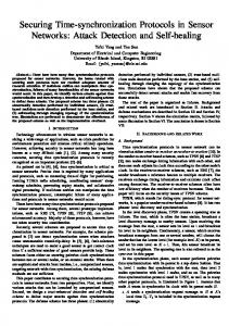
In this section we consider an example to illustrate the use of the NSP and ASP. The Anatomy & Physiology Instructor is a multimedia application example requiring synchronization of stored data [12] in which a “student” may browse through information units (IU’s) on various topics, reading text, viewing illustrations and audio/video presentations, as shown in Figure 14. In addition, the user may perform queries or searches to locate specific topics by using a browsing map [12]. Synchronization is required for elements of text, image, audio, 24
Text:
Full Motion Video: Aortic Stenosis Mitrial Regurgitation Aortic Regurgitation Mitrial Stenosis
Audio: Phonocardiograms: Normal vs. Abnormal
View 1:
Icon:
The heart is composed of three major types of cardiac muscle: atrial muscle, ventricular muscle, and specialized excitatory and conductive muscle fibers. The atrial and ventricular types of muscle contract in much the same way as the skeletal muscle fibers. On the other hand, the specialized excitatory [GUY81].
Normal
View 2:
Location in Body:
Basic Info: Organ: Heart Function: Circulation Norm.Heart Rate: 72 bpm Avg. Stroke Vol.: 70 ml Composition: Muscle
Figure 14: Anatomy and physiology instructor video,5 video,5 video,5 video,5 video,5 video,5
audio,10
audio,10
audio,10 Pf
Pi image,10 text,10
image,20 image,20
Figure 15: OCPN for the anatomy and physiology instructor. and video, within the context of an IU. Other functional requirements of the application include spatial manipulation of data (panning, zooming), temporal manipulation (stop, start), and database navigation. However, we assume that this functionality is provided by the application program and only describe the synchronization component. There is no synchronization required between IU’s as they are browsed in a random order. Within an IU, however, synchronization is required as described by the corresponding OCPN (see Figure 15). In order to demonstrate the protocols, we assume a distribution of data storage as shown in Figure 16(a). In this case, individual data types are stored at distinct sites to provide data access performance optimization using specialized devices, e.g., realtime, multiple-head disks. The overall process of retrieving the IU is described as follows. An object is selected by a user from the database and its temporal relationships are obtained in the form of an OCPN. The OCPN is used to create the schedule Π and the subschedules Π(rk ); one for each medium-location pair. In this case, four medium-site pairs correspond to the audio, 25
Images
Text
Presentation Device Network Audio Directory
Video
(a)
NSP NSP
ASP NSP NSP NSP
NSP
NSP NSP
(b)
Figure 16: (a) Physical distribution of data, (b) Protocol interaction. image, text, and video storage sites. The net of Figure 15 stipulates a granularity for retrieval of each medium, e.g., the video is to be synchronized in 5 s intervals, the audio at 10 s intervals, and the text and image at 10 s intervals. The derived subschedules have the form: Πvideo = (0, 5, 10, 15, 20, 25) seconds, Πaudio = (0, 10, 20) seconds, Πtext = (0) seconds, and Πimage = (0, 10, 10) seconds. Based on the theory and algorithms proposed in Section 3.3, retrieval schedules are derived for each subschedule using the NSP-estab-conn interface primitive, resulting in a set of control times: TEaudio , TEimage , TEtext , and TEvideo . The maximum control time T0 is found and returned to the ASP for generation of the overall start time. The resultant protocol interaction is shown in Figure 16(b) where four NSP–NSP concurrent virtual connections are shown, each responsible for a specific data type and channel characteristic. At the ASP, the streams of data of each connection are routed to the appropriate presentation devices.
6
Conclusion
In this paper we have proposed an approach to the synchronization of multimedia data traffic with arbitrary temporal relationships. We employed a single model to handle continuous or synthetic synchronization from database storage or live, real-time sources. Accordingly, protocols are defined to provide synchronization of data elements with these arbitrary temporal relationships. These protocols, the NSP and ASP, establish a general set of service primitives for the provision of synchronization as a network service for individual connections or for complex requirements of an application’s object as specified by a Petri net. The NSP and ASP map to the OSI reference model session and application layers, respectively. Additional problems for future consideration include the development of protocols for negotiating QOS parameters between the application and the access mechanism, such as 26
delay, bandwidth, and packet loss probability; establishing a suitable threshold control time TE ; providing packet reconstruction; and providing feedback control for buffer under- or overflow, which are not considered here. Further, in a large distributed application, data can be dispersed at many locations and the playout of a complex object comprised of many data elements can require an equivalently large number of synchronized connections. By performing synchronization at intermediate sites, the number of connections handled by a single site can be reduced.
7
Acknowledgment
The authors would like to thank the reviewers for their constructive comments.
References [1] T .D. C. Little and A. Ghafoor, “Network considerations for distributed multimedia object composition and communication,” IEEE Network, vol. 4, no. 6, Nov. 1990, pp. 32– 49. [2] G. Barberis and D. Pazzaglia, “Analysis and optimal design of a packet-voice receiver,” IEEE Trans. on Comm., vol. COM-28, no. 2, February 1980, pp. 217–227. [3] G. Barberis, “Buffer sizing of a packet-voice receiver,” IEEE Trans. on Comm., vol. COM-29, no. 2, February 1981, pp. 152–156. [4] W. A. Montgomery, “Techniques for packet voice synchronization,” IEEE J. on Selected Areas in Comm., vol. SAC-1, no. 6, December 1983, pp. 1022–1028. [5] M. De Prycker, “Functional description and analysis of a video transceiver for a broad site local wideband communications system,” Esprit’85: Status Report of Continuing Work, The Commission of the European Communities, Ed. North-Holland, New York, 1986, pp. 1087–1108. [6] M. De Prycker, Ryckebusch, and M., Barri, P., “Terminal synchronization in asynchronous networks,” Proc. ICC ’87 (IEEE Intl. Conf. on Comm. ’87), Seattle, WA, June 1987, pp. 800–807. [7] W. E. Naylor and L. Kleinrock, “Stream traffic communication in packet switched networks: Destination buffering considerations,” IEEE Trans. on Comm., vol. COM-30, no. 12, December 1982, pp. 2527–2524. [8] C. Adams and S. Ades, “Voice experiments in the UNIVERSE project,” Proc. IEEE ICC’85, Chicago, IL, 1985, pp. 29.4.1–29.4.9. [9] S. Ades, R. Want, and R. Calnan, “Protocols for real time voice communication on a packet local network,” Proc. IEEE INFOCOM ’87, San Francisco, CA, March, 1987, pp. 525–530. 27
[10] J. Ma and I. Gopal, “A blind voice packet synchronization strategy,” IBM Research Rept. RC 13893 (#62194) Watson Research Center, July 1988. [11] M. G. Salmony and D. Sheperd, “Extending OSI to support synchronization required by multimedia applications,” IBM ENC Tech. Rept. no. 43.8904, April 1989. [12] T. D. C. Little and A. Ghafoor, “Synchronization and storage models for objects,” IEEE J. on Selected Areas in Comm., vol. 8, no. 3, April 1990, pp. 413–427. [13] J. Postel, G. Finn, A. Katz, and J. Reynolds, “An Experimental multimedia mail system,” ACM Trans. on Office Information Systems, vol. 6, no. 1, January 1988, pp. 63–81. [14] A. Ghafoor, P. Berra, and R. Chen, “A distributed multimedia database system,” Proc. Workshop on the Future Trends of Distributed Computing Systems in the 1990s, Hong Kong, September 1988, pp. 461–469. [15] J. Gemmell and S. Christodoulakis, “Principles of delay sensitive multi-media data retrieval,” Proc. 1st Intl. Conf. on Multimedia Information Systems ’91, Singapore, January 1991, McGraw-Hill, Singapore, pp. 147- 158. [16] C. Yu, W. Sun, D. Bitton, Q. Yang, R. Bruno, and J. Tullis, “Efficient placement of audio data on optical disks for real-time applications,” Comm. of the ACM, vol. 32, no. 7, July 1989, pp. 862–871. [17] J. Wells, Q. Yang, and C. Yu, “Placement of audio data on optical disks,” Proc. 1st Intl. Conf. on Multimedia Information Systems ’91, Singapore, January 1991, McGraw-Hill, Singapore, pp. 123–134. [18] C. Nicolaou, “An architecture for real-time multimedia communication systems,” IEEE J. on Selected Areas in Comm., vol. 8, no. 3, April 1990, pp. 391–400. [19] Proc. 1st Intl. Workshop on Network and Operating Support for Digital Audio and Video, Berkeley, CA, November 1990, (ICSI Tech. Rept. TR-90–062). [20] D. P. Anderson, S. Y. Tzou, R. Wahbe, R. Govindan, and M. Andrews, “Support for continuous media in the dash system,” Proc. 10th Intl. Conf. on Distributed Computing Systems, Paris, France, May 1990, pp. 54–61. [21] D. P. Anderson, R. G. Herrtwich, and C. Schaefer, “SRP: A resource reservation protocol for guaranteed- performance communication in the Internet,” ICSI Tech. Rept. TR-90– 006, February 1990. [22] D. P. Anderson, R. Govindan, and G. Homsy, “Abstractions for Continuous Media in a Network Window System,” Proc. 1st Intl. Conf. on Multimedia Information Systems ’91, Singapore, January 1991, McGraw-Hill, Singapore, pp. 273–298. [23] W. H. Leung, T. J. Baumgartner, Y. H. Hwang, M. J. Morgan, and S. C. Tu, “A software architecture for workstations supporting multimedia conferencing in packet switching networks,” IEEE J. on Selected Areas in Comm., April 1990, pp. 380–390. 28
[24] J. S. Sventek, “An architecture for supporting multi-media integration,” Proc. IEEE Computer Society Office Automation Symposium, April, 1987 pp. 46–56. [25] G. Karlsson and M. Vetterli, “Packet video and its integration into the network architecture,” IEEE J. on Selected Areas in Comm., vol. 7, no. 5, June 1989, pp. 739–751. [26] D. Ferrari and D. C. Verma, “A scheme for real-time channel establishment in wide-area networks,” IEEE J. Selected Areas in Comm., vol. 8, no. 3, April 1990, pp. 368–379. [27] D. Ferrari, “Client requirements for real-time communication services,” IEEE Comm. Magazine, vol. 28, no. 11, November 1990, pp. 65–72. [28] A. A. Lazar, G. Pacifici and J. S. White, “Real-time traffic measurements on MAGNET II,” IEEE J. Selected Areas in Comm., vol. 8, no. 3, April 1990, pp. 467–483. [29] S. Mazumdar and A. A. Lazar, “Monitoring integrated networks for performance management,” Proc. IEEE Intl. Conf. on Comm. (SUPERCOM ’90), Atlanta, GA, April 1990, pp. 289–294. [30] A. A. Lazar, A. Temple and R. Gidron, “An architecture for integrated networks that guarantees quality of service,” Intl. J. of Digital and Analog Cabled Systems, vol. 3, no. 2, 1990. [31] H. Kopetz and W. Ochsenreiter, “Clock Synchronization in distributed real-time systems,” IEEE Trans. on Computers, vol. C-36, no. 8, August 1987, pp. 933–940. [32] M. L. Zhang and T. Murata, “Analysis of self-stabilizing clock synchronization by means of stochastic Petri nets,” IEEE Trans. on Computers, vol. 39, no. 4, April 1990, pp. 597–604. [33] P. Ramanathan, D. D. Kandlur, and K. G. Shin, “Hardware-assisted software clock synchronization for homogeneous distributed systems,” IEEE Trans. on Computers, vol. 39, no. 4, April 1990, pp. 514–524. [34] H. L. Hartmann, “Synchronization techniques for digital networks,” IEEE J. on Selected Areas in Comm., vol. SAC-4, no. 4, July 1986, pp. 506–513. [35] H. J. Chao and C. A. Johnston, “A packet video system using the dynamic time division multiplexing technique,” Globecom ’86 (IEEE Global Telecommunications Conference Record 1986), Houston, TX, December 1986, pp. 767–772. [36] R. Steinmetz, “Synchronization properties in multimedia systems,” IEEE J. on Selected Areas in Comm., vol. 8, no. 3, April 1990, pp. 401–412. [37] J. Suzuki and M. Taka, “Missing packet recovery techniques for low-bit-rate coded speech,” IEEE J. on Selected Areas in Comm., vol. 7, no. 5, June 1989, pp. 707–717. [38] S. Mazumdar and A. A. Lazar, “Knowledge-based monitoring of integrated networks,” Proc. 1st Intl. Symp. on Integrated Network Management, Boston, MA, May 1989, pp. 235–243. 29
[39] T. D. C. Little and A. Ghafoor, “Spatio-temporal composition of distributed multimedia objects for value- added networks,” to be IEEE Computer, vol. 24, no. 10, Oct. 1991, pp. 42–50. [40] P. Egloff and A. Scheller, “Multi-media documents in broadband ISDN: development of a generalized telecommunication model in BERKOM,” Proc. Workshop on the Future Trends of Distributed Computing Systems in the 1990s, Hong Kong, September 1988, pp. 103–110.
30
Table 1: Generation of Schedule Π sti πk (seconds) new marking pj | M (pj ) = 1 i (seconds) true true true true true true true true false
pinitial p1 p2 p3 p4 p5 p6 pfinal —
— 1 2 3 4 5 6 7 —
31
— 0 0.033 0.067 0.10 0.133 0.167 0.20 —
πinitial = 0 π1 = 0 π2 = 0.033 π3 = 0.067 π4 = 0.10 π5 = 0.133 π6 = 0.167 πfinal = 0.20 —