1
Multispectral Palmprint Recognition Using a Hybrid Feature
arXiv:1112.5997v1 [cs.CV] 27 Dec 2011
Sina Akbari Mistani, Shervin Minaee, Emad Fatemizadeh Electrical Engineering Department, Sharif University of Technology, Tehran, Iran. Email:
[email protected], shervin
[email protected],
[email protected]
Abstract—Personal identification problem has been a major field of research in recent years. Biometrics-based technologies that exploit fingerprints, iris, face, voice and palmprints, have been in the center of attention to solve this problem. Palmprints can be used instead of fingerprints that have been of the earliest of these biometrics technologies. A palm is covered with the same skin as the fingertips but has a larger surface, giving us more information that the fingertips. The major features of the palm are palm-lines, including principal lines, wrinkles and ridges. Using these lines is one of the most popular approaches towards solving palmprint recognition problem. Another robust feature is the wavelet energy of palms. In this paper, we used a hybrid of these two features. Moreover, multispectral analysis is applied to improve the performance of the system. Main steps of our approach are: extracting principal lines and computing wavelet transform of the palm, computing block-based power of the resulting images as features, and finally making decision using a combination of the two features and a nearest neighbor criterion. The proposed method shows a best accuracy rate of 99.53% and an average accuracy of 98.8% on a database of 6000 palm samples.
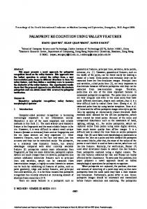
3) Finally, hand-based access systems work well in extreme weather and illumination conditions. One kind of hand-biometric technology is palmprint identification which is relatively new biometrics due to its stable characteristics [9]. There are several useful features in a palm image that can be categorized in the following groups: 1) Line features, like principal lines, wrinkles and ridges; 2) Geometric features, like size of the palms, angle between principal lines, etc. Line structure feature, which includes principal lines and wrinkles, is one of the most popular methods in palmprint recognition. Most palmprints show three principal lines: heart line, head line and life line. These lines are shown in Fig.1.
Index Terms—Palmprint, identification, wavelet and principal line.
I. I NTRODUCTION
T
HE great progress in the use of many applications in different areas, such as public security needs automatic personal identification. The traditional tools for obtaining personal ID are password and ID cards, which are widely used today. However, besides common problems with memorizing passwords and keeping an ID card, they are exposed to being disclosed or stolen, threatening the security. Today, the area of personal identification is exploiting computer-aided systems as a safer and more robust method and biometrics is one of the most reliable features that can be used in computer-aided personal recognition. Inconvenience with using the traditional methods caused a rapid increase in the application of biometrics. The commonplace biometric features are fingerprints [1], facial features [2], iris patterns [3],[4], speech patterns [5], hand geometry [6],[7], and palmprints [8]. Palmprints provide a number of privileges over other biometric features, making them an appropriate choice for identification applications: 1) First, they are more economical as palmprint images can be easily obtained using inexpensive CCD cameras. 2) Second, they are robust as hand features do not change significantly over time.
Fig. 1.
Principal lines of a plam
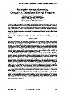
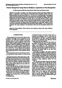
Although line structure features are very useful in palmprint recognition, systems that work based on these features face some problems: 1) In some cases principal lines and wrinkles are not enough to discriminate palms since there are many palms with similar line features. Fig.2 illustrates two palms with similar line pattern. 2) The lines (principal lines and major wrinkles) are difficult to be extracted because some palmprints are very unclear; samples for this kind of palmprints are shown in Fig.3. Because of these problems there is a lot of space for improving the online palmprint systems in the aspects of accuracy and capability of spoof attacks [10]. One useful way to overcome these problems and improve the accuracy of palmprint-
2
Fig. 2.
Two different palms with similar principal lines
wavelet is sensitive to differences between two images, so the second feature can detect the partial differences between palms which have similar patterns of principal lines (for example the difference in thin wrinkles). This method is explained in Section.II.B . Systems exploiting each of these features achieve high accuracy rates, but the overall accuracy can be further improved using a combination of the features in a ”hybrid system”. In Section.II.C we explained how to combine them in a proper way. Section.III reports some experimental results and Section.IV provides some conclusions. II. PALMPRINT
Fig. 3.
Palmprints with unclear principal lines
identification can be multispectral imaging [11],[12],[13], which captures an image in a variety of spectral bands (in palmprint recognition usually four spectral bands are used). Each spectral band highlights specific features of the palm and helps us collect more information to improve the accuracy of palmprint systems. So far, many approaches have been proposed for palmprint recognition. Kong [8] made a survey of this technique and divided the approaches into several different categories. There are some texture-based approaches (most of which used statistical methods for feature extraction), like Wavelet Transform (WT). Han [14] used a Wavelet-based Image Fusion method for palmprint recognition. There are also some line-based approaches. Palm lines including principal lines and wrinkles are very useful features of palmprint [8]. X. Wu [15] proposed some line features and used them for palmprint matching. Some other methods used ”Image coding” approaches. W. Jia [16] used Robust line orientation code for palmprint verification. Some other coding methods are used for palmprint recognition, such as Palm Code, Fusion Code, Competitive Code, Ordinal Code [17]. In the past decade, some appearance-based approaches were studied [18], And these approaches were also applied to biometrics including palmprint recognition. As discussed before, there are some problems in palm line extraction. The origin of these problems lies in the similarity of the principal lines, reducing discrimination capability between different palms. To overcome these problems we propose a hybrid feature that uses both principal lines and the weak lines. This hybrid feature is based on the following two features: 1) Principal lines and their energy in different locations of the palm. 2) Wavelet transform of palm image that can help us detect the small differences between different palms. The first feature is based on the principal lines and their energy in different locations of the palms. This feature can easily distinguish between palmprints with different principal lines, and is explained in Section.II.A . The second feature is based on Wavelet transform of the palm images. As we know
FEATURES
Multispectral methods require different samples of the same object in order to make a better decision. In this paper we assume that in image acquisition section four images of each palm sample are acquired using four CCDs. These images are then preprocessed and the Regions of Interest (ROI) for each of them are extracted. Provided these RIOs features are defined to represent each palm. Basically we employ two parallel classification paths, each working on its own set of features, and the final decision is concluded upon the results of the two paths. The two features used in this paper are palm-line power and wavelet power. The basic idea is to divide a palm image into a number of blocks and the power in these blocks is used as features. Suppose that the image is divided to J blocks of size M by N. The Power in the ij th block is defined to be:
P
(ij)
1 = MN
m=Mi X
n=N Xj
p(m, n)2
(1)
m=Mi−M+1 n=N j−N +1
Where p(m,n) is the value of palm image at point (m,n). A. Palm Line Extraction Palm of every hand includes lines and wrinkles that are exclusive to that hand. These lines are used in the palmprint identification literature for classification purposes, but the problem is that extracting a whole line is difficult. Many methods are proposed to extract lines, such as Canny edge detection method [19], designing masks to compute first and second order derivatives of palm images, thresholding palm images to form binary edge images and then applying Hough transform to extract the parameters of the six lines with highest densities[20], and some others. Here we do not aim to extract lines precisely, instead, we extract the region around each principal line and major wrinkle of the palm that contains the main characteristics of the palm. Line extraction process can be divided into the following steps: 1) Smooth palm image with a Gaussian filter; 2) Extract edges of the lines; 3) Compute second order derivative of the palm; 4) Mask the second order derivative image using the dilated version of the edge image; 5) Divide the resulting image into T×T non-overlapping blocks;
3
6) Compute power in each block and construct T×T feature vector. In the first step, palm image must be smoothed in order to reduce the effect of noise and to eliminate weak palm lines that do not capture our interest. The best method for smoothing images is applying a Gaussian filter to them. The discrete 2D Gaussian filter is defined to be: 2
2
(n−µ ) x) + 2σ2y ) −( (m−µ 1 2 2σx y (2) e 2πσ 2 Using linear filtering to apply this function to palm image, values of the Gaussian function are arranged in a matrix, called a mask. The result of applying this mask, G, to the original image, I, at point (m,n) can be computed using the following expression:
Fig. 5.
Edges of the palm
G(m, n) =
P (m, n) =
a b X X
M (s, t)I(m + s, n + t)
edges and a grayscale image of the second derivative values. Fig.6 depicts the result of this step. To combine these two
(3)
s=−a t=−b
The above filtering scheme has a number of parameters to be set; the Gaussian function has zero mean and a variance of 1 which was determined experimentally. Moreover, mask size, a and b, is another parameter to be set, here we used a square mask of size 7×7 (a=b=3), which was also experimentally chosen. Fig.4 depicts the smoothed image.
Fig. 4.
Fig. 6.
Second order derivative of palm
images, morphological dilation is used to expand the region around edges and then the two images are simply multiplied, resulting in an image containing major lines and wrinkles. In steps five and six, after these lines are extracted from images, each image is divided into a number of blocks and average energy in each of these blocks is computed. These numbers representing power of image in each of these blocks is then used as features. Extracting line features from each of the spectrums we get four vectors of features. Fig.7 represents the
Smoothed palm image
With the smoothed image available, edges of the principal lines must be extracted. Here, among many available different edge detection methods, Sobel was chosen. Although Canny edge detection method is very popular, it tends to connect otherwise separate pieces of lines resulting in a fully connected set of lines that do not demonstrate major features of the palm. Using Sobel provides the advantage that only edges of the major lines are detected and minor lines are discarded. After applying Sobel mask, there will also be isolated points that need to be eliminated. To remove them, a neighborhood approach was pursued: for every nonzero pixel consider a neighborhood of 3 by 3 pixels, if the number of adjacent nonzero pixels is less than 3 discard it. This post-processing demonstrates significant efficacy in discarding irrelevant isolated points. In the third step, second order derivative of the palm image is computed. Pixels with positive values are kept, since pixels of the palm at principal line locations have darker values than their surrounding pixels and usually second order derivative has its maximum values at these points. Fig.5 depicts the result of this step. In the forth step, palm lines are extracted from resulting images of the previous two steps: a binary image containing
Fig. 7.
combination of edge and second order derivative of palm
result of our line extraction method. As can be seen not all of the lines are extracted and for those that are extracted, the final lines are not necessarily connected. But these lines are actually enough, because they give the overall structure of the palm lines. After extracting the palm lines, we should find the palmline power features. As previously mentioned, there are 500
4
different palms in the database. Suppose that the palmsprints’ matrices are named from P1 to P500 . For each palm, there are 12 sample images in four spectrum bands (red, green, blue, NIR). Putting all of these twelve sample images in a row vector we get Pi , which can be written as: Pi = [ Pi1 |Pi2 | ... |Pi,12 ]
for
i = 1 : 500
(4)
Any of the Pij s consists of four images in four different spectrums. We represent the red, green, blue and NIR elements with Rij ,Gij ,Bij and Nij matrices. So Pij can be shown as: Pij = [Rij |Gij |Bij |Nij ]
(5)
Each of Rij , Gij , Bij , Nij is a 128 by 128 matrix, so Pij is a 128 by 512 matrix. After extracting palmlines, we divide each of Rij , Gij , Bij , Nij to 4 by 4 non-overlapping blocks. So each of these matrices is divided into 1024 sub-matrices. We number these sub-matrices from 1 to 1024 as it is shown in Fig.8.
Fig. 8.
matrix numbering
After that, we reform the Rij using the following equation: (1)
(1024)
(2)
Rij = [Rij , Rij , ..., Rij
]
(6)
(k)
Now, for each Rij the power of pixels’ illumination needs (k) to be computed. The power allocated to each Rij can be calculated using the following equation: X 1 (k) fij = p(m, n)2 (7) 16 f or all (k)
(m,n)∈ Rij
Where p(m,n) is the value of image at point (m,n). So the palmline feature vector for each Rij is a row vector with 1024 elements as shown below: (1)
(2)
(1024)
f(Rij ) = (fij , fij , ..., fij
)
(8)
Now, we have the feature vectors Rij . The feature of Gij ,Bij and Nij can also be extracted using the above method. The feature vector for each palmprint has 4048 elements as shown below: f(Pij ) = [ f(Rij ) |f(Gij ) | f(Bij ) |f(Nij ) ]
(9)
In the training section, we use 6 samples from each palmprint and find the feature vector of each of them, then the attributed feature vector to each palm can be found by averaging on these 6 feature vectors. For example, if we select the first 6 samples as training samples, we can find the feature vector for Pij using the following equation:
f(Pi ) =
P6
j=1 f(Pij )
(10) 6 To identify a sample Px , feature vector of the sample is extracted and then the euclidean distance of this vector to each of the 500 feature vectors in the palmprint data base is computed. We show the distance of Px from Pj with dL xj where L indicates the line feature. So : (L)
dxj = k f(Px ) − f(Pj ) k
(11)
(L)
dxj will be used in the final decision function. B. Discrete Wavelet Transform The Discrete Wavelet Transform (DWT) is used in a variety of signal processing applications, such as video compression [21], Internet communications compression [22] and object recognition [23]. Unlike the Fourier transform, whose basic functions are sinusoids, wavelet transform is based on small waves, called wavelets, of varying frequency and limited duration[24]. This transform is discrete in time and scale. In other words, the DWT coefficients may have real floating point values, but the time and scale values used to index these coefficients are integers. DWT can efficiently represent some signals, especially ones that have localized changes. Consider the example of representing a unit impulse function with the Fourier transform, which needs an infinite amount of terms because we are trying to represent a single quick change with sum of sinusoids. However, the wavelet transform can represent this short-term signal with only a few terms [24]. Although used in many fields, including mathematics, physics and image processing the terminology was different. In the late 1980s, Stephane Mallat unified the work into one topic, called Multiresolution Theory [25]. As the name implies Multiresolution theory is concerned with representation and analysis of signals in more than one resolution, based on the idea that some features may go undetected in one resolution while in another resolution they may be easily spotted. Multiresolution theory incorporates and unifies techniques from a variety of disciplines, including subband coding from signal processing, quadrature mirror filtering in digital speech recognition, and pyramidal image processing [26]. One powerful, but conceptually easy structure for representing images at more than one resolution is image pyramids, which is a collection of decreasing resolution images in the form of a pyramid. With the 1 by 1 image at the summit of the pyramid and the highest resolution image at the base of the pyramid, the image at the J-th level has a resolution of 2J by 2J. Normally P levels of the pyramid are used in processes. In image processing, wavelet transforms are used to create such pyramids. An image pyramid is shown in Fig.9. One dimensional DWT can be viewed as a pair of FIR filters, a lowpass filter and a highpass filter, each followed by a downsampler as depicted in fig.10. For the special case of Daubechies wavelets, these lowpass and highpass filters are FIR filters with 4 coefficients resulting in the following lowpass and highpass filters: LP F : h0 = az 0 + bz −1 + cz −2 + dz −3
5
Fig. 11.
Fig. 9.
Image Pyramid
HP F : h1 = dz 0 − cz −1 + bz −2 − az −3 Where, for example, for db2 the coefficients are a = 0.1294, b = 0.2241, c = 0.8365, and d = 0.4830. Here we used db1 which is equivalent to Haar wavelet with the following coefficients: d = 0, c = 0, b = a = 0.7071 = √12
One level of 2D wavelet transform using FIR filters
is computed. Using this scheme an overall of S*S features are extracted from each image. If J levels of decomposition is applied, each feature vector has a length of J*3*S*S, where 3 comes from the number of detail images[27]. Using Daubechies ’db1’ wavelet with 3 levels of decomposition for palm images from each of the four spectrums the method can be summarized in the following steps: 1) Decompose palm image to 3 levels using wavelet transform; 2) Divide each detail image into S×S non-overlapping blocks; 3) Compute power of each block and construct 3×3×S×S dimensional vector. In the training phase, 4 of such vectors are obtained for different spectrums of each palm image. These vectors are saved in the template. This template will then be used in the recognition phase to find the most similar palm to a given input. Fig.12 depicts a 3-level wavelet decomposition result.
Fig. 10.
A one dimensional wavelet transform
Applying discrete wavelet transform to images (or to 2D data) can be accomplished in one of the two ways; either by applying the low- and high-pass filters along rows of the data, then applying each of these filters along the columns of the previous results as depicted in fig.11 , or by applying four matrix convolutions, one for each lowpass/highpass, horizontal/vertical combination (i.e., low-horizontal low-vertical, lowhorizontal high-vertical, etc.). Xiang-Qian Wu proposed a method for wavelet-based feature extraction based on this property of wavelets that they preserve lines in horizontal, vertical and diagonal directions[27]. In this approach wavelet of the palm image is computed in a number of levels. They showed that three levels decomposition results in the best performance. Here, we use this method to extract features from our ROIs. Wavelet features are global features and do not describe spatial characteristics of the palm. In order to deal with this problem detail images are divided into S*S non-overlapping blocks and the power of each block
Fig. 12.
(a) palm image (b) 3-level wavelet decomposition
After computing the wavelet transform of the palmprints, features must be extracted. As for palm line features, first we form Pi and Pij using the equations (4) and (5). Therefore, we have the following equations : Pi = [ Pi1 |Pi2 | ... |Pi,12 ]
for
Pij = [Rij |Gij |Bij |Nij ]
i = 1 : 500
6
After that, the wavelet elements for all Rij , Gij , Bij and Nij must be found. For each of them there will be 9 wavelet elements which can be divided into 64 blocks. After calculating the average energy in each of these block we put them in a 64 by 9 matrix. Each column in this matrix is the blocks’ energy of one wavelet element. (9) (2) (1) For example for Rij we have wRij , wRij , ... , wRij , (k)
and each of the WRij is a column vector with 64 elements. (k)
(k)
′
Now for each wRij We transpose it and set all the wRij in a row vector and name it the wavelet feature vector of Rij and display it with wRij , so wRij is a row vector with 576 elements. ′ ′ ′ (9) (2) (1) (12) wRij = [ wRij |wRij | ... |wRij ] After extracting the wavelet feature of Rij , The feature of Gij ,Bij and Nij can be extracted in the same way. The feature vector of Pij can be extracted using the following equation : wPij = [ wRij |wGij | wBij |wNij ]
(13)
In the training section, we use 6 samples from each palmprint and find the feature vector of all of them, then the attributed wavelet feature vector to each palm can be found by averaging on these 6 wavelet feature vectors. For example, if we select the first 6 samples as training samples, feature vector for Pij can be extracted using the following equation : P6 j=1 wPij (14) w(Pi ) = 6 For test a sample like Px we can act like palm line feature section. First, we find it’s wavelet feature vector and after that we find its euclidean distance with wavelet feature vectors of all 500 palmprints. We show the distance between Px and Pj with dW xj where W represent the wavelet feature. So : (W )
dxj (W ) dxj
in the template is computed. After the two previous steps we W have two feature vectors dL xj and dxj . These features probably have different mean and variance, to make the decision fair we first normalize these distances. The normalized distance of palm lines and palm wavelets is computed using the following equation : (L) dxj (L) (16) dxj (normal) = (L) dx (ave) P500 (L) j=1 dxj (L) dx (ave) = 500 (W )
(W ) dxj (normal)
) d(W (ave) x
=
=
dxj (W )
dx
P500
j=1
(ave)
(17)
(W )
dxj
500 The winning class will be chosen upon the sum of these two normalized distances. So the decision function depends on both of these distances and can be defined as: (L)
(W )
DF (x, j) = dxj (normal) + dxj (normal)
(18)
For each Px the identified image will be Pk if k minimizes the above decision function. In other words x is k if and only if : o n (W ) (L) k = argminj=1:500 DF (x, j) = dxj (normal) + dxj (normal) (19) The averaging scheme has the advantage that it can moderate distortions that might occur in each individual spectrum and result in safer decisions. III. R ESULTS
= k w(Px ) − w(Pj ) k
(15)
will be used in the final decision function.
C. Identification Decision Function In our multispectral system, every time a person puts his hand on the palm sensor a set of images in four spectrums are taken: red, green, blue and infrared. To train the system for each individual, a number of these sets are required, four to six sets. Images in each of these sets are first passed to feature extraction sub-system resulting in eight feature vectors. In order to compensate for the effect of noise and misplacement of the palms, images of each spectrum are averaged over different sets and saved in the template. Now, to identify each new palm, feature vectors are first computed. Final decision is taken in three steps: 1) Compute average distance over four spectrums of the palm among palm line features. 2) Compute average distance over four spectrums of the palm among wavelet features. 3) Find the class with least over all distance. In the first and second steps, simply euclidean distance of the new palm feature vectors with those representing each class
Our palmprint identification algorithm is tested on a database [28] containing 6000 palmprints captured from 500 different palms. Every palm was sampled 12 times within different times. So there are 12 × 500 = 6000 groups of palmprint images. Every group contains 4 palm images collected at the same scene under 4 different illuminations, including Red, Green, Blue and NIR (Near Infra-Red).The resolution of these images is 128 × 128. Correct identification takes place when the palmprint is classified into a palm image whose label is same as the label of this palmprint and misidentification takes place when the palmprint is classified into a category whose label is different from the label of this palmprint. In our first experiment, half of the images from each group are used as training samples(in this experiment, the first six samples in each palm image are selected for training) and the remaining images are used as test samples. In all of the 3000 palmprints in the database, 14 samples were misidentified; So the identification accuracy is about 99.53%. To make the experiment fair, we design another test. For each palmprint we select six samples randomly as training samples and test on the other samples. We repeat this test ten times and compute the final accuracy rate by averaging on the accuracy rate of each experiment. So, the number of test
7
TABLE I ACCURACY RATE OF PROPOSED METHOD BASED ON NUMBER OF TRAINING SAMPLES ( THESE SAMPLES ARE SELECTED FROM 12 SAMPLES
Number of training samples 6 5 4
Number of test samples 30000 35000 40000
accuracy of Principal line method 94.58% 93.87% 93.22%
accuracy of Wavelet method 98.49% 98.25% 97.81%
accuracy of proposed method 98.88% 98.45% 98.08%
samples in this experiment is 30000. In this experiment an accuracy rate of about 98.8% is attained. Another experiment is done to examine the effect of training samples on the accuracy rate ( in all of these experiment we select the training samples randomly and repeat the test ten times). In the previous experiment, the number of training set samples and test samples for each palm were equal, in this experiment we reduce the number of the training samples to 5 and 4 and find out that the accuracy rate reduces a little, so this algorithm is robust to decline in the number of training samples. Therefore we can decide about a palmprint with less information. The result of this experiment is shown in Table.I. IV. C ONCLUSION This paper proposed a hybrid feature for palmprint recognition. This feature consists of two different features, which one of them is sensetinve to the major difference between different palms and the other one is sensetive to the partial difference between semilar palmprints. By using this hybrid feature, our algorithm is able to identify palmprints with similar line patterns and unclear palmprints. This algorithm calculates two normal distances for each palmprints which one of them is related two palmline energy and the other one is related to wavelet energy. These distances are combined in a decision function and the final decision is based on this decision function. The proposed algorithm has some advantages over previous method. First it has a high accuracy rate, second it is flexible to the number of traning samples and it is able to identify palmprints with a smaller number of training samples. In the future we will focus on the palmprints verification. This hybrid feature can be modified to be consistent with verification. V. ACKNOWLEDGMENTS The authors would like to thank The Hong Kong Polytechnic University(PolyU) for sharing their database(PolyU multispectral palmprint Database). R EFERENCES [1] Jain, L. Hong and R. Bolle, ”On-line fingerprint verification,” IEEE Trans. Pattern Analysis and Machine Intelligence, vol. 19, no. 4, pp. 302-313, 1997. [2] C. Liu and H. Wechsler, ”A shape- and texture-based enhanced Fisher classifier for face recognition,” IEEE Trans. Image Processing, vol. 10, pp. 598-608, Apr. 2001. [3] Daugman, J., ”High confidence recognition of persons by iris patterns,” IEEE 35th International Camahan Conference on Security Technology, pp. 254 -263, 2001. [4] R. P. Wildes, ”Iris recognition: An emerging biometric technology,” Proc. IEEE, vol. 85, pp. 1348-1363, Sept. 1997.
[5] W. Chou, ”Discriminant-function-based minimum recognition error rate pattern-recognition approach to speech recognition,” Proc. IEEE, vol. 88, pp. 1201-1223, Aug. 2000. [6] R. Sanchez-Reillo, C. Sanchez-Avila, and A. Gonzalez-Marcos, ”Biometric identification through hand geometry measurements,” IEEE Trans. Pattern Anal. Machine Intell., vol. 22, pp. 1168-1171, Oct. 2000. [7] R. Zunkel, ”Hand geometry based authentication,” in Biometrics: Personal Identification in Networked Society, A. Jain, R. Bolle, and S. Pankanti, Eds. Norwell, MA: Kluwer, 1999 [8] A. Kong, D. Zhang, and M. Kamel, ”A survey of pamprint recognition,” Pattern Recognition., 42(7):1408-1418, 2009. [9] D. Zhang, W. K. Kong, J. You, M. Wong, ”Online palmprint identification,” PAMI, vol. 25, no.9, pp. 1041-1050, 2003. [10] S. A. C. Schuckers, ”Spoofing and anti-spoofing measures,” Inf. Secur. Tech. Rep., vol. 7, no. 4, pp. 56-62, Dec. 2002. [11] R. Singh, M. Vatsa, and A. Noore, ”Hierarchical fusion of multispectral face images for improved recognition performance,” Inf. Fusion, vol. 9, no. 2, pp. 200-210, Apr. 2008. [12] R. K. Rowe, U. Uludag, M. Demirkus, S. Parthasaradhi, and A. K. Jain, ”A multispectral whole-hand biometric authentication system,” in Proc. Biometric Symp., Biometric Consortium Conf., Baltimore, MD, Sep. 2007, pp. 1-6. [13] Y. Hao, Z. Sun, T. Tan, and C. Ren, ”Multispectral palm image fusion for accurate contact-free palmprint recognition,” in Proc. Int. Conf. Image Process., 2008, pp. 281-284. [14] Dong Han, Zhenhua Guo, David Zhang, ”Multispectral Palmprint Recognition using Wavelet-based Image Fusion” ICSP2008 Proceedings [15] X. Wu, K. Wang, D. Zhang, Line feature extraction and matching in palmprint, in: Proceeding of the Second International Conference on Image and Graphics, 2002, pp. 583-590. [16] W. Jia, D.S. Huang, and D. Zhang, ”Palmprint verification based on robust line orientation code,” Pattern Recognition, 41(5):1504-1513, 2008. [17] F. Yue, W.M. Zuo, and D. Zhang, ”FCM-based orientation selection for competitive code-based palmprint recogniton,” Pattern Recognition, 42(11):2841-2849, 2009. [18] Z. H. Guo, D. Zhang, L. Zhang, and W. M. Zuo, ”Palmprint verification using binary orientation co-occurrence vector,” Pattern Recognition Letters, 30(13):1219-1227, 2009. [19] D. Tao, X. Li, X. Wu, and S. Maybank, ”General tensor discriminant analysis and gabor features for gait recognition,” IEEE Trans. Pattern. Anal. Mach. Intell, 29(10):1700-1715, 2007. [20] X. Wu, K. Wang, D. Zhang, Fuzzy direction element energy feature (FDEEF) based palmprint identification, in: Proceedings of International Conference on Pattern Recognition, vol. 1, 2002, pp. 9598. [21] J. Ozer, ”New Compression Codec Promises Rates Close to MPEG”, CD-ROM Professional, September 1995. [22] A. Hickman, J. Morris, C. L. S. Rupley, and D. Willmott, ”Web Acceleration”, PC Magazine, June 10, 1997. [23] W.W. Boles and Q. M. Tieng, ”Recognition of 2D Objects from the Wavelet Transform Zero-crossing Representation”, in Proceedings SPIE, Mathematical Imaging, (San Diego, California), pp. 104-114, July 11-16, 1993. Volume 2034. [24] M. Weeks, ”Digital Signal Processing Using MATLAB and Wavelets”, Infinity Science Press, Hingham, Massachusetts, 2007. [25] Stephane G. Mallat, ”A Theory for Multiresolution Signal Decomposition: The Wavelet Representation”,IEEE Transactions on Pattern Analysis and Machine Intelligence, VOL I I . NO. 7. JULY 1989 [26] Rafael C.Gonzalez and Richard E.Woods,”Digital Image Processing”,second edition, Prentice Hall [27] Xiang-Qian Wu, Kuan-Quan Wang and David Zhang,”Wavelet Based Palmprint Recognotion”,Proceedqs of the First International Conference on Machine Learning and Cybernetics, Beijing, 4-5 November 2002. ˜ [28] http://www.comp.polyu.edu.hk/biometrics/MultispectralPalmprint/MSP.htm