Proceedings of 3rd IEEE/IFIP International Workshop on Management of the Future Internet (ManFI), Dublin, Ireland, May 27, 2011
Network Virtualization in GpENI: Framework, Implementation & Integration Experience Ramkumar Cherukuri1 , Xuan Liu1 , Andy Bavier2 , James P.G. Sterbenz3 , and Deep Medhi1 of Missouri–Kansas City, USA 2 Princeton University, USA 3 The University of Kansas, USA {ramkumar.cherukuri, xuan.liu}@mail.umkc.edu,
[email protected],
[email protected],
[email protected] 1 University
Abstract—Great Plains Environment for Network Innovation (GpENI) is an international testbed for future Internet research. A key component of GpENI is programmable network virtualization (GpENI-VINI). The scope of this paper is to present the framework, implementation and integration experience with network virtualization in GpENI. In particular, this is described through our experience of implementing and integrating the XORP (eXtensible Open Router Platform) routing platform into GpENI-VINI. Preliminary results on measurements and validation are presented.
I. I NTRODUCTION GpENI (Great Plains Environment for Network Innovation) [6], [24] is an international testbed for future Internet research, initially consisting of The University of Kansas (KU), the University of Missouri–Kansas City (UMKC), Kansas State University (KSU), and the University of Nebraska-Lincoln (UNL) in the Midwest region of the United States. The project was initiated originally in response to the call for proposals under the NSF GENI program [5]. It has also been supported by funding and infrastructural support from the original four institutions with connectivity supports from the Great Plains Network, the Kansas Research and Education Network (KanREN) and the Missouri Research and Education Network (MOREnet). GpENI has been expanded to include a number of sites in Europe and Asia. An overview of GpENI is presented in [24] and a high-level topological connectivity is shown in Fig. 1. A major goal of the GpENI testbed is to provide programmable functionalities at three levels: at the end host level, at the network level, and at the optical level, along with an overall control framework. Along these core components, the lead effort was divided among the original partner institutions. The group at the University of Missouri–Kansas City led the effort for the network level functionality, i.e., network virtualization in GpENI. The scope of this paper is to present the framework, implementation and integration experience with network virtualization in GpENI. In particular, this is described through our experience of implementing and
Fig. 1.
GpENI Midwest Topology
integrating the XORP (eXtensible Open Router Platform) [18] routing platform into GpENI-VINI. GpENI network virtualization infrastructure (GpENI-VINI) provides network level resources such as virtual nodes and virtual links [20] for researchers. It allows researchers to create customized virtual networks, select preferable routing software, and select desired routing protocols to make this customized network topology into a testbed network. It allows researchers to inject networking events such as a link failure and a node failure. It also allows researchers to inject traffic through the customized virtual network. Creating a functional environment for network virtualization for researchers comes with a number of challenges. The first critical decision was whether to develop everything on our own or to use off-the-shelf components. We chose to consider porting network virtualization functionalities from VINI Veritas [20] that allowed us to satisfy the control framework requirements from GENI to be based on PlanetLab [13]. In doing so, we also added a number of new functionalities in the GpENI-VINI framework to provide further flexibilities to the researchers. A goal of this paper is to inform the research community of our experience so that this can serve as a lesson on how to build and manage a future Internet testbed. The rest of the paper is organized as follows. In Section II, we present an overview of the GpENI-VINI architecture. Virtual network resources and their enabling environment and challenges are described in Section III. XORP and its
1,3 Supported in part by NSF GENI program (GPO Contract No. 9500009441). 1 Supported in part by NSF Grant No. CNS-1029562. 2 Supported in part by NSF Grant No. MRI-0619434.
1
Database Server (PostgreSQL)
MyPLC
also modify the data of sites, users, nodes, or can add content to the GpENI-VINI Server. b) API Server is an interface between the database server (PostgreSQL) and other components of GpENI-VINI. MyPLC provides a few API methods to allow accessing data by using these methods. The API server listens on a port for incoming XML-RPC calls. Based on the incoming request method, first it authenticates the requestor, then it sends the request to the database server to get the data from the data base and returns the result to requested component. c) Database Server, based on PostgreSQL, is the primary storage space of GpENI-VINI resource data. Its function is to process the API server requests and send the results to the API server. d) Boot Server provides the required software for GpENI-VINI nodes. Software includes the boot OS and Node manager.
IIAS Tools
API Server XML-RPC
Researcher
Web Server
Boot Server
GpENI-VINI Central Server
HTTP/HTTPS HTTP/HTTPS
SSH
Sliver-1
Node Manager
Fig. 2.
Sliver-2
….
IIAS Tools GpENI-VINI N d Node
GpENI-VINI Architecture
implementation in GpENI-VINI is discussed in Section IV, while integration and automation are presented in Section V. Preliminary results on measurements and validation are presented in Section VI.
2) IIAS Tools: These tools are used to create a virtual infrastructure on the GpENI testbed. They assist researchers in selecting a virtual topology and in creating a virtual topology inside a slice. This includes a set of programs consisting of two parts: server side programs and client side programs. Server side programs create topology resource specifications of virtual links inside a slice based on users’ selection of topology. Once these topology resource specifications are created, they are stored in the GpENI-VINI database. Client (GpENI-VINI node) side programs are started by the node manager. These programs get the topology resource specifications from the database. Based on the topology resource specifications of a slice, these programs create virtual interfaces inside the sliver (virtual host context) and tunnel interfaces in the node (root context). By using tunnel interfaces, virtual links between slivers are constructed. Apart from the job of creating virtual and tunnel interfaces, these programs also provide support for Quagga [15] and XORP [18] to conduct routing studies. To support Quagga functionality on a virtual network, the IIAS tools write Quagga installation and Quagga routing configuration files for routing protocols such as RIP and OSPF into each slice file system. In the same manner, to support XORP on a virtual network, IIAS tools write XORP installation and XORP configuration files for a routing protocol into each slice’s file system (more details on XORP implementation in Section IV). These configuration and installation files can be used by researchers. 3) Trellis Node: Trellis [21] is a customized software system for nodes in the GpENI-VINI testbed. It is a combination of two virtualization technologies, Linux VServer [10] and NetNS [12], to support virtual nodes, virtual interfaces, and virtual links inside a node.
II. G P ENI-VINI A RCHITECTURE : A N OVERVIEW The GpENI-VINI framework requires familiarity with a number of terminologies such as slice and sliver; they are summarized in the Appendix. The core architecture of GpENIVINI, as currently available after our implementation and integration, is made of two parts: MyPLC [11] and IIAS (Internet In A Slice) tools [8]. Details on our implementation and integration will be presented in subsequent sections. MyPLC is portable PlanetLab central (PLC) software [11]; this acts as a VINI resource manager on the GpENI testbed. It manages all aspects of the testbed such as sites, resources (nodes), users, and slices. It has both a web interface and an API interface. The web interface facilitates easy access and management of user accounts. With the API interface, researchers can access data with a command line interface through XMLRPC. IIAS tools help researchers to create virtual interfaces and virtual links inside a slice. Fig. 2 gives an overview of the architecture on how different components of GpENI-VINI and researchers interact with the GpENI-VINI Central Server. There are several key Components of GpENI-VINI: 1) MyPLC: MyPLC [11] is portable PlanetLab software; by using this, we can create a private PlanetLab. It acts as the manager of GpENI-VINI resources. From a management point of view, it is a combination of four components: a web server, an API server, a database server, and a boot server. a) Web Server provides the web interface to researchers and the administrator. By using this interface, researchers [11] can create accounts, create slices, and select resources from the GpENI-VINI testbed. An administrator can enable, disable or delete users, sites, and nodes. An administrator can
2
GpENI-VINI node
4) Node Manager: Node Manager is a daemon on the node that manages the node. It polls the data from the server at regular intervals and makes changes according to that. Examples of changes include creating slivers and deleting slivers. It provides API for remote access and calls IIAS tools that are responsible for creating virtual interfaces and virtual links.
Sliver-1
Sliver-2
Application
Application
Kernel FIB
Kernel FIB
Vir if-1
Vir if-2
Vir if-3
….
Vir if-4
OS virtualization Layer
III. V IRTUAL N ETWORK R ESOURCES
Standard OS Layer
GpENI-VINI is responsible for the provisioning of virtual network resources that can be accessed through a slice interface. The virtual network resources inside a slice are available as long as the slice remains valid. By using virtual network resources we can build programmable virtual networks inside a slice. The virtual network consists of two components: virtual hosts and virtual links. The virtual networks resemble the real routable networks and provide a high degree of control to a researcher. The virtual network resources are built by using Trellis, a customized software system [21]. All GpENIVINI nodes run Trellis software, available from a GpENI-VINI server as a boot image. Details of the Trellis design can be found at [21].
Hardware
Fig. 3.
Trellis Design Architecture (adapted from [21]) GpENI-VINI Node-1
GpENI-VINI Node-2
Sliver-1
Sliver-2
Application
Application
Kernel FIB
Kernel FIB
Vir if-1
Vir if-2
Vir if-3
Sliver-1
Sliver-2
User p Space
Application
Application
Kernel Space
Kernel FIB
Kernel FIB
Vir if-4
Vir if-1
Vir if-2
Vir if-3
Researcher Tun if if-1 1
Tun if if-2 2
Tun if if-3 3
Vir if-4 Eth Packet
Eth Packet
Researcher Tun if if-4 4
Tun if if-1 1
Tun if if-2 2
Tun if if-3 3
Tun if if-44
IP H +GRE H + Eth Packet
A. Trellis Overview Originally, the Trellis [21] software platform was designed to support multiple programmable virtual networks on a single hardware system (a VINI node) and was designed to run on VINI nodes with the following properties: 1) Speed – Packets should be forwarded at high speed in the virtual network, 2) Isolation – It should provide isolation between virtual networks, i.e., one virtual network on one slice does not interfere with other virtual networks in different slices; it should provide isolation at the system level and the network level, 3) Flexibility – It should provide the flexibility to researchers to select their routing protocols (including any modification) in a virtual network environment, 4) Scalability – It should be able to simultaneously support a greater number of programmable virtual networks, 5) Low cost – Because it can run on a normal system, it should decrease the cost of hosting virtual networks. The Trellis [21] software system combines both host and network virtualization in a single system to meet the above listed desired properties. For host virtualization, Trellis uses a container based virtualization technology called the Linux VServer [10]. The main advantage of the Linux VServer is that it provides OS-level virtualization instead of full virtualization. It also gives acceptable speed and scalability with reasonable isolation and flexibility that are critically required properties. To provide network stack virtualization Trellis uses NetNS (Network Name Space) [12]. Network Name Space virtualizes all access to network resources from the root system to the container system. It gives network containers with its in-kernel virtual devices, IP table settings, FIB, and so on. Fig. 3 gives an illustration of Trellis architecture.
Fig. 4.
Virtual link between Slivers
B. Virtual Node Virtual nodes are built inside a GpENI-VINI node that runs Trellis software. It allows researchers to host multiple virtual networks on shared hardware (GpENI-VINI nodes). Trellis allows researchers to program their virtual topology based on their requirements such as a star, a mesh, or a fullyconnected network. It also allows the researchers to select routing protocols such as RIP, OSPF, or BGP and allows them to define their own forwarding tables. Besides Linux Vserver and NetNS, the Trellis system implements a new tunneling mechanism called EGRE (Ethernet over Generic Routing Encapsulation (GRE) [22] tunnel), that allows the node to support virtual hosts and virtual links. C. Virtual Link Virtual links give an illusion of a direct physical link between two systems, although they may be situated at multiple hops away. In GpENI-VINI, the virtual links are created between the slivers inside a slice. By using this virtual link analogy, we can build a virtual topology between nodes inside a slice. Fig. 4 illustrates a virtual link between slivers in a slice. D. Packet Flow in Virtual Link Once a virtual link is created, it is helpful to see the packet flow in it. In Fig. 4, the packets flow on a virtual link between
3
slivers inside a slice with an EGRE (Ethernet over GRE) tunneling mechanism. First, the data packet comes out of virtual interface that is an Ethernet frame in the context of a virtual host. This becomes the payload in the context of the root. At the tunnel interface (root context), this payload is encapsulated with a GRE header [22] and a four byte-key to demultiplex the packet to the correct tunnel interface. Then the IPv4 delivery header is added. The reverse process is carried out at the other end. First, the IPv4 header is removed, and then the GRE header is checked to determine the correct tunnel interface. Finally, the payload (Ethernet Frame) is delivered to the correct virtual interface of the sliver.
Resource Locators (XRLs) that are novel inter-process communication mechanisms to communicate with other processes. The lower-level subsystem can use traditional UNIX or Linux forwarding, the Click modular router [1], or Windows kernel forwarding. Currently, we use Linux kernel forwarding in the GpENI-VINI testbed. There are several different important XORP processes. For more details, refer to the XORP documentation [18]; they are summarized below: ∙ Forwarding Engine Abstraction (FEA) – This is a part of the lower-level subsystem. It communicates with higherlevel subsystems and forwarding paths. It provides an interface that is platform independent to support basic routing and network interface management functions such as set or get network interface information, and update forwarding table entries. In GpENI-VINI, we use kernel forwarding tables as forwarding engines. Thus, FEA writes forwarding entries into the kernel routing table. ∙ Routing Information Base (RIB) – It is a part of the higher-level subsystem. It contains a user-space copy of the entire routing/forwarding table. All the routing protocols communicate with RIB to update the routing entries and the RIB updates the FEA routing entries. ∙ Different Routing Protocols – The XORP router manager takes a configuration file as an input. This configuration file represents a list of interfaces and its control protocols and the type of forwarding engine abstraction; based on this, a corresponding routing protocol process is started. ∙ Router Manager – This is the first process that will start when a researcher runs XORP. This process is responsible for configuring and starting all components of the router. The configuration of the router can be changed through the router manager interface through CLI (Command Line Interface). ∙ Command Line Interface (CLI) – The XORP Shell (xorpsh) process implements CLI. The researcher is required to start this process to view the status and/or change the current configuration of the router. After making changes, the researcher is required to commit to get the changes affected.
E. Issues and Challenges While the current functionalities included routing capabilities through Quagga, we faced the following issues: ∙ Originally IIAS tools limited link creation to be between physically adjacent nodes as a design choice. While this made sense for the VINI Veritas testbed, we wanted to extend the functionality of the IIAS tools to allow arbitrary virtual topologies in GpENI-VINI. ∙ Routing tools such as XORP were not supported. Having such additional tools would allow researchers multiple programmable routing systems such as Quagga and XORP to choose from in their experimentation. ∙ There was no graphical user interface (GUI) to create a virtual network inside a slice. This limited researchers from a graphical view of the virtual network and they were required to use manual configuration through a file. To provide GpENI-VINI with additional services and make it user friendly to create a virtual network, our goal was to extend the functionality of the IIAS tools and design a prototype for the GUI. Thus, we faced the following challenges: 1) How to make a virtual network inside a slice to be a routable network allowing an arbitrary virtual topology, with the XORP routing application running (this is discussed in Section IV), 2) How to integrate an XORP routing application support with routing protocol (OSPF) in GpENI-VINI nodes (this is discussed in Section V), 3) How to run/start a routing application inside all slivers of a slice simultaneously (this is discussed in Section V).
B. Routing Implementation Before incorporating XORP on the GpENI-VINI testbed, we first tested it on one of our internal lab demo platforms. Initially, we downloaded XORP version 1.6 from [18]. We configured and tested XORP for its routing functionality by using the OSPF routing protocol. We created two virtual interfaces on the Ethernet interface and configured those with OSPF and then tested them. After compilation of XORP 1.6, we found that this occupied around 2.2 GB of disk space, where the XORP directory contains configuration, make, different routing protocol daemons, documents, and other related files. Next, to implement XORP in the GpENI-VINI testbed, we needed to create a slice with a virtual topology. We created a virtual topology (see Section V) inside a slice called
IV. XORP I NTEGRATION IN G P ENI-VINI A. XORP: Overview XORP [18] supports IPv4 and IPv6 routing protocols such as RIP, OSPF, BGP, and PIM-SM. It supports unicast routing policies and SNMP. The architecture of XORP [18] consists of two subsystems. The first one is at a higher-level (“userspace”) that consists of the routing protocols and management mechanisms. The second one is at a lower-level (“kernel”) that provides a forwarding path and API for the higher-level to access. XORP uses a multi-process architecture at the user-level with one process per routing protocol. It also uses XORP
4
Researcher
GpENI-VINI node
Sliver-1
Sliver-2
Application
XORP
Kernell K FIB
Kernell K FIB
Vir if-1
Vir if-2
Vir if-3
∙
SSH
… .
Vir if-4
OS virtualization Layer
Standard OS Layer
Hardware
GpENI Testbed
Fig. 5.
XORP on a Sliver
“umkc test1” with three nodes. With XORP 1.6 requiring approximately 2.2 GB for each node, this needed to be replicated in every sliver in a slice by building and installing XORP. This turned out to be a time consuming process requiring approximately 30 minutes to configure and build. Thus, we realized that XORP 1.6 was not a scalable option for the end users due to such a large setup time. As we debated how to proceed next, especially to scale down the setup time, a parallel event occurred. XORP Inc (ICSI Berkeley, CA) decided to sell XORP assets [17]. After a month or so, XORP’s new version 1.7 was made available as XORP.CT-1.7 under Candela Technologies [19] through a GNU General Public License based on the official version of XORP 1.7 SVN repository. We decided to try XORP implementation with this new version on our test slice (umkc test1). By using the new version, the biggest advantage that we observed was that it created an executable binary file in compressed form after building XORP. This was advantageous to us in building the XORP latest version on the GpENI-VINI Server and put in our GpENI-VINI local software repository, so that it can be distributed as an executable binary file to the nodes whenever a researcher requests it for an experiment. This was found to be useful for GpENI-VINI nodes as this significantly saves configuration time and memory space.
∙
messages of rtrmgr, we circumvented the situation by explicitly specifying the log file and telling the rtrmgr process to save the entire log onto this file. Failed to start router manager (rtrmgr) – The router manager process takes a configuration file as input to configure different interfaces and start different routing protocols. When we initially tried to start the router manager process with the configuration file, it failed to start. At first, we had difficulty identifying the cause for this problem. We tried a number of options to remedy the situation. Finally, we used the strace (System Trace) debugging utility in Linux to find the error. We ran the router manager process on a normal lab machine and in a sliver of a slice. We started the router manager process with strace and saved all the system calls in a file. After careful analysis and comparison of both files, we found that there is an error in configuration of interfaces. The issue that caused the trouble was that in the XORP configuration of interfaces, it takes both the physical interface and the virtual interface that is related to that physical interface. On the other hand, only the virtual interface was declared initially, because there was no physical interface in a sliver. We resolved this problem by giving both interface values as virtual interface values. Thus, we created a new configuration file that reflected this. Cannot enter into XORP configuration mode – We ran the xorpsh process to view the status or update configuration of the router application through CLI. If this is successful, one can enter into a default mode (view mode). There are two modes in CLI access. The first mode is a view where we can see the status of the router. If we want to change the current configuration, we needed to enter into the second mode called the configure mode by typing “configure” at the command prompt when we are still in view mode. When we typed “configure” in the view mode, we received the error message, “you do not have permission to enter into configure mode.” We finally realized that we added the current user to the XORP group after starting the router manager process. We solved this issue by killing the router manager process and restarting it again. Upon successfully implementing this, we were able to enter into the configure mode.
V. I NTEGRATION AND AUTOMATION IN G P ENI We have made three specific contributions towards integration and automation in GpENI: 1) Viewing virtual topologies using a GUI, 2) Extending topology creation to relax restrictions on virtual links, and 3) Automatically generating XORP configuration files that are customized for the virtual topology. In this section, we present technical details on how these have been accomplished.
C. Issues and Experience Working with XORP Implementing XORP has created its own challenges. This required immense understanding of the underlying architecture of both XORP and Trellis. Here we summarize a few key issues we faced while implementing XORP-1.7 on a sliver of a slice (”umkc test1”) in the GpENI-VINI testbed. ∙ Failure of error message generation – When we ran the router manager (rtrmgr) process, it could not display the status/error messages to the console; instead, it simply went back to the console. We thought there was a problem with the standard I/O system. To see the status or error
A. IIAS Tool Features Before getting into details of extended functionalities of IIAS tools on GpENI-VINI testbed, let’s first recall several
5
features of the original IIAS tools. IIAS tools are based on VINI-Veritas [16] and were written in python. On the server side, two software components, topology and create-topo-attributes, are referred to as the Topology Resource Specifications (“topo rspec”) generator. The topology module contains the list of physical links between adjacent sites in the GpENI-VINI testbed. These adjacencies must be manually added by the GpENI-VINI administrators, a laborious process. Running as a cron job (currently, the default is set to every 15 minutes), create-topo-attributes takes the list of physical links information contained in module topology as input to generate virtual topology links in the slice, if the slice tag “topo links” is set as “iias”. In other words, the functions of create-topo-attributes will create topology resource specifications (“topo rspec”), hosts and virtual topology links. The topology resource specifications (“topo rspec”) originally represent only unidirectional links. The IIAS tools create “topo rspec” in the following formats: “node-id”, “IP address”, “Link rate”, “my virtual tip IP”, “remote virtual tip IP”, “virtual network.” On the client side, IIAS tools contain two python modules: optin and topo; these together are called the topology manager. They can be accessed in the root context of the GpENI-VINI node. This is done by extending the original node manager from the PlanetLab with plug-ins. Optin generates open VPN configuration files that support the injection of external traffic into the virtual network topology. The node manager polls the latest sliver information every 15 minutes from the GpENI-VINI server and passes a copy of this to topo. The topo program interprets the “topo rspec” attribute values and performs the following basic functions: 1) Creates virtual and tunnel interface names based on the EGRE key and node ids, 2) Creates new and clears old virtual interfaces based on topo rspecs, 3) Creates new and clears old tunnel interfaces based on topo rspecs, 4) Creates and deletes NAT interfaces in both the root context and the sliver context, 5) Sets up and tears down EGRE links and NAT.
Sliver-1
Sliver-2
Quagga Configuration
Quagga Configuration
XORP Quagga Installation And XORP Configuration files
XORP Quagga Installation And XORP Configuration files
Node Manager
Fig. 6.
GpENI-VINI Node
….
IIAS Tools
GpENI-VINI node with extended IIAS tools
be written into gui_topo module together with the relevant slice’s name. Then the extended IIAS software component gui-create-topo-attributes will import information of both slice name and topo links from gui_topo and generate topology resources specification (“topo rspec”). It will create a “topo links” tag value, which represents all the links in a virtual topology network. For example, if node A has id 1 and node B has id 2, “topo links” consists of the value [(1, 2), (2, 1)], where each one represents a unidirectional link. D. Integrating XORP to IIAS Tools on Client Side On top of these basic functions, we have now added the XORP supporting functionality to create the XORP configuration file based on sliver interfaces and to write this configuration in the corresponding sliver file system. We have also extended the IIAS functionality to automate the routing process in virtual network topologies on GpENIVINI resources. This is helpful to researchers by making it easy to use XORP for their experimentation. To automate the routing process, we have also added the following features to the IIAS tools: 1) Created the XORP installation and startup programs, 2) Created the code experiment that takes user choices such as credentials, slice name, routing software, version, and protocol. This triggers routing daemons in all the slivers of a slice at a time with the help of codeploy [2]. We have also added an XORP installation and Quagga installation program to the IIAS tools. To make the routing processes automated, we have created XORP and Quagga local repository files at the GpENI-VINI server. Hence, these installation programs point the GpENI-VINI server to get XORP and Quagga software. The experiment code is now made available from the GpENI-VINI server [7] so that researchers can readily download and use it for their experimental work. Fig. 6 shows what the extended IIAS tools and the automation tool of the GpENI-VINI node contain. Finally, the integration component is useful to researchers to run routing applications with a XORP configuration file on each sliver of a slice. This removes the burden from
B. Web-based GUI Design We have created a web-based GUI to create and view virtual topology in a user’s slice. With the GUI, a list of nodes within the slice will be shown, together with their node ids. Meanwhile, we can view the current virtual topology link information in the form of [(𝑎, 𝑏), (𝑏, 𝑐), ..., (𝑚, 𝑛)], where the letters represent the node ids of nodes in the slice. To create the topology, the user can just enter the topo links information in the same format. C. Extended Features of IIAS Tools on Server Side Based on the original IIAS tools, we have extended its features to support a virtual topology creation through a GUI. To support the GUI functionality, we have modified the IIAS tools on the server side. When the user has confirmed the topology creation, the topo link information will
6
TABLE I RUN T IME OF XORP I NTEGRATION # Links 1 2 3 4 5
Average (ms) 430.0 443.4 476.4 486.6 490.4
TABLE II RUN T IME OF ROUTING AUTOMATION
StdDev 8.631 8.792 7.369 11.059 16.935
# Nodes 3 4 5 6
researchers to write the configuration information for each and every interface and protocol. For example, if a researcher has an 𝑁 -node fully connected network in his/her slice for a project, he/she would need to write 𝑁 different configuration files each with 𝑁 − 1 interfaces; this can be time consuming. Our integration tool has automated this phase.
Average (s) 204.6 468.0 890.0 1034.2
StdDev 22.075 37.543 39.592 69.941
GpENI-VINI Testbed 1
192.168.20.64/30
2
192.168.32.168/30
192.168.20.168/30
VI. P RELIMINARY M EASUREMENTS AND VALIDATION
3
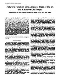
We report measurement time taken using two XORP programs that are integrated into the node side of IIAS tools. These two programs generate an XORP configuration file for the OSPF routing protocol and an XORP installation script for the automation process. To measure time taken by these programs, we added time functionality in IIAS tools. We also created different numbers of virtual links inside a sliver and measured the run time. Table I shows the average time and the standard deviation over five different instances with different numbers of virtual links that captures the integration time taken to create XORP installation script and to create OSPF configuration file inside the slice file system. This measurement does not include any network connection delays. We observe that with the addition of virtual links, it takes additional time to generate header configuration and forwarding configuration information. The increase in time appears to be linear in nature in terms of the number of virtual links. We have also created a routing study automation program to make it easy to start a routing application simultaneously without logging onto each sliver. The researcher can use this program from her laptop to start the routing application on each sliver of the slice with their SSH key. To measure the total run time of this application, we considered slices with a different number of nodes. Table II shows the average time and the standard deviation to start the XORP routing application on each slice measured over five instances; this measurement is based on when the user initiates the routing automation from her laptop using the automation script. The variation can be attributed to the number of slivers (virtual nodes), the network condition such as link speeds, and the physical location of slivers from the GpENI-VINI server since slivers need to download the XORP software from the server. Our sample nodes were located in physically diverse regions. We took four nodes from the Midwest region of the USA and two additional nodes from the European region. Results up to four nodes are based on the fours nodes in the Midwest region; with these nodes the average automation time is less because of physical proximity. Results beyond the four
192.168.36.168/30
4
umkc_test-11 1: router-1.ksu.GpENI.net 2: router-1.unl.GpENI.net 3: router-1.simula-no.GpENI.net 4: router-1.umkc.GpENI.net
Fig. 7. Slice used in experiment (node failure: node 3; link failure: link 2-3)
nodes and up to six nodes include the nodes added from the European region; this increases average automation time due to the physical distance between the regions. In addition to the above measurements, we used the experiment code to validate the workings of an XORP routing application inside a virtual network with the OSPF protocol. To validate, we have injected two networking events called Node Failure and Link Failure in a Virtual Network. Assume that a slice “umkc test-11” consists of four nodes (router-1.ksu.geni.net, router-1.unl.geni.net, router-1.simulano.geni.net, and router-1.umkc.geni.net) from the GpENIVINI testbed environment. Inside this slice, we have created a virtual network as shown in Fig. 7 and started an XORP routing process with an OSPF configuration on all interfaces in all slivers of this slice. Before the node failure event, we verified the routing tables of router-1.ksu.gpeni.net and router-1.unl.gpeni.net to ensure that the tables were consistent. We then injected a node failure by killing the XORP process on router-1.simula-no.gpeni.net sliver (virtual node #3). This node failure event caused one network’s entry in the routing table to be removed and isolated the virtual network into two networks. We found the resulting routing tables to be consistent. We also tested the link failure on another slice “umkc test12” with the same four nodes. In this slice, we injected a link failure by breaking the link between router-1.unl.gpeni.net and router-1.simula-no.gpeni.net, i.e., between virtual nodes 2 and 3 (see Fig. 7). Again, routing table consistency was observed after checking the routing table.
7
VII. R ELATED W ORK
we needed to identify that a new slice tag is needed and what modifications needed to be made to the code base that would allow creating this tag. Our efforts strongly benefited from regular communication between the groups at UMKC and Princeton University where the VINI Veritas was developed. Currently, GpENI-VINI has over 30 nodes located in geographically diverse regions, and we continue to add GpENIVINI nodes as institutions join to become partners of the GpENI testbed. Courseware has also been recently designed on how to use GpENI-VINI and we plan to make it available to the research community. A large-scale experimentation is also planned in the near future. R EFERENCES
There has been several future Internet initiatives worldwide such as NSF-GENI program [5], EU FP7 FIRE programme [4], and Japanese JGN2Plus [9]. There are a number of networking testbed environments that provide distributed networking and system resources with required services and tools. PlanetLab [13] is one of the largest networking testbeds that has a worldwide presence. This allows researchers to select resources from across the world to evaluate their experiments. VINI Veritas [16], [20] uses PlanetLab framework and provides the programmable networking resources; our implementation builds on this work. Emulab [3] is also one of the large scale networking testbeds with a worldwide infrastructure. This facilitates the researchers to select group nodes for their experiment and researchers can run whatever application they want. ProtoGENI [14] is a control framework that is developed by using Emulab and PlanetLab. This framework facilitates the allocation of resources from diverse components including distributed systems, programmable hardware (NetFPGA) systems, and wireless network devices. CoreLab [23] is a recent testbed effort that employs the hosted virtual machine monitor concept. A key difference between GpENI and other testbed efforts is that GpENI encompasses a programmable framework at three levels connected through a control framework. As part of the overall framework, GpENI-VINI focuses on the programmable network virtualization component.
[1] [2] [3] [4] [5] [6] [7] [8] [9] [10] [11] [12] [13] [14] [15] [16] [17]
VIII. S UMMARY
[18] [19] [20]
In this paper, we report on our experience with GpENIVINI, the programming network virtualization component in GpENI. This platform is developed by using major components from the VINI Veritas framework. In doing so, we found that there were a number of functionalities that we wanted to have in GpENI-VINI that were not readily available in VINI Veritas. In particular, a significant part of our effort went to the development a functional XORP routing capability and to automate the process of making virtual network as real routing networks by using XORP/Quagga routing demons/application/software in GpENI-VINI. This exploration led to our findings on limitation of using XORP version 1.6 in a programmable network environment. Instead, we used XORP version 1.7 that provided the needed flexibility for GpENI-VINI. Secondly, XORP integration and automation in GpENI-VINI also came with its own challenges. There are a number of important lessons we learned from our efforts in this project. A key part is that network virtualization requires a strong understanding of the separation between interfaces that are virtual and physical and how they interact, including how to troubleshoot. Secondly, to be able to allow researchers to create a dynamic topology for their experimental work, we needed to understand existing capabilities of IIAS tools and what types of extensions required in this toolset. Thirdly, to be able to provide a GUI to view a virtual network,
[21]
[22] [23] [24]
“Click modular router.” http://read.cs.ucla.edu/click/click “Codeploy.” http://codeen.cs.princeton.edu/codeploy/ “Emulab.” http://www.emulab.net/ “FIRE – Future Internet Research & Experimentation: European Commission ICT research in FP7.” http://cordis.europa.eu/fp7/ict/fire/ “GENI – Global Environment for Network Innovations.” http: //www.GENI.net “GpENI – Great Plains Environment for Network Innovation.” http://www.GpENI.net “GpENI-VINI home.” http://geni-myvini.umkc.gpeni.net/ “IIAS tools.” http://svn.planet-lab.org/wiki/ViniInternetInASlice “JGN2Plus: NICT initiative.” http://www.jgn.nict.go.jp/ “Linux-VServer.” http://linux-vserver.org/ “MyPLC user guide.” https://svn.planet-lab.org/wiki/MyPLCUserGuide “NetNS.” https://lists.linux-foundation.org/pipermail/containers/ 2007-September/007290.html “PlanetLab.” http://www.planet-lab.org/ “ProtoGENI.” http://www.protogeni.net/ “Quagga routing software.” http://www.quagga.net/ “VINI Veritas.” http://www.vini-veritas.net/ “XORP assets selling notice.” http://mailman.icsi.berkeley.edu/ pipermail/xorp-announce/2010/000011.html “XORP open source routing software.” http://www.xorp.org/ “XORP.CT branch.” http://www.candelatech.com/xorp.ct/ A. Bavier, N. Feamster, M. Huang, L. Peterson, and J. Rexford, “In VINI Veritas: Realistic and controlled network experimentation,” in Proc. ACM SIGCOMM 2006, September 2006. S. Bhatia, M. Motiwala, W. M¨uhlbauer, Y. Mundada, V. Valancius, A. Bavier, N. Feamster, L. Peterson, and J. Rexford, “Trellis: a platform for building flexible, fast virtual networks on commodity hardware,” in Proc. 2008 ACM CoNEXT Conf., Madrid, Spain, 2008, pp. 72:1–72:6. D. Farinacci, T. Li, S. Hanks, D. Meyer, and P. Traina, “Generic routing encapsulation (GRE),” IETF RFC 2784, March 2000. A. Nakao, R. Ozaki, and Y. Nishida, “CoreLab: an emerging network testbed employing hosted virtual machine monitor,” in Proc. of 2008 ACM CoNEXT Conf., Madrid, Spain, 2008, pp. 73:1–73:6. J. Sterbenz, D. Medhi, B. Ramamurthy, C. Scoglio, D. Hutchison, B. Plattner, T. Anjali, A. Scott, C. Buffington, G. Monaco, D. Gruenbacher, R. McMullen, J. Rohrer, J. Sherrell, P. Angu, R. Cherukuri, H. Qian, and N. Tare, “The Great Plains Environment for Network Innovation (GpENI): A programmable testbed for future Internet architecture research,” in Proc. of 6th International Conference on Testbeds and Research Infrastructures for the Development of Networks & Communities (TridentCom), Berlin, Germany, May 2010, pp. 428–441.
A PPENDIX : G LOSSARY Node: Any dedicated physical system that runs PlanetLab and VINI components in the GpENI testbed. Site: Any geographical location (ex: a University or an Organization) where GpENI nodes are located. Slice: It is a group of resources (nodes) allocated from distributed nodes across the GpENI testbed to a project. Each slice has a finite lifetime and must be renewed before it expires. Sliver: Sliver is a slice running on a specific node. It is a virtual host on a node that is participating in the slice. A sliver (virtual host) is created with the slice name on participating nodes.
8