consists of an AC-DC power converter with its DC output connected to a pair of ...... to 3700 K while the outer lane consists of a total of 8 cool- white LEDs with a ...
Non-Linear Feedback Control of Robust Bi-Color LED Lighting Albert T.L. Lee1, Huanting Chen1, Siew-Chong Tan1, S.Y. (Ron) Hui1,2 1
Department of Electrical & Electronic Engineering, The University of Hong Kong, Hong Kong, China 2 Department of Electrical & Electronic Engineering, Imperial College, London, U.K.
Abstract—Light-emitting diode (LED) technology involves highly complex interactions of heat, light, power and color. Dimming a bi-color LED system with color mixing feature will alter the power and junction temperatures, which in turn shift the color spectra of the LEDs. In this paper, a closed-loop control method based on the nonlinear empirical LED model is proposed for decoupling the dimming control and color control of a bi-color system comprising warm-white and coolwhite LEDs. The proposed control scheme has been successfully implemented to provide highly precise and independent control of dimming and correlated color temperature (CCT). Even considering significant changes in ambient temperature, the maximum errors in luminous flux and CCT employing the proposed method are around 3% and 1.78% respectively while the corresponding errors using an existing linear duty-cycle control method are 20% and 27.5% respectively.
another parallel string of cool-white LEDs. The system architecture of the proposed bi-color LED lamp will be introduced. This is followed by a presentation of the theory of the proposed nonlinear feedback control scheme. The proposed control methodology is formulated using the nonlinear empirical LED model recently reported in [5], which takes into consideration the thermal coupling effect of the two color sources and the actual imperfections of the LED. The actual implementation of the proposed bi-color nonlinear controlled LED lamp will be presented. Finally, experimental measurements are included to demonstrate the highly precise control of the light intensity and the CCT. Such measurements are compared with those obtained from an existing color mixing method based on linear duty cycle control. In addition, the proposed LED system is shown to be robust to ambient temperature changes even without the use of a temperature sensor.
Index Terms—Non-linear feedback control; luminous flux; correlated color temperature (CCT); light-emitting diodes (LED).
II. SYSTEM ARCHITECTURE
I. INTRODUCTION Dimmable bi-color LED lamps with adjustable light intensity and correlated color temperature (CCT) are emerging products in the general lighting market. Bi-color LED systems based on the color mixing of warm-white and cool-white LEDs offer both dimming and color-mixing features. LED drivers suitable for multiple strings and color control have been previously addressed [1]-[4]. LED systems involve complex interactions of power, heat, light and color. As an example, a change in the LED power causes a corresponding change of light intensity and junction temperature which, in turn, leads to a shift of color spectra of the LEDs. Nonetheless, conventional linear control adopted in existing bi-color LED lighting products assumes that the nominal color temperatures of the warm-white and cool-white LEDs remain constant. It employs simple duty cycle control to perform color mixing. Obviously, such assumption fails to account for the temperature dependent changes of light intensity and color temperature of the LED which is the primary reason of existing bi-color LED products’ inability to provide precise dimming and color control. In this paper, a closed-loop nonlinear control scheme that can achieve precise and independent dimming and CCT control for a color-mixing LED system is reported. The colormixing system consists of a string of warm-white LEDs and
978-1-4673-7151-3/15/$31.00 ©2015 IEEE
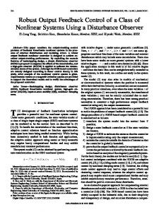
Fig. 1. Functional block diagram of the proposed bi-color LED lamp.
Fig. 1 shows the functional block diagram of the proposed bi-color LED lamp. Unlike its predecessor with open-loop control [5], a low-cost RGB color sensor is employed in the proposed closed-loop system to enable real-time feedback of CCT and luminous flux values of the combined light mixture from the two LED sources. The color sensor enables red, green, blue and clear (RGBC) light sensing for precise measurement of CCT and flux values which are fed back to the microprocessor. The power stage of the bi-color LED system consists of an AC-DC power converter with its DC output connected to a pair of current-controlled DC-DC buck converters (or LED drivers). The AC-DC power converter converts a universal AC line input voltage to a DC voltage of 48 V. One of the two DC-DC buck converters drives the warm-
3215
white LED string while the other drives the cool-white LED string. The microcontroller (MCU) generates two distinct pulse-width modulated (PWM) signals with a certain set of duty ratios (Dw, Dc) to achieve independent dimming and color control of the two LED strings. A calibrated color sensor is mounted on the LED printed circuit board which is used to periodically measure the combined flux and CCT from the two strings. The actual values of flux and CCT are fed back to the MCU for comparison with the corresponding target values of flux and CCT. By applying a dedicated software algorithm, the MCU determines a new set of duty ratios for driving the two LED strings in such a way that the actual flux and CCT values continue to track closely with the corresponding target values despite any changes in the operating condition. The underlying operating principle of the proposed bi-color LED lamp will be discussed in the next section.
is found at Dφ = 0 and φm = 300 lm which is unacceptably large. In addition, it has been shown that CCTm does not vary linearly with Dφ as predicted by the linear model [5]. Hence, this leads to the motivation in developing a non-linear empirical LED model to achieve precise dimming and CCT control performance. From the definition of colorimetry, the chromaticity (x,y,z) of a light source can be expressed in terms of the tristimulus values (X,Y,Z) as follows [5].
X °x = X + Y + Z ° Y ° ®y = X +Y + Z ° Z ° °z = X + Y + Z ¯
III. THEORETICAL CONSIDERATION Nonlinear empirical flux and CCT model of the LEDs, which considers the thermal coupling effect of two distinct color sources and the actual imperfections of the LEDs, is proposed in [5]. It entails the motivation and fundamental theory of developing such an LED model which is important to realizing a high-quality bi-color LED product. This section begins with a quick review of the nonlinear LED model. Building upon that, the operating principle of the proposed nonlinear feedback control scheme of a bi-color LED system will then be discussed in detail. A. Review of the Nonlinear Empirical LED Model The LED system under consideration is a bi-color white LED system comprising two distinct LED strings of two different nominal CCT values. It includes a controller which enables the adjustment of the overall light intensity (luminous flux) and CCT by varying the PWM duty ratio in each of the two different-colored LED strings. For the conventional linear approach, the control of flux and CCT in a bi-color LED lamp is governed by the following mathematical expressions [5]. φm = φw + φc ° φw φc ® °CCTm = CCTw Dφ + CCTc (1 − Dφ ) = CCTw φ + φ + CCTc φ + φ w c w c ¯
Let (Xw,Yw,Zw) and (Xc,Yc,Zc) be the tristimulus values for the warm-white and cool-white LED sources, respectively. The overall tristimulus values (Xm,Ym,Zm) of the effective light mixture from both sources in a bi-color LED lamp is the sum of the respective sources, i.e.,
Xm = Xw + Xc ° ®Ym = Yw + Yc °Z = Z + Z w c ¯ m
(3)
Hence, from (2) and (3), the overall chromaticity coordinates (xm,ym,zm) of the bi-color LED system are given by
xm =
ym =
(1)
zm =
where φm and CCTm represent the total flux and CCT, respectively, of the combined light mixture from the warmwhite and cool-white LEDs in the bi-color lamp. φw and φc are the luminous flux value of the warm-white and cool-white LEDs, respectively. CCTw and CCTc are the CCT values for the warm-white and cool-white LEDs, respectively. Dφ is the ratio of the averaged emitted warm color light flux φw over the total light flux of the lamp (φw + φc), i.e. Dφ = φw / (φw + φc). The linear control method assumes that the values of CCTw and CCTc are constant. Also, the combined CCT (CCTm) is assumed to change linearly with the flux ratio Dφ. It has previously been verified that by employing such a linear model, the measured CCT differs significantly from the theoretical CCT [5]. In fact, a maximum CCT error of 1400 K
(2)
Xw + Xc Xw Xc + xw xc Yw + Yc Yw Yc + yw yc Z w + Zc Zw Zc + z w zc
(4.1)
(4.2)
(4.3)
Since the tristimulus value Y, which represents luminance, is proportional to the luminous flux φ, and the chromaticity y can be approximated as being proportional to CCT. Equation (4.2) can be re-expressed as
CCTm =
φw (Dw , Dc ) + φc (Dw , Dc ) φw (Dw , Dc ) φc (Dw , Dc )
(5)
+ CCTw,avg ( DT ) CCTc,avg (DT )
where Dw and Dc are the duty ratios for the warm-white and cool-white LEDs (i.e. 0 Dw 1, 0 Dc 1) and the total duty ratio DT is the sum of Dw and Dc, i.e. 0 ≤ DT = Dw + Dc ≤ 2. For a particular DT, the average CCT values for the warm-white and cool-white LED, i.e. CCTw,avg, and CCTc,avg, are given by
3216
CCTw,max − CCTw,min ( DT − DT ,min ) + CCTw,min °CCTw, avg (DT ) = DT ,max − DT ,min ° (6) ® °CCT (D ) = CCTc,max − CCTc,min D − D ( T T ,min ) + CCTc,min c , avg T ° DT ,max − DT ,min ¯ where CCTw,max and CCTw,min are the maximum and minimum CCT values of the warm-white LED, respectively. CCTc,max and CCTc,min are the maximum and minimum CCT values of the cool-white LED, respectively. The maximum and minimum CCT values of the warm-white (or cool-white) LED are measured as a function of the total duty ratio DT [5]. DT,max represents the maximum total duty ratio which produces the maximum CCT whereas DT,min represents the minimum total duty ratio which corresponds to the minimum CCT. Equation (5) defines the overall CCT of the combined light mixture which is a nonlinear function of the luminous flux and CCT corresponding to the warm-white or cool-white LEDs in a bicolor LED system. During the actual tuning process of the overall CCT, the luminous flux is assumed to be constant, i.e. φw(Dw, Dc) =φw0, φc(Dw, Dc) =φc0, where φw0 and φc0 are positive constants. Equation (5) represents the nonlinear empirical CCT model of the LEDs in a bi-color white LED system. It has been shown that by including the thermal contribution from the cool-white LED, the luminous flux of the warm-white LED can be modeled as an exponential function of Dw and Dc as follows [5].
φ w ( D w , Dc ) = φ w 0 − α w e − ( β
w D c + β c , min
) Dw
(7)
where φw0, αw, βw, and βc,min are positive constants obtained by performing linear interpolation of the measured flux data of the warm-white LED. Likewise, the luminous flux of the coolwhite LED can be modeled as
φc ( Dw , Dc ) = φc0 − α c e
− ( β c D w + β w ,m in ) D c
(8)
where φc0, αc, βc, and βw,min are positive constants. By adding equations (7) and (8), the total luminous flux can be written as
φm = φw + φc = (φw0 + φc0 ) −αwe−(β D +β w c
w,min ) Dw
−( βc Dw +βc ,min ) Dc
−αce
B. Operating Principle of the Proposed Nonlinear Feedback Control Scheme For a given set of duty ratios, the theoretical values of luminous flux and CCT can be predicted based on the nonlinear LED model from (5) and (9). However, due to variations in the operating conditions and LED imperfection, the actual values of the flux and CCT will be different from the corresponding theoretical values even when the same set of duty ratios is used. This is mainly attributed to the deviation of the actual profile of flux (or CCT) from the corresponding theoretical profile. In addition, throughout the operating lifetime of an LED, its actual profile is not fixed and it could be shifted above or below the theoretical profile due to aging. Consequently, a closed-loop system is required to compensate for the inherent difference between the measured and reference (theoretical) values of the flux and CCT. The proposed closedloop control scheme uses piecewise linear interpolation to estimate the duty ratio offset ΔDOS which accounts for the increase (or decrease) in the flux or CCT. For instance, if the measured luminous flux φm is larger than the target flux φt, the estimated duty ratio offset will be subtracted from the current values of Dw and Dc in order to increase the amount of dimming. Likewise, if the measured flux φm is smaller than the target flux φt, the duty ratio offset ΔDOS is added to the current values of Dw and Dc to boost the luminous intensity. In general, this is an iterative process until the system reaches the steadystate condition in which the measured flux and CCT values are in close agreement with the corresponding target values. Fig. 2 shows the piecewise linear interpolation scheme for determining the new duty ratio when (a) the measured flux is larger than the target flux and (b) the measured flux is smaller than the target flux. Consider the first scenario in which the measured flux φm(k) is larger than the target flux φt from the nonlinear model for a given Dt at time k. This is graphically illustrated in Fig. 2a.
(9)
Equation (9) represents the nonlinear empirical flux model of the LEDs in a bi-color white LED system. The effective luminous flux φm from the two LED sources can be adjusted by varying Dw and Dc. Based on the required flux and CCT values, the duty ratios (Dw, Dc) can be numerically solved from (5) and (9). In actual implementation, it is impractical to generate a complete set of PWM duty ratios for all possible combinations of flux and CCT values at run time because of the growing computation complexity and excessive memory usage which could easily exceed the capacity of a low-cost MCU. Instead, a look-up table (LUT) is used. It consists of the pre-determined duty ratios for a finite set of flux and CCT values. The size of the LUT is small enough so that it can easily fit into the flash memory of an MCU.
3217
(a)
ratio at the next sampling time instant. Hence, D(k+1) can be generally expressed as
D ( k ) − Dh ( k ) − Dt [φ m ( k ) −φt ] Δ φ step °° D ( k + 1) = ® D −D (k ) ° D ( k ) + tΔ φ stepl [φt −φ m ( k ) ] °¯
(b) Fig. 2. Piecewise linear interpolation for determining the new duty ratio when (a) the measured flux is larger than the target flux and (b) the measured flux is smaller than the target flux. As depicted in Fig. 2(a), there is an inherent offset between the actual (measured) flux profile and the theoretical flux profile. To compensate for this offset, the target duty ratio Dt needs to be reduced by ΔDOS so as to bring the actual flux value closer to its target value. Now, the key task is to determine this duty cycle offset ΔDOS. Without losing generality, let D*(k) denote the hypothetical duty ratio which corresponds to the measured flux φm(k) based on the theoretical flux profile. ΔDOS can be expressed as: ΔDOS = D*(k) − Dt. The point-slope form of the straight line containing the two points (φh, Dh) and (φt, Dt) is given by Slope =
φ h − φt Dh − Dt
=
φm (k ) − φt D * ( k ) − Dt
=
φm (k ) − φt Δ D os
(10)
By re-arranging (10), ΔDOS can be expressed as ΔDOS =
Dh − Dt D −D [φm (k ) − φt ] = h t [φm ( k ) − φt ] (11) φ h − φt Δφ step
where Δφstep = φh − φt = φt − φl .
where Dh(k) and Dl(k) are the two neighboring duty ratios closest to D(k). φm(k) is the measured flux from the color sensor at time = k and φt is the target flux. Equation (14) defines the duty ratio of a single LED only. However, it can easily be extended to the proposed bi-color LED system. A new set of duty ratios at time k+1 for the warm-white LED and cool-white LED, namely Dw(k+1) and Dc(k+1), can be mathematically represented as follows.
Dw ( k )− Dw ,h (k ) − Dw,t [φm ( k )−φt ] for φm (k) > φt Δφstep ° ° Dw (k + 1) = ® D − D (k ) ° Dw ( k )+ w,t w,l [φt −φm ( k )] for φm (k) < φt Δφstep °¯
D ( k + 1) = Dt − Δ DOS = Dt −
D h − Dt [φ m ( k ) − φt ] Δ φ step
(12)
In the opposite scenario whereby the measured flux is smaller than the target flux as shown in Fig. 2(b), the new duty ratio at the next sampling time instant D(k+1) can be written as D − Dl D ( k + 1) = Dt + Δ DOS = Dt + t [φt − φ m ( k ) ] (13) Δ φ step
(15a)
Dc ( k ) − Dc ,h ( k ) − Dc ,t [φm ( k ) −φt ] for φm (k) > φt Δφ step ° ° Dc ( k + 1) = ® D −D (k ) ° Dc ( k ) + c ,t c ,l [φt −φm ( k ) ] for φm (k) < φt Δφstep °¯
(15b)
where Dw(k) and Dc(k) are the duty ratios for the warm-white LED and cool-white LED at the current sampling cycle. Dw,t and Dc,t are the target duty ratios for the warm-white and coolwhite LEDs. In general, the actual flux profile can be modeled by (9) as it resembles the theoretical flux profile with an offset. If the measured flux is larger than the target flux, i.e. φm(k) > φt, the duty ratios need to be reduced, i.e. Dw(k+1) < Dw(k) and Dc(k+1) < Dc(k) as indicated in (15a) and (15b). At time = k, the measured flux can be expressed using (9) as follows.
φm (k ) = φo − αwe−[ β D (k )+β w c
From Fig. 2(a), the duty cycle at the next sampling time instant, i.e. D(k+1), can be written as
(14)
w,min ] Dw ( k )
−[ βc Dw ( k )+βc ,min ]Dc ( k )
− αce
(16)
where φ0 = φw0 + φc0. At time = k+1, the measured flux with a smaller duty ratio can be expressed as −[βwDc (k +1)+βw,min ]Dw (k+1)
φm(k +1) =φo −αwe
−[βc Dw (k +1)+βc,min ]Dc (k+1)
−αce
(17)
By subtracting (17) from (16), we have
Note that the measured and theoretical flux profiles shown in Fig. 2 assume that the overall CCT value remains unchanged. Since the flux correction is an iterative process, the first Dt in (12) and (13) can be replaced by the current value of the duty ratio, i.e., D(k). D(k+1) represents the future value of the duty
3218
Δφm = φm (k ) − φm (k + 1) −ª¬βwDc (k +1)Dw (k +1)+βw,min Dw (k +1)º¼
−e
−ª¬βc Dc (k +1) Dw (k +1)+ βc ,min Dc (k +1)¼º
−e
= αw (e
αc (e
−ª¬βwDc (k )Dw (k )+βw,min Dw (k )º¼
−¬ªβc Dc (k ) Dw (k )+ βc ,min Dc (k )¼º
)+
)
(18)
Since Dw(k+1) < Dw(k) and Dc(k+1) < Dc(k), Δφm > 0 and hence
φm(k+1) < φm(k). Intuitively, if the measured flux is larger than
the target flux (which means that the current PWM duty ratio is too large), then the corrective action is to apply a smaller duty ratio accordingly in order to generate a smaller flux. Conversely, if the measured flux is smaller than the target flux, i.e. φm(k) < φt, the duty ratios need to be increased. That is, Dw(k+1) > Dw(k) and Dc(k+1) > Dc(k) based on (15a) and (15b). By the same token, it can be derived analytically using (9) that φm(k+1) > φm(k). That is, a larger duty ratio will increase the overall luminous flux. It is important to realize that there is a fundamental difference in the moving directions of Dc and Dw between the adjustment of flux and CCT. For the flux control, both Dc and Dw move in the same direction as the total flux value. In other words, an increasing (or decreasing) duty ratio of either the warm-white or cool-white LED will result in an increasing (or decreasing) flux value. However, for CCT control, Dc and Dw move in the opposite direction with respect to the total CCT value. For instance, a larger Dc and a smaller Dw will increase the CCT value, i.e. it becomes more bluish white. Likewise, a smaller Dc and a larger Dw will reduce the CCT value, i.e., it becomes more yellowish white. Based on the piecewise linear interpolation, the new duty ratio at the next sampling time instant for the cool-white (or warm-white) LED can be derived analytically in a similar manner as that for the flux value. Consider the first scenario where the measured CCT value is larger than the target CCT value (i.e. CCTm > CCTt). Fig. 3 depicts the interpolated duty ratio for (a) cool-white and (b) warm-white LED when the measured CCT is larger than the target CCT for a particular flux value.
Dc,h > Dc,t and CCTh = CCTt + ΔCCTstep. Therefore, the duty ratio offset ΔDOS can be determined, i.e., ΔDOS = Dw,t – Dw*(k) for warm-white LED and ΔDOS = Dc*(k) − Dc,t for cool-white LED. This inherent offset, which accounts for the difference between the actual CCT profile and the theoretical one, must be compensated in order to achieve good agreement between the measured and target CCT values. Note that the luminous flux is assumed to remain unaffected during the tuning of CCT. Consider the opposite scenario where the measured CCT is smaller than the target CCT (i.e. CCTm < CCTt). Fig. 4 shows the interpolated the duty ratio for (a) cool-white and (b) warmwhite LED.
(a)
(b)
Fig. 4. Piecewise linear interpolation for determining the new duty ratio of (a) warm-white LED and (b) cool-white LED when the measured CCT is smaller than the target CCT. The interpolated duty ratios at time k+1 for the warm-white and cool-white LEDs, i.e., Dw(k+1) and Dc(k+1), can be mathematically represented as Dw ( k ) + Dw ,t − Dw ,l ( k ) [CCTm ( k ) −CCTt ] for CCTm(k) > CCTt ΔCCTstep ° ° Dw (k + 1) = ® D ,h − Dw ,t for CCTm(k) < CCTt [CCTm ( k ) − CCTt ] ° Dw ( k ) − ΔwCCT step °¯
Dc ( k ) − Dc ,h ( k ) − Dt [CCTm ( k ) − CCTt ] for CCTm(k) > CCTt ΔCCTstep ° ° Dc ( k + 1) = ® D − D (k ) ° Dc ( k ) + cΔ,tCCTc ,l [CCTm ( k ) − CCTt ] for CCTm(k) < CCTt step °¯
(a)
(b)
Fig. 3. Piecewise linear interpolation for determining the new duty ratio of (a) warm-white LED and (b) cool-white LED when the measured CCT is larger than the target CCT. Piecewise linear interpolation between the target operating point and its neighboring operating point along the theoretical profile is used to obtain the hypothetical duty ratios, i.e., Dw*(k) and Dc*(k) as shown in Fig. 3. The neighboring operating point is chosen to be (Dw,l, CCTh) for the warmwhite LED whereas for the cool-white LED, the neighboring operating point is chosen to be (Dc,h, CCTh), where Dw,l < Dw,t,
(19a)
(19b)
At a particular flux value, the overall color temperature of the bi-color LED lamp can be changed by adjusting the ratio of Dw and Dc. In principle, for a constant flux, the total duty ratio DT should remain unchanged during the adjustment of the overall CCT. In [5], it has been experimentally verified that the difference between the maximum and minimum CCT values across DT for the warm-white LED is only 59 K (which is less than the perceivable range of 200 K). To simplify the theoretical analysis, the average CCT for the warm-white LED (i.e. CCTw,avg) can be approximated as a constant CCTw0 (e.g. CCTw0 = 2763 K) for any values of DT. Therefore, (5) can be reduced to
3219
CCTm =
φw0 CCTw0
φw0 + φc 0 φc0 +
for a constant DT
(20)
CCTc ( Dw , Dc )
where CCTc = k1Dc − k2Dw = (k1 + k2)Dc − k2DT , k1 and k2 are constants. Fig. 3 shows that if the measured CCT is larger than the target CCT, the duty ratio of the warm-white LED is increased, i.e., Dw(k+1) > Dw(k), whereas that of the cool-white LED is reduced, i.e., Dc(k+1) < Dc(k). The value of CCTc will therefore be reduced and the combined CCT will become smaller as given by (20). This will bring the measured CCT at the next sampling time instant closer to its target value. Similarly, if the measured CCT is smaller than the target CCT as depicted in Fig. 4, the duty ratio of the warm-white LED is reduced, i.e., Dw(k+1) < Dw(k), whereas that of the cool-white LED is increased, i.e., Dc(k+1) > Dc(k). The value of CCTc will be increased. Hence, the combined CCT will become larger. The measured CCT will ultimately converge to the target CCT in steady-state condition. For the specific case when the measured flux or CCT is identical to the target flux or CCT, no interpolation is needed. IV. IMPLEMENTATION OF THE BI-COLOR LED LAMP The key building blocks of the proposed bi-color tunable white LED lamp are discussed in this section. The MCU is one of the major components in the feedback loop as it periodically generates the PWM duty ratios for driving the cool-white and warm-white LED strings. A high-performance, low-power and low-cost Atmel AVR 8-bit microcontroller (part number: Atmega32A) is used. The algorithm for performing the closed-loop nonlinear control is implemented using the C language. Fig. 5 shows a simplified flowchart for representing the overall control flow of the proposed bi-color LED lamp.
Fig. 5. Simplified flowchart for the overall control flow of the proposed bi-color LED lamp.
Based on the target values for flux and CCT specified by the user, the system is initialized after power-up and the LEDs are switched ON with the calibrated duty ratios for the coolwhite and warm-white LEDs. Under normal operation, the embedded RGB color sensor will measure the actual flux and CCT. Assuming a constant CCT, the MCU will perform a first round of piecewise linear interpolation based on the actual and target flux values in order to produce a new set of duty ratios (Dw, Dc) for regulating the luminous flux. After fixing the flux value, the MCU will perform a second round of piecewise linear interpolation based on the actual and target CCT values in order to generate a new set of duty ratios (Dw, Dc) for regulating the CCT. This automatic tuning process is repeated over time. The closed-loop system will eventually reach steady-state condition after a few iterations in which the actual flux and CCT values are in close proximity with the corresponding target values. In addition to the MCU, the color sensor is another critical component in the closed-loop system. The TCS3472 light-todigital color converter is used which provides a digital return of red, green, blue (RGB) and clear light sensing values [6]. TCS3472 is known for its smallest number of photodiode, i.e., a 3×4 photodiode array, compared with a 4×4 photodiode array in other widely-used color sensors. Also, it contains an IR blocking filter which minimizes the IR spectral component of the incoming light, thereby enabling more accurate measurements of flux and color. Communication between the MCU and the color sensor is accomplished via the industry standard two-wire I2C serial bus. The power stage of the proposed bi-color LED lamp is implemented using one AC-DC converter [7] and two LED drivers [8]. The input voltage range of the AC-DC converter is 85−264 VAC (input frequency is between 47−63 Hz). It generates a DC voltage of 48 V with a nominal current of 0.21 A. The output of the AC-DC converter is connected to a pair of LED drivers, one of which drives the warm-white LED string and the other drives the cool-white LED string. The LED driver is essentially a buck switching regulator which delivers a maximum average current of 500 mA to the LEDs. The MCU provides a logic-level PWM signals to the LED driver for performing PWM dimming. The dimming ratio is ranged from 0.39% to 100%, which is sufficiently wide for general dimming and color-mixing applications. A photo of the LED PCB is shown in Fig. 6. It shows a symmetrical placement of the LED dies to yield uniform illumination.
Fig. 6. Photo of the LED PCB with the lamp cover removed.
3220
As shown in Fig. 6, the layout of the two-string LEDs is composed of two circular lanes. The inner lane consists of a total of 8 warm-white LEDs with a CCT ranging from 2600 K to 3700 K while the outer lane consists of a total of 8 coolwhite LEDs with a CCT ranging from 5000 K to 10000 K. The warm-white and cool-white LEDs used in the proposed bicolor white LED lamp are from Cree’s Xlamp XP-E series [9]. Table 1 shows the product specifications of the warm-white and cool-white LEDs from Cree’s XLamp XP-E series. It should be noted that the entire light bulb comprising the embedded color sensor and all the LEDs are calibrated using the Integration Sphere before normal usage.
Table 1. Product specifications of the cool-white and warmwhite LEDs from Cree’s XLamp XP-E series [9].
(a)
(b) Fig. 8. Measured and target values of flux and CCT of the bicolor LED lamp at 25°C using (a) the proposed closed-loop nonlinear scheme and (b) the closed-loop linear scheme.
V. EXPERIMENTAL VERIFICATION
Fig. 7. Experimental setup of the bi-color LED lamp for comparing the performance between the proposed non-linear control scheme with the conventional linear control scheme. Fig. 7 contains a photo of the experimental setup. Both LED lamps in Fig. 7 are made up of the same hardware. The only difference between them is the software program in the MCU which implements the underlying control scheme. The LED lamp on the left uses the conventional linear method with feedback control whereas the LED lamp on the right uses the proposed nonlinear method with feedback control. In the first experiment, the flux and CCT values in steady-state condition of the bi-color LED lamp using the proposed closed-loop nonlinear control scheme and its linear counterpart are measured at room temperature. Fig. 8 compares the measured flux and CCT values and the corresponding target values between the two control schemes. The experimental results show that the maximum errors between the target value and the measured one for luminous flux and CCT using the proposed
nonlinear approach are 1% and 1.148%, respectively. The measured values are in good agreement with the corresponding target values. In comparison, the maximum errors between the target value and the measured value for luminous flux and CCT based on the conventional linear approach are 15.64 % and 27.46 %, respectively. Therefore, these measurements confirm that the proposed closed-loop nonlinear control approach can provide very precise dimming and color control of a two-string bi-color LED system. In addition to room temperature, the steady-state flux and CCT values of the bi-color LED lamp are measured at two extreme temperatures, namely −10°C and 55°C. Fig. 9 shows the measured values and target values of the flux and CCT of the bi-color lamp at a cold ambient temperature of −10°C. Fig. 10 shows the measured values and target values of flux and CCT at a hot ambient temperature of 55°C. The experimental results show that unlike its linear counterpart, the bi-color LED lamp with the proposed closed-loop nonlinear control is robust against ambient temperature changes. The maximum errors between the measured and target values of flux and CCT using the proposed nonlinear control scheme are 3% and 1.78%, respectively. In contrast, the maximum errors between the measured and target values of flux and CCT using the closed-loop linear control scheme are 20% and 27.5%, respectively. It is worth noting that the proposed nonlinear control scheme does not require the use of a temperature sensor. Yet, it can still achieve very precise flux and CCT control across different ambient temperatures.
3221
VI. CONCLUSIONS A closed-loop nonlinear control scheme is proposed for the bi-color adjustable white LED lamp to achieve precise and fully-independent control of luminous flux and CCT. The proposed control approach is based on the nonlinear empirical models of LEDs and iterative piecewise linear interpolation of flux and CCT values. It has been experimentally verified that the proposed bi-color LED system employing the closed-loop nonlinear control significantly improves the accuracy of light intensity and color control as compared with the existing bicolor lamps using the conventional closed-loop linear control. It has also been demonstrated that the proposed LED system is robust against ambient temperature variations even without the use of a temperature sensor. The simplicity of the control algorithm, the reduction of hardware resources, and the generation of precise and consistent light output from the proposed bi-color LED system makes it an attractive solution for performing wide-range dimming and color-mixing in highquality lighting applications.
(a)
ACKNOWLEDGMENT
(b) Fig. 9. Measured and target values of flux and CCT of the bicolor white LED lamp at −10°C using (a) the proposed closedloop nonlinear scheme and (b) the closed-loop linear scheme.
This work is supported by the Research Grant Council of Hong Kong under the Theme-Based Research Scheme (TBRS) T22-715/12N. The authors thank the University of Hong Kong for its financial support for the patent application [10]. REFERENCES
(a)
(b) Fig. 10. Measured and target values of flux and CCT of the bicolor white LED lamp at 55°C using (a) the proposed closedloop nonlinear scheme and (b) the closed-loop linear scheme.
[1] H. Chen, et al. “A SIMO parallel-string driver IC for dimmable LED backlighting with local bus voltage optimization and single time-shared regulation loop”, IEEE Trans. on Power Electron., vol. 27, no. 1, pp. 452-462, Jan. 2012. [2] A. Lee, et al. “Scalability of quasi-hysteretic FSM-based digitally controlled single-inductor dual-string buck LED driver to multiple strings”, IEEE Trans. on Power Electron., pp. 501513, vol. 29, no. 1, Jan. 2014. [3] H. C. Kim, et al. “An AC-powered, flicker-free, multi-channel LED driver with current-balancing SIMO buck topology for large area lighting applications”, in IEEE APEC, pp. 3337-3341, Mar. 2014. [4] W. Zhang, et al. “Correlated color temperature control methods and devices”, U.S. Patent US20130020956 A1, Jan. 24, 2013. [5] H.-T. Chen, S. C. Tan, and S. Y. Hui, “Nonlinear dimming and correlated color temperature control of bi-color white LED systems”, IEEE Trans. on Power Electron., (early access). [6] Datasheet: TCS3472, "Color light-to-digital converter with IR filter", Texas Advanced Optoelectronic Solutions, [Online] Available:http://ams.com/chi/content/download/319364/111718 3/file/TCS3472_Datasheet_EN_v1.pdf [7] Datasheet: ECL10US48, "5-30 watts ECL series", XP Power Ltd., [Online], Available: http://www.xppower.com/pdfs/SF_ECL05-30.pdf [8] Datasheet: LM3402HV, "0.5A constant current buck regulator for driving high power LEDs”, Texas Instruments Inc., [Online] Available:http://www.ti.com/lit/ds/symlink/lm3402.pdf [9] Datasheet: XP-E LED, “Cree XLamp XP-E Product Product Family Data sheet", Cree Inc. [10] H. T. Chen, S. C. Tan, and S. Y. R. Hui, “Correlated color temperature control system and method,” PCT Application: PCT/CN2014/078552, May 2014.
3222