Proceedings of EPAC 2006, Edinburgh, Scotland
MOPLS070
NUMERICAL CALCULATIONS OF COLLIMATOR INSERTIONS* C.D.Beard†, J.D.A.Smith‡, Cockcroft Institute, Warrington, UK providing a large wakefield kick to the beam.
This report concerns the simulation technique for longitudinal and transverse wakes, including results for some of the proposed collimator designs tested in the SLAC end station wakefield tests. The purpose of this exercise is to verify existing simulation results and to expand the work to include the latest proposals for collimator designs. Several collimator designs including; single steps to tapered structures have been simulated and the results are presented in this paper. For most of the test pieces proposed here there are calculations of the transverse and longitudinal wake functions and the corresponding kick factor or loss factor.
INTRODUCTION The removal of halo particles having large divergence relative to the designed path is advantageous to minimise damage and to reduce background levels in the detector. Such levels are maintained in the ILC by placing a series of collimators along the beam path prior to the collision. The presence of collimators induces short-range transverse wakefields that may perturb the beam motion and lead to both emittance dilution and amplification of position jitter at the interaction point (IP). A beam travelling through a beam pipe of constant cross section should not excite any geometric wakefields. Due to the narrow aperture gaps a collimator will add an impedance mismatch wherever it is placed. This impedance mismatches causes reflections in the electric field which could perturb subsequent bunches. As a charged bunch passes close to a metal surface a current/charge is induced in the surface of the metal, and a resultant electric field is produced. This modifies the beam dynamics in two ways; • If the distance to the charge particle is small enough then the electric field induced by the front of the bunch alters the momentum of the back of the bunch. • If the field induced is strong enough and the fields have not diminished before the next bunch approaches then these wakefields could exchange energy with the next bunch and this effect could possibly be amplified by the second bunch, a cumulative effect. The effects of wakefields could be longitudinal, resulting in energy spread of the beam, or transverse, providing an off-axis kick to the beam. There are three factors which enhance the effects of wakefields, these being the geometry, the material and the surface finish. A sharp change in the impedance of the geometry would result in a larger reflection in the fields ___________________________________________
* This work is supported by PPARC, CCLRC and the Commission of the European Communities under the 6th Framework Programme, contract number RIDS-011899 †
[email protected], ‡
[email protected]
CHARACTERISATION It is essential to understand the wakefield affects generated when introducing a set of collimators into a beam line. Due to the absence of suitable beam lines with similar characteristics to the ILC beam delivery system a technique is required to understand the luminosity degradeation for each collimator design. A fast and affordable method for characterising the effects of collimator shapes suitable for the ILC are being investigated at Daresbury Laboratory[1]. Numerical calculations have been performed on a number of collimator insertions to calculate directly the wake potentials longitudinal, and also transverse in the event of a beam offset. From this information it is possible to determine the loss factors and more importantly the kick factors imposed on the incoming beam. Numerical calculations have been discussed previously with considerable success; however most of these calculations have been carried out on assorted models with different codes. For this investigation we have carried out a comparison of MAFIA[2] and GdfidL[3] with the same colli- mator shapes and initial conditions, to expand upon earlier work elsewhere [4].
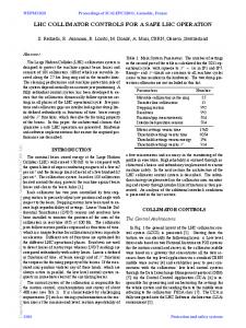
Collimator Designs The collimator shapes studied are part of the ESA Wakefield test programme at SLAC[5], a schematic of the slot type are shown in Figure 1. The two slot types shown are step collimators and tapered collimators. Table 1 describes the dimensions used for the calculations. Slot Type
Side view
Beam view α=π/2rad
Step 1
38 mm
Abstract
Gap
7 mm
Gap = 3.8mm r=1.4mm 4mm – 8mm
h=38 mm α=168mrad
Taper 2
Gap
Gap = 3.8mm 4mm r=1.4mm
Length
– 8mm
Xmm
208mm
Figure 1: Collimator schematic diagram. Table 1: Collimator jaw descriptions Collimator
Type
Gap
Length
Slot 1
Taper
8mm
~100mm
Slot 2
Taper
4mm
~100mm
Slot 4
Step
8mm
7mm
Slot 5
Step
4mm
7mm
Slot 6
Shallow Taper
4mm
~200mm
03 Linear Colliders, Lepton Accelerators and New Acceleration Techniques A03 Linear Colliders
709
MOPLS070
Proceedings of EPAC 2006, Edinburgh, Scotland
SURVEY OF EXISTING TOOLS
MAFIA Longitudinal Wakepotential Tapers 5mm Bunch 6.0
4.0
2.0
Wake Potential (V/pC)
To predict the wakefields associated with various collimator designs, one must have resolution that allows the structure of bunches to play a part. In the ILC, mesh size must be