NuMesh: A Communication Architecture for Static Routing David Shoemaker, Chris Metcalf, and Steve Ward MIT Lab for Computer Science 545 Technology Square #631 Cambridge MA 02139 617-253-6031 fax: 617-253-7359
[email protected],
[email protected],
[email protected]
Keywords: scalable network, off-line routing, parallel processing Abstract The NuMesh system defines a high-speed communication substrate optimized for off-line routing. By determining possible communication paths at compile time, highly efficient hardware and software constructs can be exploited to yield superior network performance. Limited gate delays between NuMesh registers, as well as single cycle message transfers, allow for a high clock frequency and low network latency. A highly pipelined architecture for this communication is presented and a mechanism for efficient flow control communication is discussed. A unique communication protocol is presented and shown to provide single cycle transfers between nodes. Virtual pipes are discussed as a communication protocol for nodes to communicate when running applications on the NuMesh system. Preliminary results and a description of the current hardware and software status are listed.
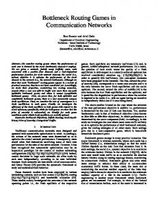
1.0 Background The NuMesh system acts as a scalable, high-speed communication network optimized for static routing. Each NuMesh node contains a programmable communication finite state machine (CFSM) to mediate communications with neighboring nodes. Off-line analysis of inter-node communication provides separate communication instructions, loaded during bootup, for each NuMesh node. Each CFSM provides control signals for its node during each cycle of a globally synchronous clock, allowing read and write operations to occur in a fixed cyclic pattern with a common period. A processor is attached to each NuMesh node, while the NuMesh CFSM serves to provide a number of statically scheduled virtual communication channels between the processing elements. Each NuMesh node can be connected to up to six other nodes providing a base platform for a scalable, three-dimensional, parallel processing machine. Individual NuMesh nodes can be connected like legos, with each NuMesh node allowed to have a different processing element. While not ideally suited for applications making a large number of dynamic decisions, NuMesh will provide exceptional performance for applications that take advantage of static communication. Because the requirement of off-line routing leads to limited run-time routing decisions, the NuMesh architecture can be heavily pipelined, resulting in a very fast communication cycle. In addition, off-line routing can minimize delays caused by congestion, since communication paths are known at compile time. This paper describes some of the hardware and software techniques that allow NuMesh to take advantage of static routing. 2.0 Hardware Overview A NuMesh node contains a finite state machine designed to execute control instructions for every static communication thread that flows through the node. Attempting to keep track of this state information in a single FSM could prove quite expensive as the number of states of the CFSM would be proportional to the product of the number of states in each of the individual threads. In addition, limited dynamic decisions allowed for a particular static thread would affect the state of the entire CFSM. An obvious solution to this problem is to break up the CFSM into a number of smaller FSMs, each charged with the responsibility of a single communication thread. This insight leads to two possibilities. First, the individual FSMs could be replicated in hardware allowing true parallelism. Each replicated FSM could issue independent non-conflicting control signals for its particular static thread. The second approach involves using a single FSM timesliced among a number of independent virtual communication threads. Threads requiring greater bandwidth could be called more frequently by the scheduler. Strict adherence to either of the two approaches would yield unacceptable constraints on the CFSM. The first approach limits the number of communication threads to the number of physical FSMs implemented. The second approach allows an unlimited number of virtual threads, but interleaves them sequentially. Our approach combines both ideas. We allow two physical pipelines to operate concurrently, allowing each pipeline thirty-two independent virtual threads. Each controller is thoroughly pipelined for maximum throughput with the longest delay path being a minimum number of simple logic gates plus either a cross-chip transfer or a small SRAM read/write operation. A schematic of the architecture for one of the controllers is included in figure 1.
NuMesh: A Communication Architecture for Static Routing
Schedule RAM
next state # state # to other pipeline...
Instruction RAM
State #
OP sources destinations read control control logic
Buffers/ Registers input word proc reg word
State #
write control
source reg write data write control
write back logic
FIGURE 1.
Hardware Architecture
The CFSM is structured as two parallel 4-stage pipelines sharing a common first stage. The diagram shows a single controller pipeline, omitting the other pipeline for clarity. Much detail, including paths for preloading the two RAMs, is also omitted. The functions of the pipeline stages are described below.
NuMesh: A Communication Architecture for Static Routing
2.1 Scheduler The scheduler generates, for each clock cycle, the identifier of the virtual thread to be processed by each pipeline. Its major component is a static RAM whose words each contain two fields that are indexes into the instruction RAMs for each of the controller pipelines. An additional field of each word provides the schedule RAM address for the following clock. The schedule RAM contents thus define an outer control loop of fixed size (bounded by the schedule RAM size), and the allocation of threads in each controller pipeline for each clock cycle within that outer loop. Although variations are possible, typically all nodes in a mesh will have scheduling loops of identical size. 2.2 Instruction Lookup There is one instruction RAM for each controller pipeline. Each instruction RAM holds one instruction per thread. Each instruction contains a type of move, a source, and a destination. Source and destination fields will usually decode to one of the six data ports of the CFSM. Small sets of registers and the various pipeline RAMs may also be encoded in the instruction’s operands. 2.3 Read During this stage, the source number is decoded, and an input datum is fetched. An input word can be fetched from the bidirectional ports of the CFSM, a set of buffer registers, or a small set of processor interface registers. Depending on the type of move selected, the valid bit or an additional status bit may be used to help determine from where the source word should come. These moves are further discussed in the Communication Overview section of this document. To be able to support worm hole routing, there must be some amount of buffer storage on a NuMesh node. The NuMesh system supports one word of buffer storage for every communication thread. When attempting flow control routing, these buffer registers are checked in parallel with the appropriate data port for a valid word during the read stage. If a valid word is found in a thread’s buffer register, the thread must have buffered valid data on a previous communication attempt. In this case, the source word is taken from the buffer register rather than the data port. This ensures that a message is not sent out of order and that no words of a message are lost. 2.4 Write The write stage decodes the destination field and writes the source datum to some destination. If a bidirectional port of the CFSM is selected as a destination, the success of the write depends on the type of move selected and the setting of certain status bits. If the destination is a buffer register, the write is guaranteed to succeed. If the destination is a processor interface register, the write will succeed based on the type of move and the processor register’s valid bit. In addition, the destination can also be any of the RAMs in the pipeline. In these cases, the source word contains both the address and data that will be written to the receiving RAM.
NuMesh: A Communication Architecture for Static Routing
When attempting to send words via worm hole routing, there is a chance that a write operation will fail for a particular node. In this case, the word must be written into the thread’s buffer register, and the write will be tried again the next time the communication thread is scheduled. 2.5 Datapath The datapath of the CFSM consists mainly of the CFSM’s six bidirectional data ports. During the read and write stages of the pipeline when the ports are utilized, tri-state buffers control communication between the controller pipelines and the data ports. Communication to the CFSM’s host processor occurs through a small register file. A picture of the datapath is shown in Figure 2. It should be noted that the input and output data ports for each direction are actually the same bidirectional port. to pipe 1 from pipe 1
r1
r2
w1
w2
to pipe 2 from pipe 2
Processor Registers
x-
x-
16x33 w3
x+
r3
x+
y-
y-
from proc
y+
y+
to proc
z-
z-
z+
z+
to src register pipe 1
to src register pipe 2
from src register pipe 1
from src register pipe 2
FIGURE 2. Datapath By carefully orchestrating the timing of the controller pipelines, data can also be transferred between the pipelines or even between threads. Since the ports are bi-directional, one thread in a pipeline can be writing a port while the thread in the opposite pipeline can be reading the same data.
NuMesh: A Communication Architecture for Static Routing
Similarly, two threads in the same pipeline can be reading and writing the same data at the same time. This allows a simple way for mechanisms like copying data to be supported. 3.0 Communication Overview By taking advantage of static routing, a fast and unique protocol can be utilized. Every cycle that a node is expecting to receive a word of data, it issues an accept bit to the node from which it expects to receive the data. Similarly, every cycle a node tries to send data, it sends a valid bit to the receiving node. Therefore, every cycle, a communication can occur, and the success or failure of the transfer can be figured out at a later time. A traditional communication system’s data transfer would involve two cross-chip transfer times due to a request and an acknowledge that must occur in sequence. The NuMesh system can reduce this time to a single cross-chip transfer by exploiting the off-line routing data stored in the CFSM at bootup. This allows a very fast cycle time, and a single cycle transfer for data. The only requirement is that both the sending and receiving nodes act correctly based on the success or failure of a transfer. The protocol for each is described below: 1. Sending Node - The sending node looks at the accept bit to determine the success of its transfer. If the accept bit is set, the transfer completed successfully. If not, the transfer failed, and the sending node must try to send the data again later. The data word gets written into a buffer register for later use. There is one buffer register for every thread. The next cycle this thread operates, rather than reading the source word from a port, the thread takes its word from its buffer register. 2. Receiving Node - The receiving node determines if its data is valid by looking at the valid bit it receives from the sending node. The requirement of the receiving node is that if it receives an invalid word, it ignores the word and does not try to pass it to another node on the following cycle. In addition, the receiving node must send the accept bit to the sending node to indicate whether or not it is able to receive a word. To determine this, the receiving node checks the communication thread’s buffer register. If a valid word exists, then the accept line is deasserted and the receiving node takes its word from the buffer register. If it is empty, the receiving node asserts the accept line. The buffer register must be empty because on the next cycle, the receiving node will try to transfer a word to another node and must have a place to buffer the word if that transfer fails.
Figure illustrates the possible outcomes of a flow control transfer attempt and the appropriate action to be taken in each case.
NuMesh: A Communication Architecture for Static Routing
valid data accept
transfer node
valid data accept
Transfer Result read and write succeed
Action nothing, transfer success
read success, write fail
word gets written to buffer register
read fail
node transfers buffer word if valid
FIGURE 3.
Transfer Actions
3.1 Communication Instructions Three types of communication are supported in the NuMesh system: 1. Flow Control - Flow control transfers utilize the protocol described above. They are expected to be the primary means of communication exercised. One restriction on the flow control communication is that a communication thread can operate only every other cycle. The reason for this is an unavoidable pipeline hazard, and our requirement that a single clock cycle involve either a single cross-chip transfer or a small RAM read, but not both. A node will not know whether or not its write succeeds until it receives an accept signal from the receiving node. Meanwhile, the previous stage of the pipeline is attempting a read and must know whether or not the thread’s buffer register is full in order to correctly handle the accept bit for the sending node. This conflict requires a cycle to be inserted between consecutive operations of the same communication thread. One might try to get around this problem by scheduling the same operation in two threads and alternating between the two threads. This will work, but does not guarantee that the data will stay in the correct order. For example, the first thread may buffer a word, while the second thread times things correctly and is able to complete its transfer. This means that the second word got transferred ahead of the first. In order to deal with this problem and still utilize one hundred percent bandwidth, a conditional flow control instruction is implemented. It is described next. 2. Conditional Flow Control - The conditional flow control protocol will be used primarily for the transfer of packets. When reserving bandwidth for the transfer of a packet, the desired effect is to have either all or none of the packet sent. Similarly, if part of the packet gets buffered, then the entire packet should be put in buffer registers. To accomplish this, a conditional flow control instruction is executed. The effect of this instruction is to mimic the transfer success of the instruc-
NuMesh: A Communication Architecture for Static Routing
tion from the previous cycle. For instance, if the previous word was buffered, the current word gets buffered regardless of the accept bit the node receives. Likewise, if the previous cycle failed to yield a valid source word, the current instruction will assume that no valid word is received without looking at the desired port. When sending a packet, the header transfer thread would be a normal flow control instruction, while the body words would be transferred with conditional flow control instructions. An important result of the conditional flow control instruction is that a single communication pattern can be operating at full bandwidth. This would be accomplished by having two threads both with the same source and destination, but with the first transfer using a normal flow control transfer while the second would be a conditional flow control instruction. Effectively, messages with packet sizes of two would be transferred. When the network is not backed up, a word of data would be transferred every clock cycle. 3. No Flow Control - Flow control can also be turned off resulting in data being blindly transferred from node to node. The validity of such data can be examined by the processor or completely ignored in the case of purely static models such as simple video streams. 4.0 System Communication Various approaches may be taken to communications in the NuMesh. One simple and efficient approach is to use virtual pipes. Virtual pipes connect two (or more) processors; the source processor writes data to a particular interface register, and the NuMesh nodes between the source and destination(s) transfer the data through the mesh. Various parameters may be set by the user to optimize the communication schedules in the mesh. The user specifies the desired bandwidth of the pipe, and may also specify a required minimum latency. Pipelines may be set up to move data in singleword units, or in larger packets. The intermediate nodes on the path are then scheduled to communicate periodically, passing the data through the mesh at one cycle per node. If the destination processor is temporarily unable to accept data on the pipe, the flits will back up in the mesh wormhole-style until the destination processor resumes reading data. The zero-cost flow control mechanism allows us to send data at the maximum available bandwidth while still performing full flow control in the mesh. The pipelines are interleaved throughout the mesh, multiplexed over the physical channels to provide the desired bandwidth to each channel. A simple case of virtual pipes which maps well onto a number of applications is the nearestneighbor case. With this model, all communications happen between adjacent nodes. Many physical simulations are suited to this model, and a variety of other applications can benefit from it as well; for example, a diffusion parallel model can be used in which subtasks are dynamically passed to neighbors as available. Virtual pipes are ideal for applications with limited, pre-specified connectivity and wellunderstood bandwidth needs. If desired, a more aggressive model can be used, in which pipelines are set up and torn down during the execution of the program. A lower-bandwidth control pipe may be set up which is used to update the schedule RAM and/or the instruction RAM on one or more nodes, and this pipe can then be used at run time to modify the scheduling. For example, once a given pipeline has sent all the data that is necessary, its scheduling cycles may be passed to another virtual pipe
NuMesh: A Communication Architecture for Static Routing
to increase that pipe’s bandwidth. Similarly, a new pipe can be set up if the data communications requirements of the program are varying more dynamically. For even more dynamic applications, the mesh can be used differently, although at some cost in communications efficiency or processor overhead. Fully dynamic routing can be done one of two ways. Nearest-neighbor communications channels can be laid out, and messages routed from node to node by the processor. A header with coordinates or a node ID can be used, or source routing, depending on the application’s preference.This can work acceptably fast when the processors are performing a dynamic routing phase and doing nothing but reading and writing messages to and from the NuMesh interface. An alternate solution is to simply lay down virtual pipes between all processors. However, this solution is generally only useful for small meshes and/or low communications requirements, since the useful bandwidth between any two processors scales inversely with the number of processors. Given reasonable locality of communications, this technique remains useful, since the drop in bandwidth will then be constant. For some applications, a hybrid approach may work well. For example, if most of the communication is well-understood, virtual pipes can be used for the known higher-bandwidth channels. A small amount of bandwidth can then be reserved for unpredicted or infrequent messages; they will be routed nearest-neighbor style by using the processors for routing between the source and destination. 5.0 Results and Current Work A generalized event-driven multiprocessor simulator, nsim, has been developed for the NuMesh project. It uses a modular format, where developers can write code to simulate the processor, the communications element, or the interface between them, without having to know how the internals of the simulator work. At the communications module level, we have written simulator modules that accurately simulate the current architecture, as well as the previous generations of the NuMesh architecture. Also available is a dynamic routing module, which handles oblivious and adaptive routing techniques on a Cartesian, diamond, or generalized shortest-path mesh configuration; this makes comparisons between NuMesh-style and traditional dynamic routing easier to perform. A simple virtual pipes module has also been written, which allows users to do functional simulations at a high level by treating virtual pipes as idealized elements that transfer data at a certain prescribed latency and bandwidth. A simple generic register-transfer communications module is also available to experiment with routing models and examine tradeoffs without writing new simulator modules from scratch. A wide variety of processor-level modules have also been written. The most frequently-used processor module is native object code, which is handled by a portable threads library that creates one thread per node and then runs modules until they block voluntarily or perform I/O. Users are then able to take the C code that they compile for the hardware and run it on their workstation (linked with the simulator) to perform debugging and simple timing analysis. A much more accurate and generalpurpose object module is currently under development, using dynamic compilation of code fragments to allow for modelling various cache and/or TLB models and generate precise timing results. Other
NuMesh: A Communication Architecture for Static Routing
available processor modules include a generic assembly-language module for simple code, a threadbased Tcl module, and a simple module specialized to generating streams of data between processors at specified times. A number of applications have been written. We used the nearest-neighbor communication model to simulate a fault-tolerant diffusion-based traveling salesman problem. Subsets of the problem space are propagated via diffusion through the nodes, and results are returned to the originating nodes. New upper bounds to the answer are continuously diffused throughout the mesh. Node failure is handled by tracking and re-issuing problem subsets that are not solved in a timely manner. Applications with more complex communications requirements are addressed by the virtual pipes compiler. The user provides a list of desired virtual pipes, including source, destination, and bandwidth requirements, and the compiler generates the interleaved communication schedules for each node. (Currently, multiple destinations and latency restrictions are not handled.) Various smaller applications have been successfully handled by the compiler. Current work involves porting some applications from the Stanford SPLASH suite; Water is now running on the simulator. Another ongoing project is designing a modular extensible construction toolkit for NuMesh that will allow the user to wire together various digital signal processing operations (such as FFT) to provide high-speed DSP computations. Acknowledgments Thanks go to Frank Honore and Russ Tessier for ideas used in creating the NuMesh hardware. Mike Connell, Pat LoPresti, and Brad McKesson are thanked for their contribution to the software system. Special thanks to Mike and Frank for reviewing and editing drafts of the paper. This research is funded by ARPA contract #DABT63-93-0008. References Metcalf, Chris. “The Numesh Simulator, nsim”. NuMesh Group, MIT LCS January 1994 Shoemaker, David. “Hardware Architecture and Communication Protocols Optimized for Static Routing”, MIT Workshop on Scalable Computing, August 1995. Ward, Steve, et al. “The NuMesh: A Modular, Scalable, Communications Substrate”, International Conference on Supercomputing, July 1993.
NuMesh: A Communication Architecture for Static Routing