8th IEEE International Conference Humanoid, Nanotechnology, Information Technology Communication and Control, Environment and Management (HNICEM) The Institute of Electrical and Electronics Engineers Inc. (IEEE) – Philippine Section 9-12 December 2015 Water Front Hotel, Cebu, Philippines
Object Locator and Collector Robotic Arm Using Artificial Neural Networks Ana Riza F. Quiros, Alexander C. Abad, Elmer P. Dadios Gokongwei College of Engineering De La Salle University Manila, Philippines
[email protected],
[email protected] Abstract— This paper suggests an artificial neural network approach to an object locator and picker. A robotic arm with two joints and a rotating base will function as a pick-and-place machine. The system follows the following constraints: (1) the base of the robotic arm will be situated at a predetermined and fixed position, hence limiting the area at which it can locate and pick an object and; (2) the object will be placed on a flat surface. The span of the robotic arm will determine this area. Also, it should be noted that the arm’s base and joints can move for limited angles only. The area of interest by the arm will be mapped into grids with coordinates. The inputs to the artificial neural network system will be the coordinates at which the object was positioned. Its outputs will be the angles of each joint of the robotic arm such that it can pick the object at its corresponding position. Index Terms— artificial neural networks, robotic arm, pickand-place
I. INTRODUCTION Robots and robotic systems nowadays have sparked interest of many researchers. Robotic systems can be easily instructed for a command and frees humans from doing repetitive and tedious tasks. Moreover, not only do they work faster than humans but they also do so accurately [1]. A lot of improvements on how to control robots have been done in the past years. Researches regarding the control of the robotic arms and the grasp of their hands have been made [2]. Microcontrollers have been also used and programmed to control robotic arms [3]. A paper made by Talpur and Shaikh [4] implemented a microcontroller-based pick and place robotic system to automate the placing of biscuit trays in furnaces for small food industries. Companies have also done their own contribution to the field of robotics. For instance, an automated robotic arm was implemented instead of hiring additional persons for a more productive packaging system [5]. Some robots employ vision systems to locate objects. An edge detection algorithm using a camera was used to measure the distance between an object and a robotic arm. This selfcontrolled robotic arm was able to grip a target object and place it in a paper holder [6]. In the field of medical science,
978-1-5090-0360-0/15/$31.00 ©2015 IEEE
robots have become helpful as well. A flexible robotic arm with a vision system was designed for an orthopedic robot [7]. Development of robots serving meals in restaurants has also been done in a paper of Huang. With a binocular vision system, the meal service robot was able to grip trays [8]. Use of artificial neural networks for the control of robotic systems has been a topic of researches as well. Hulea [9] studied on the use of spiking neural networks to drive humanlike robotic arms. Recurrent neural networks have also been proposed to achieve a flexible grasping motion for a robotic arm [10]. Hierarchical neural networks was also employed in the past to control a robotic arm. In a paper by Rabelo [11], two artificial neural networks, wherein one is at a higher hierarchical level, were designed to plan the movement of the arm. The effects of normalizing the inputs and outputs in a training data set on the control of a robotic arm have also been investigated by Puheim [12]. II. ARTIFICIAL NEURAL NETWORKS Unless a computer is given an algorithm to perform a task, it cannot process data on its own. A computer has 109 transistors and a switching time of a nanosecond. However, a human brain has 1011 neurons but a switching time of a millisecond [13]. Based on these, the computer seems more power powerful than humans. However, it does not have the capability to adapt to new data that needs to be processed differently unless it has been coded. Humans, on the other hand, are able to learn. Artificial neural network (ANN) is a powerful and one of the most effective learning techniques and is inspired by biological neural networks. It attempts to imitate the way information are processed by the human brain. The processing elements of the artificial neural network are analogous to a neuron in a human brain. These processing elements receive input and multiply it by the weight strength of the connection between successive elements. These are then added in the soma or the body of the processing element and passed on to the next element [14]. The processing element is the building block of an artificial neural network. A model of an artificial neural network is shown in Figure 1.
8th IEEE International Conference Humanoid, Naanotechnology, Information Technology Communication and Control, Envvironment and Management (HNICEM) The Institute of Electrical and Electronics Enggineers Inc. (IEEE) – Philippine Section 9-12 December 20115 Water Front Hotel, Cebu, Philippines
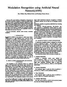
As shown in Figure 2, the object's o location will be fed as an input to the neural network. The T neural network will process this data such that it will outpuut a set of three angles at which each joint angle of the robotic arm should move to accurately reach the aforementioned objecct.
Fig. 1. Artificial Neural Network Moodel
The input layer is a layer of processiing elements that receives the data entering the neural netw work. The hidden layers are all the layers between the input and output layers. These contain elements with varying weightts and have highly parallel connections between other hidden laayers and the input and output layers [15]. The hidden layers cann be considered as a black box, creating a nonlinear relation between b the inputs and the outputs [16]. Lastly, the output laayer is where the output responses exit the neural network. m is trained with a In a supervised neural network, the system set of inputs and outputs. The neural networkk is then tasked to map the inputs to the outputs by inferringg the relationship between the inputs and outputs from given training t data. This type of artificial neural network can be used for pattern recognition and regression or function approxximation. III. METHODOLOGY This paper will focus on training a robotic arm to accurately locate and pick an object withinn the arm's range. This will be accomplished by creating a system with the implementation of artificial neural networks.
Fig. 2. Model of the System
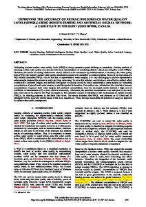
Fig. 3. Flowchart of thhe ANN Implementation
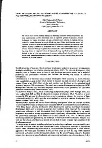
a neural network will be Figure 3 shows how the artificial implemented in the said system m. Initially, a neural network is designed and will be tested for its outputs. Its outputs will then be checked for their accuracy to locate the object. If the output o was successfully located joint angles are such that the object by the arm, the process will end e indicating that the designed artificial neural network is corrrect. Else, a new artificial neural network with different param meters will be designed until it gives the correct output joint angles for corresponding input locations. Figure 4 shows the processs of the artificial neural network as it is integrated in the system m. The training data are gathered initially. When enough trainingg data are collected, they are fed as input to the neural networkk to train it. Once trained, the network will be tested by feeding a set of inputs that are different from the inputs of thhe training data. The outputs of the neural network are compaared to what the actual outputs should be, hence calculating the errors of the network.
8th IEEE International Conference Humanoid, Nanotechnology, Information Technology Communication and Control, Environment and Management (HNICEM) The Institute of Electrical and Electronics Engineers Inc. (IEEE) – Philippine Section 9-12 December 2015 Water Front Hotel, Cebu, Philippines
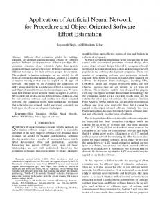
The area of interest by the arm extends 21 cm to the left, right and in front of the robot. Based on the dimensions stated, the region at which the robotic arm can locate and pick an object has an area of 882 square cm. The figure below shows the area of interest by the robotic arm with the mapped grid and coordinates for object location identification.
Fig. 4. Process Flow of ANN
A. Collection of Training Data The figure below shows the robotic arm and the location of each joint along the arm.
Fig. 6. Area of Interest by the Robotic Arm
As can be observed, it has positive and negative xcoordinates for the horizontal while there are only positive ycoordinates for the vertical. This is because the base of the arm has a range of movement of 180 degrees only, hence limiting the range of the arm to the area in front of it.
Fig. 7. Top View of Area of Interest Fig. 5. Robotic Arm
Joint 1 can move from -25 degrees to 25 degrees with respect to the horizontal. On the other hand, Joint 2 can move within -70 degrees to 130 degrees. The base, however, rotates from 0 to 180 degrees.
The hardware mentioned above will be the source of the data for the inputs and the desired outputs or training data for the artificial neural network system. The inputs of the artificial neural network system will be the coordinates consisting of an x- and a y-coordinate at which the object is positioned. The outputs, on the other hand, will be the angles, which are
8th IEEE International Conference Humanoid, Nanotechnology, Information Technology Communication and Control, Environment and Management (HNICEM) The Institute of Electrical and Electronics Engineers Inc. (IEEE) – Philippine Section 9-12 December 2015 Water Front Hotel, Cebu, Philippines
measured manually, at which the two joints and the base must be positioned to reach and pick the said object. B. Training Process Through supervised artificial neural networks, the system will be trained by feeding the inputs (object's coordinates) and the desired outputs (joint and base angles). The input training data matrix consists of 2 rows and 60 columns. The first row and the second row of the input matrix correspond to the x- and y-coordinate of the object's location, respectively. Each column of the said matrix represents one input training datum. Hence there are 60 columns for 60 input training data. The output training data matrix is a 3 by 60 matrix. The three rows represent the base angle, the first joint angle and the second joint angle. It has the same number of columns as the input matrix so that each output corresponds to an input of the same column number. These are fed to the neural network for training. The weights will be calculated by the neural network. The defined number of layers is three. Hence, there is only a single hidden layer with 30 neurons.
system overtime. The training of the system stops when the validation MSE stops decreasing which, as observed in the plot is at epoch 9.
Fig. 9. Validation Checks
The plot shows how the neural network progressed through its calculations. Shown is at least fifteen iterations done by the system. As seen, at epoch 10, the validation failure started increasing and never went down again. Hence in the performance plot of the network, the training stopped at the ninth iteration.
C. Testing Process The testing involved presenting only the inputs to the neural network and identifying if the output joint angles can reach the object's position. IV. EXPERIMENT RESULTS The artificial neural network's output angles after it has learned and been trained are compared to the actual output angles that were manually measured. The performance of the system is measured by calculating the error or the difference between the output angles of the neural network and the measured angles. Fig. 10. Training Data Regression Plot
The plot above shows the regression data. As seen, the value of R is close to neural network has processed the data values of its outputs are approaching the training data outputs.
plot of the training 1 which means the accurately and the value of the actual
Fig. 8. Performance of ANN
Figure 8 shows how the network improved its performance while it was being trained. The performance is measured in terms of the mean squared error (MSE) for each epoch. As can be seen, the MSE decreased as the number of epochs increased, implying an improved performance of the
Fig. 11. Test Data Regression Plot
8th IEEE International Conference Humanoid, Nanotechnology, Information Technology Communication and Control, Environment and Management (HNICEM) The Institute of Electrical and Electronics Engineers Inc. (IEEE) – Philippine Section 9-12 December 2015 Water Front Hotel, Cebu, Philippines
Figure 11 shows the regression plot of the test data. The line of best fit of the neural network outputs is near the target line. However, some of the outputs do not lie on the line of best fit.
zero, it can be observed from the graph that there are some outliers whose errors reach as high as -30 degrees.
Fig. 14. Error Histogram of ANN
Fig. 12. Regression Plot of ANN
The figure above shows the regression plot of the system which plots the network's outputs in comparison to that of the training data outputs. The blue line plots the line of best fit for the neural network’s outputs. The dotted line represents the training data outputs. As observed, the line of best fit nearly coincides with the dotted line, signifying that the network has substantially learned to fit the relationship between the inputs and the outputs of the training data.
Figure 14 plots the distribution of error made by the neural network. As seen, most of the errors occur near zero which implies that most of the neural network outputs are accurate and nearly correct. V. DISCUSSION AND ANALYSIS OF RESULTS The results of the experiments showed that the designed artificial neural network for an object locator and collector robotic arm was able to find the relationship between the network's inputs (i.e. the object's coordinates) and outputs (i.e. the base and joint angles of the robotic arm). Although there are no straightforward relationships between the input and outputs, the neural network was able to fit reasonable output angles with corresponding input coordinates to properly locate the object. The neural network nonlinearly predicted the appropriate outputs for a given set of inputs. However, it should be noted that errors are still apparent in the outputs of the network. The outputs of the neural network as it was fed with the input training data are compared against the output training data to measure its accuracy. Also, some outliers were present in the neural network's output. These outliers are outputs with large errors. Yet, most of the neural network’s outputs have errors approaching zero signifying that most of its predicted outputs are nearly correct. Moreover, the mean errors of the outputs are minimal.
Fig. 13. Output Angle Errors
VI. CONCLUSIONS AND RECOMMENDATION
Figure 13 plots the errors of the output angles of the neural network with respect to the outputs of the training data. The base angle errors, joint 1 angle errors and joint 2 angle errors have a mean of -2.9694 degrees, -1.0219 degrees and -3.0618 degrees, respectively. Even though the mean errors are close to
The designed artificial neural network was able to learn the relationship between the input coordinates and the output angles as shown by the results. However, there are some inputs to the neural network that it cannot accurately process to give a reasonable output. This can be improved by adding more training data to the system so that the calculated weights by the
8th IEEE International Conference Humanoid, Nanotechnology, Information Technology Communication and Control, Environment and Management (HNICEM) The Institute of Electrical and Electronics Engineers Inc. (IEEE) – Philippine Section 9-12 December 2015 Water Front Hotel, Cebu, Philippines
neural network can be corrected. These additional training data can help the neural network to decide on which weights to converge to will be correct. Also, adding more hidden layers and more neurons to each layer can help solve this. However, adding hidden layers should be done with precaution as having too many hidden layers for a given set of training data might result to the system becoming under-characterized since there are no enough training data to set the parameters of the increased number of hidden layers. Hence it is more advisable to increase the number of neurons for the each hidden layer instead. In addition to that, the research about the normalization of training data before the network processes them can be implemented such that the inputs to the network will have boundary values. Such can also improve the speed at which the network will process the training data. Future research about the application of the designed neural network can be used for automation systems that employ pickand-place machines and vision systems. For instance, a camera focusing on an object of interest will capture an image and detect the mentioned object. The pixels of the captured image are analogous to the designed neural network's input coordinates. Hence locating the object can be done by detecting the pixel at which the object appears in the image. A pick-andplace machine, a robotic arm for instance, can automatically move by itself using the position of the object in the captured image. Using the artificial neural network, the machine will learn by itself how it would move based on the position of the object in the image. Hence, less human involvement and intervention will be needed to control the machine. REFERENCES [1] "The European robotics initiative for strengthening the competitiveness of SMEs in manufacturing by integrating aspects of cognitive systems," unpublished. [2] J. Saut, M. Gharbi, J. Cortes, D. Sidobre and T. Simeon. (2010). Planning Pick-and-Place Tasks with Two-Hand Regrasping. 2010 IEEE/RSJ International Conference on Intelligent Robots and Systems (IROS). Taipei: Taiwan.
[3] M. Omar. (2007). Pick and Place Robotic Arm Controlled By Computer. Malaysia. [4] M. Talpur and M. Shaikh. (2012). Automation of Mobile Pick and Place Robotic System for Small Food Industry. [5] A. Felker, "Design and implementation of an automated pick and place system for Johanson Technology, Inc.," unpublished. [6] G. Huang, H. Lin and P. Chen. (2011). Robotic Arm Grasping and Placing using Edge Visual Detection System. 2011 8th Asian Control Conference (ASCC). Kaohsiung: Taiwan. [7] M. Mariappan, T. Ganesan, M. Iftikhar, V. Ramu and B. Khoo. (2010). A Design Methodology of a Flexible Robotic Arm Vision System for OTOROB. 2010 2nd International Conference on Mechanical and Electrical Technology (ICMET). Singapore. [8] G. Huang, X. Chen and C. Chang. (2013). Development of Dual Robotic Arm System based on Binocular Vision. 2013 CACS International Automatic Control Conference (CACS). Nantou: Taiwan. [9] M. Hulea and C. Caruntu. (2014). Spiking Neural Network for Controlling the Artificial Muscles of a Humanoid Robotic Arm. 2014 18th International Conference System Theory, Control and Computing (ICSTCC). Sinaia: Romania. [10] B. Tan, H. Tang, R. Yan and J. Tani. (2014). Flexible and Robust Robotic Arm Design and Skill Learning by using Recurrent Neural Networks. 2014 IEEE/RSJ International Conference on Intelligent Robots and Systems (IROS 2014). Chicago: IL. [11] L. Rabelo and X. Avula. (1991). Intelligent Control of a Robotic Arm using Hierarchical Neural Network Systems. IJCNN-91Seattle International Joint Conference on Neural Networks, 1991. Seattle: WA. [12] M. Puheim and L. Madarasz. (2014). Normalization of Inputs and Outputs of Neural Network based Robotic Arm Controller in role of Inverse Kinematic Model. 2014 IEEE 12th International Symposium on Applied Machine Intelligence and Informatics (SAMI). Herl'any: Slovakia. [13] D. Kriesel. A Brief Introduction to Neural Networks. [14] J. Raol and S. Mankame. "Artificial neural networks: A brief introduction," Resonance, 1996, pp. 47-54. [15] R. Rojas, Neural Networks: A Systematic Introduction, Berlin: Springer-Verlag, 1996. [16] J. Zupan, "Introduction to artificial neural network (ANN) methods: What they are and how to use them," Acta Chimica Slovenica, 1994, pp. 327-352.