In this paper, we use a feed forward artificial neural network to solve the 3D object recognition problem based a set of collected 2D images. Feed forward ANN ...
International Journal of Computer Applications (0975 – 8887) Volume 44– No.5, April 2012
Feature based 3D Object Recognition using Artificial Neural Networks Abdel karim Baareh
Alaa F. Sheta
Mohammad S. Al-Batah
Computer Science Department, Al-Balqa Applied University, Ajloun College, Amman, Jordan
Computer Science Department, The World Islamic Science and Education (WISE) University, Amman, Jordan
Computer Science Department Faculty of Sciences and Information Technology, Jadara University, Jordan
ABSTRACT The recognition of objects is one of the main goals for computer vision research. This paper formulates and solves the problem of three-dimensional (3D) object recognition for Polyhedral objects. A multiple view of 2D intensity images are taken from multiple cameras and used to model the 3D objects. The proposed methodology is based on extracting set of features from the 2D images which include the Affine, Zernike and Hu moments invariants to be used as inputs to train artificial neural network (ANN). Various architectures of ANN were explored to recognize a shape of Polyhedral objects. The experiments results show that 3D objects can be sufficiently modeled and recognized by set of multiple 2D views. The best ANN architecture was twenty input and single output model.
from two-dimensional intensity images, assuming orthographic projection. Authors used a variety of 2D views depicting a 3D object under the case of orthographic projection which was expressed as a linear combination of a small number of 2D views of an object. In [6], authors developed a mathematical models based Takagi Sugano fuzzy membership models to describe the relationship between set features extracted from 2D images of a 3D object and a model class. The mathematical models helped in understanding the characteristics of the model and the advantages of fuzzy modeling in solving such a problem.
General Terms Pattern Recognition, Artificial Neural Networks.
Keywords 3D object recognition, moments, classifications, back propagation.
features
extraction,
1. INTRODUCTION Computer vision systems mainly consider the recognition of 3D objects as a challenging process. Many applications were reported such as the automation on the assembly line, inspection of integrated circuit chips to detect defects in them, security in face and fingerprint recognition, medical diagnosis and detection of abnormal cells that may indicate cancer, remote sensing for automated recognition of possible hostile terrain to generate maps and aids for the visually impaired of mechanical guide dogs. A more detailed list of computer vision applications can be found in [1]. Feature-based 3D object recognition techniques are well known in the literature [2]. These types of techniques found to be successful especially for well structured objects. This means that objects which have unique features or characteristics such as edges can be well recognized. These techniques work, by collecting a set of 2D images for a certain objects (i.e. seen) from various angles and use it for matching purposes. Feature extraction algorithms are used to select the best set of features which can uniquely distinguish the object from the collected 2D images. In fact, pattern recognition techniques normally use gathered information from 2D captured images for an object and do not take in consideration the 3D geometric during the matching process [3, 4]. Many soft computing techniques such as genetic algorithms (GAs) were explored to solve the 3D object recognition problem. For example, in [5], authors investigated the application of genetic algorithms for recognizing 3D objects
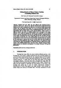
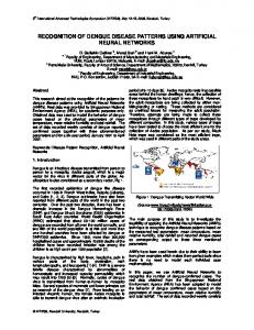
Fig 1: Polyhedral objects In this paper, we introduce our initial idea in developing ANN model which counts on a set of features extracted from 2D images to recognize a set of 3D objects. Figure 1 shows the eleven objects to be recognized using the proposed ANN. Polyhedral objects have been used in order to analyze the performance of the proposed ANN system. Polyhedral objects, under study, consist of eleven 3D objects. The test set contains object of simple 3D shape like box, cylinder, sphere, trapezoid etc.
2. BACKPROPAGATION LEARNING ALGORITHM Recently, ANN have been used successfully to solve a variety of problems such as finance, cancer detection [7], science, forecasting [8], feature extraction [9], classifications [10, 11], face recognition [12], Fingerprint recognition [13] etc. In this paper, we use a feed forward artificial neural network to solve the 3D object recognition problem based a set of collected 2D images. Feed forward ANN normally consists of three types of layers. These layers are the input, hidden and output layers, respectively. A weighted sum of the neuron inputs specifies the activation (i.e. sigmoid) function argument. This activation function is assumed to be nonlinear [14]. Let x1(p), x2(p)....xn(p) be the network inputs, and let y1(p), y2(p),…,yn(p) be the desired output. p is defined as the iteration number.
1
International Journal of Computer Applications (0975 – 8887) Volume 44– No.5, April 2012 The back propagation neural network function can be expressed as [15]:
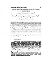
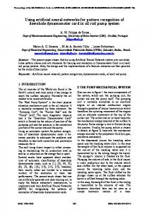
distance from the centre of the turntable, all cameras must have the same focal lengths.
1.
Typically, the height of the video camera is adjusted to be within 1500 mm from the object to obtain a sufficiently large measurement area. However, the camera can be placed at different positions from the object without effecting the image’s feature extraction as the moments features are invariant to object rotation, translation and size scaling in the image. The lens is adjusted accordingly to obtain a clear and sharp image for analysis. The maximum resolution of the input image is fixed to 1024 × 776. After an object of interest is placed at the centre of the turntable, the 2D images of the object are captured and stored in a lossless digital format, bitmap (bmp), in the computer memory. Each rotation, the object will rotate 50o and so on until 360o is completed. Hence, for each object, 72 image sets are obtained.
Calculating the output from the hidden layer as shown in Equation 1.
y j ( p) sigmoid [i 1 x i ( p)wij ( p) j] n
(1)
where n is the number of inputs of neuron j in the hidden layer number, wij are the weights between the input layer and the hidden layer and between the hidden layer and the output layer, θ is a threshold value. The sigmoid function adopted in this study is given in Equation 2.
y j ( p)
1 x ( p) 1 e j
(2)
2. Calculating the output from the output layer as shown in Equation 3.
y k ( p) sigmoid [ j 1 x jk ( p) w jk ( p) j] m
(3)
where m is the number of inputs of neuron k in the output layer 3. Calculating the Error Gradient from the output layer as seen in Equation 4.
k ( p) yk ( p)[1 yk ( p)]ek ( p)
(4)
where ek(p) is the error at the output layer.
ek ( p) y d , k ( p) yk ( p)
(5)
4. The ANN weights can be computed as given in Equation 6.
w jk ( p) y j ( p) k ( p)
(6)
To readjust the weights of the ANN we use Equation 7.
w jk ( p 1) w jk ( p) w jk ( p)
(7)
To calculate the gradient error in the hidden layer we use Equation 8. i
j ( p) y j ( p)[1 y j ( p)] k ( p)w jk ( p)
(8)
k 1
5. Calculating the weights again from Equation 9.
wij ( p) xi ( p) j ( p)
(9)
Again we readjust the weights as given in Equation 10.
wij ( p 1) wij ( p) wij ( p)
(10)
3. CAMERA OBJECT SETUP In this section, a methodology for camera object setup is presented. Each selected object is positioned in its stable condition at the centre of the turntable. The turntable is a circular horizontal platform that can be rotated 360 degree. Illumination using controlled lighting condition is provided to get the image of an object. This is how we can avoid shadow and reflection on the images. Three CCD cameras were used to obtain a number of 2D images of the 3D objects. Camera 1 was fixed at the top of the object, while cameras 2 and 3 were fixed at 45o from perpendicular view. The camera-object setup is shown in Figure 2. Since all cameras have the same
Fig 2: Hardware setup for image acquisition [16]
4. FEATURE EXTRACTION Moment is considered significant features for object recognition. Each object can be recognized if carefully selected features are chosen [17-19]. 2D moments are simple mathematical features to be computed [20]. The object surface area, position, orientation can describe the main characteristics of an object [21]. Various types of moments were presented in the literature. They include Hu moments [22], Zernike moments [23], and Affine moments [24] which were used in many object recognition applications. In this paper, we adopted seven Hu [22], eleven Zernike [23], and six Affine moments [24] features to recognize the 3D objects.
4.1 Hu Moment Invariants In this study, we used the geometrical moments for feature extraction in 3D object shape classification. The invariance property of Hu, Zernike and Affine moments against geometrical transformations like scaling, translation and rotation makes it a good candidate of feature extractor to be used for object recognition. The ease of the 2D moment computation helps reducing the processing time and increases the system effectiveness and for real time computer simulation. In order to understand how to utilize moment invariant method, let fb be a binary digital image with size M × N (i.e. where M and N are the image width and height, respectively) and fb(x,y) is the grey level value for the pixel at row x and column y. The two-dimensional moments of order (p+q) of fb(x, y) which is variant to the scale, translation and rotation is defined as M
N
m pq x p y q f b ( x, y )
(11)
x 1 y 1
2
International Journal of Computer Applications (0975 – 8887) Volume 44– No.5, April 2012 The central moments of order (p +q) of fb(x, y) is defined as M
N
pq ( x xc ) ( y yc ) f b ( x, y) p
q
(12)
x1 y 1
where xc and yc are the centre of mass of the object defined as:
xc
m10 m00
yc
3.
m01 m00
(13)
The moment invariant under scale is defined as
pq
'pq ' ( 00 )
Calculating the value of Hu moments φ1–φ7 according to Equations 18 until 24.
Zernike moments are defined over a set of complex polynomials which is a complete orthogonal set over the unit disk x2+y2≤1 and can be denoted as in Equation 25.
m 1
pq
(16)
( p q 2)
Normalized un-scaled central moment is then given by
pq ( 00 )
(17)
f ( x, y)[v
mn
( x, y)] * dxdy
(25)
x 2 y 2 1
(15)
and
pq
ϑ30, using Equation 17. 4.
Amn
pq 1 2
Computing each value of ϑ11, ϑ02, ϑ20, ϑ21, ϑ12, ϑ03, and
4.2 Zernike Moments (14)
where
'pq
The algorithm of Hu moment invariants is implemented in [22]: 1. Calculating the value of xc and yc based on Equation 13. 2. Computing each value of μ00, μ11, μ02, μ20, μ21, μ12, μ03, and μ30, using Equation 12.
where m = 0, 1, 2,…, ∞. f(x,y) represents the pixel value of the image at x and y coordinates, Vmn(x,y) is the Zernike polynomial, complex conjugate is represented by * symbol and n must satisfy two conditions: 1. m − |n| = even, and 2. |n| ≤ m. Zernike polynomial Vmn(x,y) can be expressed in polar coordinate using the relation
Vmn (r , ) Rmn (r ) exp( jn )
(26)
From the second and third order moments, a set of seven invariant moments which are invariant to translation, rotation and scale derived by Hu [22] are:
where (r,θ) denoting as disk unit and Rmn(r) is orthogonal radial polynomial given by
1 20 02
Rmn (r )
(18)
m n 2
(1) F (m, n, s, r ) s 0
2 (20 02 ) 4
(19)
where
3 (30 312 ) 2 (321 03 ) 2
(20)
F (m, n, s, r )
4 (30 12 )2 (21 03)2
(21)
2
2 11
[(30 12 ) 2 3(21 03 ) 2 ] (321 03 )(21 03 )
(22)
[3(30 12 ) (21 03 ) ] 2
6 (20 02 )[(30 12 ) 2 (21 03 ) 2 ] 411(30 12 )(21 03 ) 7 (321 03 )(30 12 )[(30 12 ) 2 3(21 03 ) 2 ] (30 312 )(21 03 ) [3(30 12 ) (21 03 ) 2 ] where
pqwas obtained from Equation 17.
(m s)! r m2s m n m n s!( s)!( s)! 2 2
(28)
for a digital image fb(x,y), Expression (25) can be denoted with
5 (30 312 )(30 12 )
2
(27)
s
Amn
m 1
f ( x, y)[V b
x
mn
( x, y)]*
(29)
y
Pejnovic et al. [23] derived Zernike moments in terms of central moments as shown in Equation 12. Up to the 4-th order (p +q < 4), the Zernike moments are given by: (23)
S1 A20 (24)
3(2( 20 02 ) 1)
S2 A22 2
S 3 A33 2
9((20 02 )2 4( 11)2 )
2
16(( 03 3 21 ) 2 ( 30 312 ) 2 )
2
(30)
(31)
(32)
3
International Journal of Computer Applications (0975 – 8887) Volume 44– No.5, April 2012
S 4 A31 2
S5
144(( 03 21 ) 2 ( 30 12 ) 2 )
(33)
2
A33* A313 A33 ( A31* ) 3 13824 4 (( 03 3 21 )( 03 21 )( 03 21 ) 2 3( 30 12 ) 2 ( 30 312 )( 30 12 )
(34)
( 30 12 ) 2 3( 03 21 ) 2 ) * S 6 A312 A22 ( A31* ) 2 A22 864 3 ((02 20 )(03 21) 2 ( 30 12 ) 2 411( 03 21) 2 )(30 12 ))
25
S7 A44 2
2
(( 40 622 04 ) 2
2
25
S9 A40
5
* * S11 A42 A22 A42 A22 30 2 (4( 04 40 ) 3( 20 02 )( 02 20 ) 411 (4( 31 13 ) 311 ))
(36)
I5
(37)
(38)
(39)
(40)
The six Affine adopted moment invariants features presented in [24] are defined as follows: (41) 1 2
( 2002 11)
I6
1 6 00
2 2 11 02
3
2 30
2 ( 4004 43113 322 )
(45)
1
( 400422 2312213 9 00 2 2 3 4013 0431 22 )
(46)
The algorithm of Affine moments is implemented as given in [24] and summarized as follows: 1. 2.
4.3 Affine Moments
4 00
(44)
12 6 30 21 02 )
The following conditions were adopted for calculating the Zernike moments as presented in [23]: 1. Calculating the value of xc and yc based on Equation 13. 2. Computing each value of μ00, μ11, μ02, μ20, μ21, μ12, μ22, μ03, μ30, μ31, μ13, μ40, and μ04 using Equation 12. 3. Calculating the value of Zernike moments S1–S11 according to Equations 30 until 40.
I1
2 8113 0330 6 20 022 3012 9 20 022 21 2 11 02 30 12
6( 20 02 ) 1) * 2 S10 A*44 A422 A44 ( A42 ) 250 3 (( 40 6 22 04 )(4(( 04 40 ) 3( 20 02 ) 2 ) 4(4( 31 13 ) 311) 2 )
(43)
6 2011 0230 03 18 2011 02 2112
(35)
(4( 04 40 ) 3( 20 02 ) 2
(6( 402 22 04 )
1 ( 20 ( 21 03 122 ) 11( 30 03 2112 ) 007 02 (3012 212 ))
I3
1 3 ( 20 032 6 202 1112 03 11 00 2 6 20 21 02 03 9 202 02122 12 20112 03 21
2
4(4( 31 13 ) 3( 11) 2 ) 2
(42)
I4
16( 31 13 ) ) S8 A42
1 2 2 (30 03 630 2112 03 430123 0010 4 03 213 3 212 122 )
I2
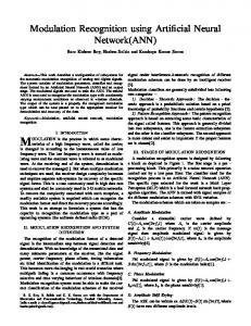
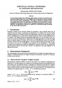
Calculating the value of xc and yc based on Equation. 13. Computing each value of μ00, μ11, μ02, μ20, μ21, μ12, μ22, μ03, μ30, μ31, μ13, μ40, and μ04, using Equation 12. 3. Calculating the value of Affine moments (I1–I6) according to Equations 41 until 46. In this paper, 20 moment features are extracted. The features include 7 Hu moments (Q1-Q7), 7 Zernike moments (S1-S7), and 6 Affine moments (I1-I6). After the feature extraction process, the 20 features are then fed as input data to the feed forward artificial neural network for the classification stage. Figure 3 and 4 show the collected features measurements which will be used for ANN training purposes. We had 396 examples for training and the same number of examples for testing. The 20 inputs are shown with many variations. -1.5
0
-2
-10
-2.5
0
100
200
300
400
-20
0
-10
-20
-20
-40
0
100
200
300
400
-30
-20
-10
-40
-20
-60
0
100
200
300
400
0 -20 -40
-30
100
200
300
400
0
100
200
300
400
0
100
200
300
400
0
100
200
300
400
0
100
200
300
400
24 22 0
100
200
300
400
20
50
60
40
40
30
0
0
100
200
300
400
20
Fig 3: A set of first ten features used in the learning process (f1 to f10) 4
International Journal of Computer Applications (0975 – 8887) Volume 44– No.5, April 2012
60
150
50
100
40
50
0
100
200
300
400
120
70
100
60
80
0
100
200
300
400
50
-6
-20
-6.5
-40
-7
0
100
200
300
400
-60
-10
0
-20
-20
-30
0
100
200
300
400
-40
-8
100
-10
90
-12
0
100
200
300
400
80
wij
x1 0
100
200
300
400
w jk
y1
x2 0
100
200
300
400
0
100
200
300
400
y2 y3
x3
y11
x20 0
100
200
300
400
Input layer 0
100
200
300
400
Fig 4: A set of second ten features used in the learning process (f11 to f20)
5. ANN CLASSIFICATIONS MODEL Our problem is to classify the difference between eleven objects. The collected dataset consists of a total of 792 images which were captured by 3 cameras. These images are separated into two groups. Group 1 has 396 images for training data and group 2 has 396 images for testing data. Images with the camera angles at 0o, 10o, 20o…350o condition are considered for training, and the rest of the images with angles 5o, 15o, 25o…355o condition were considered for testing.
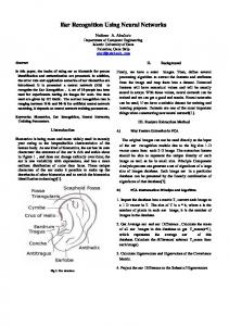
Fig 5: ANN for 20 inputs and 11 outputs
5.2 Optimal Neurons in the Hidden Layer To select the optimal number of neuron in the hidden layer a number of experiments was completed. The network was trained using the BP algorithm with various numbers of neurons in the hidden layer starting with 10 neurons up to 30 neurons, with step 5. We found that the optimal number of neurons in the hidden layer, to achieve minimum error, which found to be 10 neurons with the 11 and 4 outputs and 15 neurons with single output neural networks. The NN developed models are shown in Figures 5, 6, and 7.
5.3 Performance Evaluation All of the proposed network architecture was able to produce the best classification results in both training and testing cases with small number of epochs. We calculated the computed variance-account-for (VAF) for evaluation purposes.
wij
x1
w jk
y1
x2
y2 y3
x3
y4
x20 Input layer
5.1 Neural Network Structure The architecture of the network used for the classification of the polyhedral object is a multi-layer feed forward network. It consists of an input layer, one hidden layer, and an output layer. The input layer contains a number of neuron corresponding to the set of features used which is 20 inputs in our case. The hidden layer consists of nonlinear hidden units and performs nonlinear transformation which is selected to have a variety of neurons. In our case, we tried 10, 15, 20, 25 and 30 neurons in the hidden layer. The hidden units are fully connected to both the input and output. The nonlinearity is provided by the activation function of the hidden units. The activation function was selected as in a sigmoid form. The output layer consists of one output neuron producing the corresponding object classification type. In our case we used 11, 4 and one output. The output layer node has a linear activation function.
Output layer Hidden layer
Output layer Hidden layer
Fig 6: ANN for 20 inputs and 4 outputs
wij
x1
w jk
x2 x3
y1 Output layer
x20 Input layer
Hidden layer
Fig 7: ANN for 20 inputs and 1 output
var( y ) VAF 1 100% var( g)
(47)
where y represents the actual classification values and g is the computed classification values for each output. The computed VAF was 100% in the training cases and almost the same in the testing case for a single output ANN. The neural network back propagation learning algorithm achieved the required goal and was able to minimize the error difference between the actual and estimated response as required. The first two cases, with eleven output and four outputs, produced over 99% recognition rate. The number of neurons in the hidden layers was only ten neurons although in the case of a single output ANN we had to use more neurons in the hidden layers to achieve a better recognition rate (i.e. fifteen neurons).
5
International Journal of Computer Applications (0975 – 8887) Volume 44– No.5, April 2012 to explore the use of other soft computing techniques to solve this problem such as genetic algorithms.
1.5
250
1
Hidden Layer Neurons=10 Hidden Layer Neurons=15 Hidden Layer Neurons=20 Hidden Layer Neurons=25 Hidden Layer Neurons=30
200
Mean Square Error
Mean Square Error
Hidden Layer Neurons=10 Hidden Layer Neurons=15 Hidden Layer Neurons=20 Hidden Layer Neurons=25 Hidden Layer Neurons=30
0.5
150
100
50 0
0
2
4
6
8 10 12 Number of Epochs
14
16
18
20
0
Fig 8: NNs convergence for 20 inputs and 11 outputs
1.5
Mean Square Error
Hidden Layer Neurons=10 Hidden Layer Neurons=15 Hidden Layer Neurons=20 Hidden Layer Neurons=25 Hidden Layer Neurons=30
2
4
6
8 10 12 Number of Epochs
14
16
18
20
Fig 10: NNs convergence for 20 inputs and 1 output
Actual Class and Identified Class 11 10 9 Neural Network Output
Figure 8, 9, and 10 show the convergence curves for the three cases we studied. Various numbers of neurons in the hidden layers were explored to find the optimal set of neurons which can be used for solving the recognition problem. The best found in case one and two were ten and in case three were fifteen as stated before. The actual and estimated classes in both training and testing cases for case 3 (i.e. the ANN with single output) is presented in Figure 11 and 12. The VAF performance evaluation criteria were computed in the two cases. It was found as 100% in the training case and 99.9426% in the testing case. This shows the significant of the proposed ANN models.
0
8 7 6 5 4 3 2
1
1
0
50
100
150 200 250 Training Examples
300
350
400
Fig 11: Training Samples along with identified and estimated classes with a VAF= 100%
0.5
Actual Class and Identified Class 12
10 0
2
4
6
8 10 12 Number of Epochs
14
16
18
20
Fig 9: NNs convergence for 20 inputs and 4 outputs
6. CONCLUSION In this paper, we explored the use of feed forward ANN to solve the 3D object recognition problem. A multiple view of 2D intensity images are taken from multiple cameras and used to model the 3D objects. ANN was used for matching and classification of the 3D objects. A set of features which include the Affine, Zernike and Hu moments invariants are selected to train the ANN. Various ANN structures were explored to achieve the recognition of a Polyhedral objects. The experiments show that 3D objects can be modeled and represented by a set of multiple 2D views. In addition, it does not require complex feature sets for 3D object modeling, thus improve processing time for feature extraction stage. We plan
Neural Network Output
0
8
6
4
2
0
0
50
100
150 200 250 Training Examples
300
350
400
Fig 12: Testing Samples along with identified and estimated classes with a VAF= 99.9426
6
International Journal of Computer Applications (0975 – 8887) Volume 44– No.5, April 2012
7. ACKNOWLEDGMENTS Dr. Mohammad Al-Batah would like to thank Eng. M. Khusairi Osman from University Sains Malaysia, for helping in the 3D data collection. Prof. Sheta is on leave from the Electronics Research Institute (ERI), Cairo, Egypt.
8. REFERENCES [1] Szeliski, R., 2010, Computer Vision: Algorithms and Applications, Springer, New York. [2] Sharath, P., Chitra, D., and Anil, K., R., 1993, Feature Detection for 3D Object Recognition and Matching, In Proceedings, of SPIE Conference on Geometric Methods In Computer Vision II, pp. 366-377. [3] Murase, H., and S. K. Nayar, "Visual Learning and Recognition of 3-D Objects from Appearance", International Journal of Computer Vision 14, 1995, pp. 5–24. [4] Selinger, A. and R. Nelson, "A Perceptual grouping Hierarchy for Appearance-Based 3D Object Recognition", Computer Vision and Image Understanding Vol.76, No.1, 1999, pp. 83–92. [5] Bebis. G, Louis. S, and Fadali. S, 1998, Using Genetic Algorithms for 3-D Object Recognition, In Proceeding 11th Int. Conf. Computer Applications in Industry and Engineering, Las Vegas, NV, pp. 13-16. [6] Sheta, A., Baareh, A. and Al-Batah, M., "3D Object Recognition Using Fuzzy Mathematical Modeling of 2D Images", Accepted for publication at the 3rd International Conference on Multimedia Computing and Systems, May 10-12, Tangier, Morocco, 2012. [7] Braik, M., Sheta, A., "A New Approach for Potentially Breast Cancer Detection Using Extracted Features and Artificial Neural Networks", Journal of Intelligent Computing Vol. 2, No. 2, June 2011, pp.54-71. [8] Baareh, A. K., Sheta, A., AL Khnaifes K., "Forecasting River Flow in the USA: A Comparison between AutoRegression and Neural Network Non-Parametric Models", Journal of Computer Science, Vol. 2, No.10, 2006, pp. 775-780.
Engineering and Computer Science, Vol. I, San Francisco, USA. [13] Darwis, Y. and, Sheta, A., 2008, " Minutiae Extraction for Fingerprint Recognition” In Proceedings of the Fifth IEEE International Multi-Conference on System, Signal and Devices (SSD'08), Amman, Jordan. [14] Baareh, A., Sheta, A, AL Khnaifes K. 2006, "Forecasting river flow in the USA: a comparison between autoregression and neural network non-parametric models", SMO'06 Proceedings of the 6th WSEAS International Conference on Simulation, Modeling and Optimization, pp. 7-12. [15] Michael, N., 2005 Artificial Intelligence: A Guide to Intelligent Systems, Pearson Education Limited. [16] Mat Isa., Zamli, K. Z., and Al-Batah, M. S., "Automated intelligent real-time system for aggregate classification", International Journal of Mineral Processing, Vol. 100, No. 1-2, pp. 41 – 50, 2011. [17] Munoz-Rodriguez, J. A., Asundi, A., and RodriguezVera, R, "Recognition of a Light Line Pattern by Hu Moments for 3-D Reconstruction of a Rotated Object", Journal of Optics and Laser Technology, Vol. 37, No. 2, 2005, pp. 131-138. [18] Realpe, A., and Velazquez, C, "Pattern Recognition for Characterization of Pharmaceutical Powders", Journal of Powder Technology, Vol. 169, No. 2, 2006, pp. 108-113. [19] Rizon, M., Yazid, H., Saad, P., Md-Shakaff, A. Y., Saad, A. R., Mamat, M. R., Yaacob, S., Desa, H., and Karthigayan, M, "Object Detection Using Geometric Invariant Moment, American Journal of Applied Sciences", Vol. 2, No. 6, 2006, pp. 1876-1878. [20] Mat Isa, N. A., Al-Batah, M. S., Zamli, K. Z., Azizli, K. A., Joret, A., and Mat Noor, N. R., "Suitable features selection for the HMLP and MLP networks to identify the shape of aggregate", Construction and Building Materials, Vol. 22, No. 3, 2008, pp. 402-410.
[9] Al-Batah, M. S., Mat Isa, N. A., Zamli, K. Z., and Azizli, K. A, Modified Recursive Least Squares algorithm to train the Hybrid Multilayered Perceptron (HMLP) network, Applied Soft Computing, Vol. 10, No. 1, 2010, pp. 236-244.
[21] Al-Batah, M. S., Mat Isa, N. A., Zamli, K. Z., Sani, Z. M., and Azizli, K. A, A novel aggregate classification technique using moment invariants and cascaded multilayered perceptron network, International Journal of Mineral Processing, Vol. 92, No. (1-2), 2009, pp. 92102.
[10] Seethe, M., Muralikrisha, I.V., Deekshatulu. B. L., Artificial Neural Networks and Other Methods of Image Classifications, Journal of theoretical and applied information technology, 2005, pp. 1039-1053.
[22] Hu, M. K.Visual, 1962, Pattern Recognition by Moment Invariants, computer methods in image analysis, IEEE Transactions on Information Theory, Vol. 8, No. 2, pp. 179-187.
[11] Honjun Lu., Rudy S., huan lui., 1996, Effective data mining Using Neural Networks, IEEE Transactions On Knowledge and Data Engineering, Vol. 8, No. 6, , pp. 957-961.
[23] Pejnovic, P., Buturovic, L., and Stojiljkovic, Z., 1992 Object Recognition by Invariants, In Proceeding of the 11th IAPR International Conference on Pattern Recognition, Vol.2, pp. 434-437.
[12] Radha, V., Nallammal., N, October 19-21, 2011, "Neural Network Based Face Recognition Using RBFN Classifier" In Proceedings of the World Congress on
[24] Kadyrov, A., and Petrou, M., 2001, Object Descriptors Invariant to Affine Distortions, In Proceedings of the British Machine Vision Conference, pp. 391-400.
7