able future. But, things have changed since then: Internet, Embedded, and home ... A special register, named Queue head (QH) pointer, holds the address of the.
On the Design of a Register Queue Based Processor Architecture (FaRM-rq) Ben A. Abderazek, Soichi Shigeta, Tsutomu Yoshinaga, and Masahiro Sowa Graduate School of Information Systems The University of Electro-Communications 1-5-1 Chofugaoka, Chofu-shi, 182-8585 Tokyo, Japan {ben,shigeta,yosinaga,sowa}@is.uec.ac.jp http://www.sowa.is.uec.ac.jp
Abstract. We propose in this paper a processor architecture that supports multi instructions set through run time functional assignment algorithm (RUNFA). The above processor, which is named Functional Assignment Register Microprocessor (FaRM-rq) supports queue and register based instruction set architecture and functions into different modes: (1) R-mode (FRM) - when switched for register based instructions support, and (2) Q-mode (FQM) - when switched for Queue based instructions support. The entities share a common data path and may operate independently though not in parallel. In FRM mode, the machine’s shared storage unit (SSU) behaves as a conventional register file. However, in FQM mode, the system organizes the SSU access as a first-in-first-out latches, thus accesses concentrate around a small window and the addressing of registers is implicit trough the Queue head and tail pointers. First, we present the novel aspects of the FaRM-rq1 architecture. Then, we give the novel FQM fundamentals and the principles underlying the architecture.
1
Introduction
As demand for increased performance in microprocessor continues, new architectures are required to meet this demand. Implementations of existing architecture are quickly reaching their limits as increases in current superscalar Out-of-Order issue are bounded by circuit complexity[9,14,16], and performance increase, due to technology improvement, are approaching their limit. From another hand, the motivation for the design of a new architecture generally arises from the technological development, which changed gradually the architecture parameters traditionally used in the computer architecture. With these growing changes and challenges, the computer architects are faced with answering the question what functionality has to be put on a single processor chip, giving an extra performance edge. Furthermore, as we enter into an era 1
The above architecture embraces multiprogramming languages and will combine the best features of Queue , Register and Stack models of computing.
M. Guo and L.T.Yang (Eds.): ISPA 2003, LNCS 2745, pp. 248–262, 2003. c Springer-Verlag Berlin Heidelberg 2003 �
On the Design of a Register Queue Based Processor Architecture (FaRM-rq)
249
of continued demand for simple, faster and compatible processors, it becomes extremely unpractical and costly to develop a separate processor for each type of application. Queue based architectures ideas were first proposed by Sowa et al. [1,8,15, 17] and Bruno[7,11]. These processors use FIFO data structure as the underlying mechanism for results and operand manipulations; that is, at the execution stage, each instruction removes the required number of operands from the front of an operand Queue (OPQ), performs some computations and stores the result back into the tail of the OPQ. However, for several reasons, theses architectures (Queue based) did not enjoy the success of the conventional Register based (Load/Store) processors. One major reason is that, when the Queue computing model was proposed more than two decades ago, neither Stack based architecture nor Queue computing model seemed to be important paradigms in the foreseeable future. But, things have changed since then: Internet, Embedded, and home network applications are becoming very attractive nowadays. To this end, and in order to meet the demanding requirements of compatibility and high hardware usability relative to single instruction set processor, we have decided to combine the advantages of a novel Queue based architecture with the ones of register-based (load/store) architecture[3,14]. Our proposed architecture will integrate, then, multi executions models in a single shared processor through run time assignment algorithm (RUNFA) without considerable additionel hardware complexity. The above project, which started a couple of years ago at Sowa Laboratory[6], is named functional assignment register microprocessor (FaRM). It features simple pipeline, compact Queue based instruction set architecture, and is targeted for new class of terminals requiring small memory footprints and short programs run-times. The rest of this paper is organized as follow: section two gives the related work. In section three, we give the FQM architecture and computing fundamental. System architecture description is given in section four. Finally, we give our concluding remarks and future work in the last section
2
Previous Work
Queues are well known to computer architecture designers as first-in-first-out data structures. As an attempt to improve overall processor performance, designers have used these structures as matching devices to interface two subsystems with different duty ycles[4]. Queues data structures have also a number of other interesting properties that make them useful in supporting processor design’s functions efficiently. They were proposed to support instructions’ operands and results manipulations in a Queue computing environment. Historically, the idea is traced back to more than two decades. Sowa [1,8,15,18] investigated the design constraints of a superscalar processor architecture based on Queue computation model. Bruno [7,11] also investigated a so called indexed Queue machine architecture that uses Queue
250
B.A. Abderazek et al.
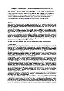
Fig. 1. The Shared Storage Unit as viewed by FQM and FRM modes
as the underlying mechanism for operands and results manipulations. At the execution stage of the above architecture, each instruction removes the required number of operands from the front of the Queue, performs some computations and stores the result back into the Queue at a specified offsets. A major problem with the above architecture is that it requires the relocation of a potentially large number of operands. Also there is a possiblility that the result stored by one instruction may overwrite that of an earlier one.
3
FQM Function Overview
The proposed FQM has operations in its instructions set which implicitly references an operand Queue (OPQ), just as SEM has operations, which implicitly references an operand stack. Each instruction removes the required number of operands from the head of the OPQ, performs some computations, and returns the result to the tail of the OPQ, which is implemented as a circular Queue. The OPQ occupies continuous storage locations and can be dynamically extended. A special register, named Queue head (QH) pointer, holds the address of the first operand in the OPQ. Operands are retrieved from the front of the OPQ by reading the location indicated by the QH pointer. Immediately after retrieving an operand, the QH pointer is automatically adjusted so that it points to the next operand. Results are returned to the tail of the OPQ indicated by a Queue tail (QT) pointer.
On the Design of a Register Queue Based Processor Architecture (FaRM-rq)
251
Fig. 2. FQM Computing Fundamental. The arithmetic operations correspond to the internal nodes of the parse tree and the fetch operations correspond to the leaf node of the parse tree. Note that in FQM mode, instructions [I1,I2, I3, I4] can be first executed in parallel, then [I5, I6] can be simultaneously proceeded . This leads to about 50% speedup.
3.1
FQM’s Queue Manipulation
The Queue manipulation is assured by a Shared Storage Control Unit (SSCU) and is the the backbone of the SSU unit. It performs basically the following four tasks: 1. Checks the data validity bit (DVB) for each OPQ entry 2. Controls the QH, QT and a life Queue head (LQH). The LQH is used to avoid overwriting (Queue overflow) life data within the OPQ. For each returned result , the SSCU compares the QT pointer value to the LQH pointer value and returns the comparison result to FaRM-rq’s issue unit (IU). The issue unit’s hardware uses the above value to issue secure instructions in parallel. 3. Handles the OPQ overflow and underflow 4. Allocates new logical Queue for each context switch.
252
B.A. Abderazek et al. ldw addr(d0) ; assume that "d" is in the location &(addr + d0) ldw addr(d1) ; assume that "e" is in the location &(addr + d1) ldw addr(d3) ; assume that "b" is in the location &(addr + d3) ldw addr(d2) ; assume that "c" is in the location &(addr + d2) add; ldw addr(d3) ;assume that "f" is in the location &(addr + d3) mul div add stw (a) Assembly code for h= b*c + (d+e)/f OPQ_{s0}:-OPQ_{s1}:d OPQ_{s2}:d,e OPQ_{s3}:d,e,b OPQ_{s4}:d,e,b,c OPQ_{s5}:b,c,d+e OPQ_{s6}:b,c,d+e,f OPQ_{s7}:d+e,f,b*d OPQ_{s8}:b*c,(d+e)/f OPQ_{s9}:b*c+(d+e)/f OPQ_{s10}:-(b) Queue Contents at each cycle
Fig. 3. Sample Queue Instructions Sequence
3.2
FQM’s Instructions Generation
The FQM instructions sequence generation can be obtained by traversing a given parse (binary) tree in a new traversal called level-Order-Scan-Tree (LOST)[3]. The LOST traversal is done by visiting the nodes of a parse tree from the deepest to the shallowest levels and from left to right within each level in the tree. In[3, 14] we showed that the FQM’s instructions generation can be used to evaluate an arbitrary expression and the instructions sequence for an arbitrary arithmetic expression can be derived efficiently from the parse tree for that expression. A simple example to demonstrate the basic FQM instruction generations is given in Fig. 2. The (*) is a multiply operator, (+) is an addition operator, and (/) is a division operator. The OPQ contents after each instruction processing is shown in Fig. 2(b). The mul mnemonic is a multiply operation, add is an addition operations and div is a division operations. Notice in the above example that instructions I1, I2, I3 and I4 can be executed in parallel. Instructions I5 and I6 can be also executed in parallel when their operands are available at the OPQ. In FQM mode, independent instructions are dynamically detected and executed in parallel (discussed later). 3.3
FQM Sample Instructions Sequence
The complete mathematical theory for the FQM’s instructions sequence generation can be found in[3,14]. We showed in the above mathematical theory that the FQM instructions sequence can be easily and correctly generated from a
On the Design of a Register Queue Based Processor Architecture (FaRM-rq)
FRM Control unit
FQM Control Unit
Shared Storage Control Unit (SSCU)
Address Multiplexer
Decode and (DU)
DATA/ADDRESS BUS
DATA/ADDRESS BUS
Issue and Resolution Unit (IRU)
Functional Assignment Unit (FAU)
253
Instruction Fetch Unit (IFU)
Shared Storage Unit (SSU) 64x32
ALU
FaRM-rq core
Fig. 4. System Architecture Basic Block Diagram
parse tree. It was also proved in that the FQM can be used to evaluate any given expression. Consider the simple example shown in Fig. 3 (a). In this example, the instructions flow is obtained by traversing the corresponding parse tree using a new traversal called level-order-scan-tree[5]. The OPQ contents at each cycle is given in Fig. 3 (b). Note that the front of the OPQ is on the left. However, in the case of stack execution model, the top of the operand stack is on the left. Also an important difference between the stack execution model and the FQM model is the order of operands for dyadic operators. In the stack model, the left operand of a dyadic operator is pushed first, followed by the right operand. Similarly, on the FQM mode the left operand of a dyadic operator is enqueued first followed by the right operand.
4
FaRM-rq Architectural Overview
As illustrated in Fig. 4, the architecture has a shared storage unit (SSU) consisting of 64 32-bit registers. The machine functions in two different modes and has five pipeline stages. During the first stage, instructions are read from
254
B.A. Abderazek et al.
the instruction memory (Instruction fetch stage). At the second stage, instructions are decoded and assignment of functional unit and storage locations is performed. Instructions are issued in the third stage (Issue). IN FQM mode, the issue hardware must check the OPQ and memory dependencies. The algorithm to check a so called Safe-Issue is as follow: Assume that I1 , I2 , · · · , In−1 , In are instructions which reside in the issue buffer within the issue unit. Assume that: LQH1 , LQH2 , · · · , LQHn−1 , LQHn are the corresponding LQH values of I1 , I2 , · · · , In−1 , In . Assume that: QT1 , QT2 , · · · , QTn−1 , QTn are the corresponding QT values of I1 , I2 , · · · , In−1 , In if QT1 < all(LQH2 , · · · , LQHn ) =⇒ Issue if QT2 < LQH1 and LQH2 ¡ all (LQH3 , · · · , LQHn ) =⇒ Issue ... if QTi < all(LQH1 , · · · , LQHi−1 ) and QTi < all(LQHi+1 , · · · , LQHn ) =⇒ Issue For all inverse cases =⇒ Wait In the fourth stage, instructions are executed (Execute) and the sast stage, the SSU unit is updated and data memory access takes place (write Back). 4.1
Programming Models
The FaRM-rq system works in two different modes and with two programming models: (1) R-mode (FRM): to support conventional register based binary applications and (2) Q-mode (FQM): to support the novel Queue based binary applications. The processor has two control units, one data path, and a mode bit which keeps track of which control unit is to be in operation. The two modes communicate through the SSU unit. A schematic of the two mode views is illustrated in Fig. 1. In FQM mode, each instruction removes the required number of operands from the head of the OPQ, performs a computation and stores its result at the tail of the OPQ. In FRM, the SSU behaves as a conventional register file. However, in FQM, the system organizes the SSU access as a FIFO latches, thus accesses concentrate around a small window and the addressing of registers is implicit trough the Queue head and tail pointers. 4.2
The SSU Design Considerations
In R-mode, the SSU unit is seen as a conventional register file with N registers. The program counter and other special purpose registers are included in the register file. However, in FQM mode, the SSU unit is seen as a circular Queue with N/2 elements as illustrated in Fig. 5.The other N/2 elements are used as storage registers for internal functions. After reset, the kernel will boot in FRM mode. Upon finishing the initialization phase, it switches to FQM mode and executes the Queue programs until
On the Design of a Register Queue Based Processor Architecture (FaRM-rq)
255
Circular Queue 0 63
63
Operand Queue (OPQ)
63
0
PC MDR QHP QTP LQH IRA SCRA a0 ~a3 d0~d3 CCR0 CCR1 SP ICR
program counter mode register queue head pointer queue tail pointer life queue head pointer inturrupt return address subroutine return address address registers r0~r3 data registers d0~d3 Condition Code Regiter0 Condition Code Regiter1 stack pointer inturrupt cause register
0
Fig. 5. SSU Unit when Viewed by the Queue Control Unit (QCU)
(1) an interrupt occurs, (2) an unrecognized instruction occurs or (3) the special designated Queue binary for switching to RQM mode occurs. The FaRM-rq processor continues , then, excution until a ”switchover” instruction clears the mode register (MDR) defining the mode operation. The FQM’s operand Queue is implemented as a circular Queue . When the operand Queue is full, the SSCU continues to use the program memory as storage. 4.3
The SSU Design Trends
Area: The area of the SSU is the product of the number of entries (registers) R, the number of bits per entry, b, and the size of an entry cell. The layout of a register cell, given in Fig. 6 (a), shows that each cell is (w + p)(h + p) girds: (w + p) wire track wide, (h + p) wire track high, p word-line in one dimension, p bit-lines in the other, and wh grids for the storage cell, power, and ground. Each port requires one wire track for a bit-line to access the data. Delay: As with a general register file, the delay of the SSU is composed of wire-propagation delay (WPD) and fan propagation delay (FPD). The WPD is the minimum time of flight across a wire, which grows linearly with distance, assuming optimally spaced repeaters. The fan-in/fan-out delay is the minimum drive delay of a lumped capacitive load using a buffer chain, which grows logarithmically with capacitance[13]. As shown in Fig. 6 (b), to access a register cell within the SSU unit, a signal must traverse a word-line of length (w + p)bR1/2
256
B.A. Abderazek et al.
Fig. 6. Queue Design Trends:(a) Register Cell Access, (b) Register Cell Schematic
and then a bit-line of (h + p)bR1/2 , resulting in a delay that is proportional to pR1/2 . The access time is dominated by the fan-out of the word-line and the fan-in of the bit-line, which is a function of the number of entries within the SSU unit. 4.4
FAU Mechanism
The functional assignment unit (FAU), which is the backbone component of the FaRM-rq architecture, is shown in Fig. 7. The FAU mainly consists of the following components: Binary File Decoder (BFD): The BFD major role is to determine the type of the file being fetched. Mode Analysis: The mode Analysis unit’s major role is set/reset the mode register (MDR) in the mode switch unit, which is responsible for switching between modes and also finding the appropriate execution model for a binary or a part of binary application.
On the Design of a Register Queue Based Processor Architecture (FaRM-rq)
257
Decode Buffer FRM/FSM Binary
FQM Binary
MDR
Mode Analysis
Queue Computation
Functional Assignmnet
Issue Buffer
Mode Switch
Single Analysis FAU Fig. 7. Functional Assignment Mechanism
Queue Computation (QCU): The QCU calculates sequentially the QH and QT pointers for each instruction. The calculated values are used later by the issue unit hardware. Functional Assignment (FA): The FA major function is to allocate functional units and operands locations in the SSU. It contains also the storage manager unit (SAU). The SAU also handles the overflow and the underflow of the OPQ.
5
FQM Instruction Set Architecture
All the instructions are byte addressed and provide access for bytes, half words, words, and double words. Bellow we will discuss the Instructions set design onsiderations for the FQM mode, which is our major concern in this paper. 5.1
Memory Type Instructions (M-Type)
The M-type, shown in Fig. 8, consists of all load and store operations. When data must be obtained from/sent to memory, the M-type instructions are needed. The op field is 6-bit and is used for operation coding. The d field is 2-bit and is used to select one of four data registers. The addr field is 8-bit offset. For load instructions (i.e. lw) the contents of the d registers are added to the 8-bit offset to form the 32-bit address of the memory word. The word is loaded from memory to a Queue entry within the OPQ pointed by the Queue tail pointer (QT). In Fig. 9 (b), the memory instruction would be decoded as load the 8 bit byte at memory location [contents of d0] + 0x52 into the Queue tail pointed by the Queue tail (QT) pointer.
258
B.A. Abderazek et al. Offset added to base address (+/- 128) (7 bits magnitude + sign bit)
Define Operation
M-type
Op Code 6 bits
d/a addr/value/target 2 bits
8 bits
Base address in memory
Fig. 8. Memory instructions (M-type) format
The store instruction has exactly the same format as load, and use the same memory calculation method to form memory addresses. However, for store instructions the data to be stored are found from the head of the operand Queue (OPQ) indicated by the Queue head (QH) pointer. In Fig. 9(a), the memory instruction would be decoded as store the 32 bit word of the OPQ entry indicated by the QH at memory location [contents of d1] + 0x53. Memory Address Extension: In M-type instructions, the offset is only 8bits wide; that is the address space range (from the base address) is only 128 memory slots. This may not be large enough for real applications. To cope with this address ”shortage”, we adopted the idea proposed by Sowa[15]. In the above idea, the compiler uses static optimizations techniques and automatically inserts (when needed) a convey instruction before each load or store instruction. The convey instruction is simply an instruction which forwards its operand (offset) to the consecutive load or store offset field. That is, when a convey instruction is inserted before a load or store instruction, the processor combines the convey instruction offset with the current load or store instruction offset and the Op Code = "stw"
101100
Offset = + 53H(= +83)
01
01010011
Base addess is in d1 (=d1) (a) Op Code = "ldb"
100000
Offset = + 52H (= +82)
00
01010010
Base addess is in d0 (=d0) (b)
Fig. 9. Load and Store instructions internal coding example
On the Design of a Register Queue Based Processor Architecture (FaRM-rq)
259
data register to find the effective address. The convey instruction untilizations is illustrated in Fig. 10. ; address space extension covop 25H ; convey 25H address (offset) ldb 12H(d0) ; load data from mem[25H(12H(d0)] .. .. .. .. addp 4 ; stw 24H(d1) ; store word at mem(24h(d1)) Fig. 10. Address space extention
5.2
Data/Address Register Instructions
The instruction set are designed with four data registers (d0∼d3) and four address (a0∼a4)) registers. These registers are used as base addresses for memory and control instructions respectively. The control instructions, which will be described later, consist of jump, loop, call, and interrupt instructions. The data/address registers are general purpose; that is they are visible to the programmer. These registers are 32-bits wide. Therefore, to set or reset one 32-bits address register, four instructions (sethh, sethl, setlh, setll) are needed. It may seam that the it set/reset operations are costly since four instructions are needed to set one address or data register. However, from our preliminary evaluations, operations on these registers occur not so often within a give application. Figure 11 is an example showing how data register d0 is set with setxx instructions. Note that these instructions have the same format as M-type instructions. The data/address registers can be also incremented or decremented by the inc instruction. The syntax is: inc a, value. This type of instructions belongs to the I-type instructions shown in Fig. 12. Note that the range of the value operand is:−8, −7, · · · , < value ¡ +1, +2, · · · , +8. The I-type instruction also consists of swi (software interrupt) and setr (set register) instructions. 5.3
Control Instructions (C-Type)
The control instructions consist of move, branch, jump, loop, call,interrupt, and barrier instructions. The jump,loop and call instructions have the same format as the previously defined M-type instructions. They all use a register as a base address register and an offset target of eight bits. As with memory instructions, target addresses of these instructions can be extended to sixteen bits by convey instruction. The C-type shown in Fig. 13also has other control instruction with only one operand.
260
B.A. Abderazek et al.
5.4
Transfer Instructions
The FQM supports four types of control flow (transfer) change: (1) BarrierBranch, (2) Jump, (3) Procedure call and (4) Procedure return. As illustrated in Fig. 13, the target address (t) of these instructions is always explicitly specified in the instruction. Because the explicit target (displacement) value, which will be added to the fetch counter to find the real target address (RTA), is only 8-bits the convey instruction’s offset can be combined with the transfer instructions’ explicit target to extend the RTA space. Branch Instruction: The branch instructions belong to the C-type. To avoid having too much work per instruction, the branch instruction resolution is divided into tasks (1) whether the branch in taken (with comparison instruction) and (2) the branch target address (address calculation). One of the most noticeable properties of the FQM branches is that a large number of the comparisons are simple tests, and a large number are comparison with zero. According to the type of the condition the comparison instruction compares two entries obtained from the head of the OPQ and insert the result (true/false) to a condition code
Fig. 11. Address register setting example
Fig. 12. I-type Instruction Format
Define Operation C-type
Op Code 8 bits
t: Target adderess f: action value n: Queue action counter t/f/n 8 bits
Fig. 13. C-type Instruction Format
On the Design of a Register Queue Based Processor Architecture (FaRM-rq)
261
(CC), which is automatically checked by the branch instruction. In our implementation, branches are also barrier instructions. That is, all instruction preceding the branch instructions should complete execution before new instructions (branch successor instructions) can be issued. Barrier Instructions: This type consists of halt, barrier, SerialOn, and SerialOff instructions. These instructions are designed to control the execution and the process type of instructions. Queue Control Instruction (QCI): The QCI consists of stpqh (stop Queue head), stplgh (stop life Queue head autqh (automatic Queue head), and autlqh (automatic life Queue head). These instruction are designed to control the life of data within the (OPQ). 5.5
Producer Order Instructions (P-Type)
This type (P-type) consists of about 70% of the total instructions in FQM execution. The P-type consists of all single and double word computing, logical, compare, and conversion instructions. The format of the P-type instruction is illustrated in the Fig. 5.5. We have to note that both integer and floating-point operations are supported. Define Operation P-type
Op Code 9 bits
n: entry number from the QH n 7 bits
Fig. 14. P-type Instruction Format
6
Conclusions
We have proposed a hybrid processor architecture that supports Register and Queue based instructions set in a shared resources single processor core. Our hybrid architecture addresses important design challenges by featuring two programming models: (1) R-mode (when switched for register based instructions support), and (2) Q-mode (when switched for Queue based instructions support). We have also presented the novel aspects of the FaRM-rq architecture as well as the novel FQM mode architecture. The FaRM-rq architecture is expected to increase the processor resources usability, relative to single instruction set processor and also to support the novel Queue architecture, which is targeted for a new class of terminals requiring small memory footprints and short programs run-times. Our feature work is to investigate the parallelism exploitation and pipelining techniques within the FQM mode. In order to evaluate the real performance and the initial physical estimate of the proposed architecture, real evaluation will take place via several layers of simulation, ranging from high-level models, to logic level models.
262
B.A. Abderazek et al.
References 1. Okamoto S., Suzuki A., Maeda A., Sowa M.: Design of a Superscalar Processor Based on Queue Machine Computation Model. IEEE PACRIM99, (1999) 151–154 2. Sohi G.: Instructions Issue logic for high-performance, interruptible, Multiple Functional Unit, Pipelined Computer. IEEE Trans. on Computers, vol.39, No.3,(1990) 349–359 3. Abderazek B. A., Kirilka N., Sowa M.: FARM-Queue Mode: On a Practical Queue Execution model. Proc. of the Int. Conf. on Circuits and Systems, Computers and Communications, Tokushima, (2001) 939–944 4. Michael K. M., Harvey G.C.: Processor Implementations Using Queues. IEEE, Micro, (1995) 58–66 5. Philip K.: Stack Computers, the new Wave. Mountain View Press (1989) 6. Sowa Laboratory: http://www.sowa.is.uec.ac.jp 7. Bruno R., Carla V.: Data Flow on Queue Machines. 12th Int. IEEE Symposium on Computer Architecture,(1995) 342–351 8. Suzuki H., Shusuke O., Maeda A., Sowa M.: Implementation and evaluation of a Superscalar Processor Based on Queue Machine Computation Model. IPSJ SIG, Vol.99, No. 21 (1999) 91–96 9. Smith J. E., Sohi G. S.: The microarchitecture of Superscalar processors. Proceedings of the IEEE, vol. 83, (no. 12), (1995) 1609–1624 10. Silc J., Robic B., Ungerer T.: Processor Architecture: From Dataflow to Superscalar and Beyond. Springer-Verlag, Berlin, Heidelberg, New York (1999) 11. Periss B. R.: Data Flow on a Queue Machine. Doctoral thesis, Department of Electrical Engineering, University of Toronto, Toronto (1987) 12. Palacharia, Joupi N. P, Smith J.E: Complexity-Effective Superscalar Processor. Ph.D. dissertation, Univ. of Wisconsin (1998) 13. Abderazek B.A., Sowa M.: DRA: Dynamic Register Allocator Mechanism for FaRM Microprocessor. The 3rd International Workshop on Advanced Parallel Processing Technologies, IWAPPT99, (1999) 131–136 14. Abderazek B.A.: Dynamic Instructions Issue Algorithm and a Queue Execution Model Toward the Design of a Hybrid Processor Architecture. PhD. Thesis, IS Graduate School, Univ. of Electro-Communications, (2002) 15. Sowa M.: Fundamental of Queue machine. The Univ. of Electro-Communications, Sowa Laboratory, Technical Reports SLL30305, (2003) 16. Radhakrishnan R., Talla D., John L. K.: Allowing for ILP in an Embedded Java Processor. Proceedings of IEEE/ACM International Symposium on Computer Architecture, Vancouver, CA, (2000) 294–305 17. Sowa M.: Queue Processor Instruction Set Design. The Univ. of ElectroCommunications, Sowa laboratory, Technical Report SLL97301, (1997) 18. Sowa M., Abderazek B.A, Shigeta S., Nikolova K., D. Yoshinaga T. Proposal and Design of a Parallel Queue Processor Architecture (PQP), 14th IASTED Int. Conf. on Parallel and Distributed Computing and System, Cambridge, USA, (2002) 554– 560