interconnected power system considering reheat type turbine in one of ..... [1]
D.P. Kothari and I.J. Nagrath, Modern Power System Analysis, 3rd ed. Singapore
...
MIT International Journal of Electrical and Instrumentation Engineering Vol. 1, No. 1, Jan. 2011, pp. 1-5 ISSN No. 2230-7656 ©MIT Publications
1
Optimal Load Frequency Control of an Interconnected Power System K.P. Singh Parmar
S. Majhi, Member, IEEE,
Assistant Director (Technical) with Centre for Advanced Management & Power Studies, National Power Training Institute, Faridabad, Haryana,India email:
[email protected] m
Professor and Head of the Department of Electronics and Communication Engineering, Indian Institute of Technology, Guwahati, Assam, India
Abstract—Load frequency control is one of the important issues in electrical power system design/operation and is becoming much more significant recently with increasing size, changing structure and complexity in interconnected power system. This paper deals with load frequency control of an interconnected power system considering reheat type turbine in one of the thermal areas. The dynamical response of the load frequency control problem in an interconnected power system under consideration is improved with a practical viewpoint by designing the output feedback controller. The optimal control methods are proposed and their dynamic responses are compared. The results indicate that the proposed controllers exhibit better performance. In fact, the control systems designed on these methods satisfy the load frequency control requirements with a reasonable dynamic response. Keywords—Automatic generation control, area control error, optimal control, reheat turbine.
I. NOMENCLATURE AGC
Automatic gain Control
ACE i
area control error of area i
Prti
rated power capacity of area i
f Di
nominal system frequency system damping of area i
TSG
speed governor time constant
TT
steam turbine time constant
TPS
power system time constant
R
governor speed regulation parameter
K PS
power system gain
KR
steam turbine reheat constant
TR
steam turbine reheat time constant
B
frequency bias parameter
i a12 T12
ith area frequency response characteristics P rt1 Prt 2 synchronizing coefficient
w i PDi incremental load change in area i
D.P. Kothari, Senior Member, IEEE Former Director (in charge) of IIT, Delhi, former Vice Chancellor of VIT University, Vellore. Currently Advisor to Chancellor of VIT University, Velore (TN), India
II. INTRODUCTION In recent years, major changes have been introduced into the structure of electric power utilities all around the world. The successful operation of interconnected power system requires the matching of total generation with total load demand and associated system losses. As the demand deviates from its normal value with an unpredictable small amount, the operating point of power system changes, and hence, system may experience deviations in nominal system frequency (which is due to drooping characteristics of the governor-turbine system) and scheduled power exchanges to other areas, which may yield undesirable effects. There are two variables of interest, namely, frequency and tie line power exchanges which must remain fixed to their nominal values [19, 20]. A literature survey shows that most of the earlier works in the area of AGC pertain to interconnected thermal systems with non reheat type turbines and relatively lesser attention has been devoted to the AGC of interconnected thermal system with reheat type turbines [10]-[14]. In reheat turbines, the reheating may be in a single stage or in multistage .A two area interconnected Thermal-Thermal Power system incorporating reheat type turbine in one of the areas has been considered for study in this paper. The linearised models of governors, reheat turbines and non-reheat turbines are taken for simulation of the system [9]. Probably the most important contribution modern optimal control theory has made to the control engineer is the ability to handle a large multivariate control problem with ease. The engineer has only to represent the control system in state variable form and specify the desired performance mathematically in terms of a cost to be minimized. A unique or best controller in the sense of minimizing the cost may be designed by applying well proven theories and techniques [1]. Application of the optimal control theory to power system has shown that an optimal load frequency controller can improve the dynamic stability of a power system [10].
MIT International Journal of Electrical and Instrumentation Engineering Vol. 1, No. 1, Jan. 2011, pp. 1-5 ISSN No. 2230-7656 ©MIT Publications
In this paper, the dynamical response of the LFC problem is improved with a practical point of view. Because practically access to all of the state variables of system is limited and measurement of all of them is not feasible, an output feedback controller design is also presented in this paper to overcome this problem. The proposed optimal feedback methods are evaluated on a two-area power system. The results of the proposed controllers are compared by means of computer simulations. The result indicates that proposed methods improved the dynamic response of system considered and provides a control system that satisfied the LFC requirements.
III. MATHEMATICAL BACKGROUND Modern control theory is to be applied to design an optimal load frequency controller for a two-area system. In accordance with modern control terminology Pref 1 and Pref 2 will be referred to as control inputs
u1 and u2 . In the
u1 and u2 were provided by the integral of ACEs. In modern control theory approach u1 and u2 will be created by a linear combination of all the conventional approach
system states (full state feedback approach) or a linear combination of states to be controlled/measurable states (output feedback approach) [1].
2
x Ax Bu With x(0) x0
y Cx
(1) (2)
where x is a state vector of dimension n1, n no. of states u is a control vector of dimension m1, m no. of control variables y is a output vector of dimension p 1, p no of output variables A, B and C are constant matrices with appropriate dimensions. The performance of the system is specified in terms of a cost that is to be minimized by the optimal controller. 1 (3) J xT Qx uT Ru dt 20 Where Q is nn positive semi definite symmetric state cost weighting matrix R is mm positive semi definite symmetric control cost weighting matrix The matrices Q and R are chosen appropriately. The optimal controller that minimizes the cost of the system in state variable form is a function of the present states of the system weighted by the components of a constant gain matrix K1 of dimension mn and can be defined by (4) u K x 1
K1 can be obtained from the solution of the reduced matrix Riccati equation given below. 1 T (5) AT P1 P1 A PBR B P1 Q 0 1 1 T (6) K1 R B P1 The acceptable solution of K1 is that for which the system remains stable. For stability all the eigen values of the matrix A BK1 should have negative real parts. From equation (4), we get the optimal control of our choice. So for it was assumed that all the states are available for feedback. Practically it is very difficult and costly to measure and to have readily available information of all the states in most of the large power systems. Usually reduced number of state variables or a linear combination thereof is available. The output feedback controller is as described below
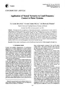
u Ky Fig. 1. State space model of a two-area power system.
The Generalized linear model of the power system may be described in state space form as
(7)
where K is an output feedback gain matrix of dimension (mp). In the optimal control scheme the control inputs are generated by means of feedbacks from all the controlled output states with feedback constants to be determined in
MIT International Journal of Electrical and Instrumentation Engineering Vol. 1, No. 1, Jan. 2011, pp. 1-5 ISSN No. 2230-7656 ©MIT Publications
accordance with optimality criterion. The linear model given by equation (1) and (2) can be arranged as
1 xT (Q CT K T RKC xdt 2 0
are taken as controlled output feedback signal for the design of PI output feedback controller and state variables x9 ACE1dt and x10 ACE2 dt are taken as controlled
(9)
The design problem is now to select the gain K so that J is minimized subject to dynamical constraint
x ( A BKC ) x
(10) This dynamical optimization problem may be converted into an equivalent static one that is easier to solve. After applying the suitable optimization techniques, we obtain the following Optimal Gain Design Equations: (11) 0 AcT P PAc CT K T RKC Q 0 Ac S SA X T c
1
(12) T 1
K R B PSC (CSC ) T
T
(13)
Where Ac A BKC
X E x(0) xT (0)
If initial states are assumed to be uniformly distributed on the unit sphere, then X=I, X is a n×n symmetric matrix. In many applications x(0) may not be known, this dependence is typical of output feedback design. It is usual to sidestep this problem by minimizing not the PI but its expected value [17], X E J E J
1 1 E xT (0) Px(0) tr ( PX ) (14) 2 2
The Optimal cost can be given by J O tr ( PX )
variables x1 f1 , x5 f 2 , x9 ACE1dt and x10 ACE2 dt
(15)
The equations (11) and (12) are Lyapunov equations and the equation (13) is an equation for the gain K. To obtain the output feedback gain K minimizing the JO, these three-coupled equations may be solved by some iterative technique [17]. IV. SYSTEM INVESTIGATED A two area interconnected Thermal-Thermal Power system incorporating reheat type turbine in one of the areas has been considered for study in this paper. The linearised models of governors, reheat turbines and non-reheat turbines are taken for simulation of the system [9]. Fig.1 shows the AGC model with state variables. A bias setting Bi=βi is considered in both areas. MATLAB version 7.0 has been used to obtain dynamic response for Δf1, Δf2, ΔPtie for 1% step load perturbation in either area. The typical system parameters considered are given in appendix.The system has n=10 state variables, x5 f 2 , x1 f1 ,
output feedback signal for obtaining the Integral optimal output controller gain. The optimum gains of full state feedback controller, Integral output feedback controller and PI output feedback controller have been obtained through MATLAB codes generated on the basis of methods described in mathematical background. The computer simulations are carried out with the optimum gains obtained. V. SIMULATION RESULTS The optimum values of controller gains for full state feedback, Integral optimal output feedback and PI Optimal output feedback controller are obtained by minimizing the Performance Index. Dynamic responses of the system are obtained for 1% step load perturbations in area-1 and area-2 through computer simulation. The dynamic responses for 1% load perturbation in area-1 are depicted in Fig. 2, Fig. 3 and Fig. 4 and the dynamic responses for 1% load perturbation in area-2 are depicted in Fig. 5, Fig. 6 and Fig. 7. Dynamic responses obtained by optimal output PI and Integral feedback controllers are better than full state feedback controller and satisfy the requirements of load frequency control problem. 0.015 full state feedback Integral output feedback PI output feedback
0.01
Frequency Deviation (Hz),area 1
J
(8)
x9 ACE1dt , x10 ACE2 dt etc as depicted in Fig.1.State
0.005 0 -0.005 -0.01 -0.015 -0.02 -0.025 -0.03
0
5
10
15 time, s
20
25
30
Fig. 2. Frequency deviation response of area-1 to 1% step load perturbation in area-1 0.01
Frequency Deviation (Hz),area 2
x ( A BKC ) x AC x The PI may be expressed in terms of K as
3
full state feedback Integral output feedback PI output feedback
0.005
0
-0.005
-0.01
-0.015
-0.02
0
5
10
15 time, s
20
25
30
Fig. 3. Frequency deviation response of area-2 to 1% step load perturbation in area-1
MIT International Journal of Electrical and Instrumentation Engineering Vol. 1, No. 1, Jan. 2011, pp. 1-5 ISSN No. 2230-7656 ©MIT Publications
VI. CONCLUSION
-3
x 10
4
full state feedback Integral output feedback PI output feedback
2
Deviation in Ptie (P.U.MW)
0 -2 -4 -6 -8 -10 -12
0
5
10
15 time, s
20
25
30
Fig. 4. Tie line power deviation response of two-area system to 1% step load perturbation in area-1 0.02
Frequency deviation (Hz),area-1
4
full state feedback Integral output feedback PI output feedback
0.015
An attempt has been made to design the optimal output feedback controller for a two area interconnected ThermalThermal Power System incorporating reheat type turbine in one of the areas. In this paper the proposed controllers are tested and their dynamic responses are compared. Frequency deviation response of area-1 and area-2 and Tie line power deviation response to 1% step load perturbations in either areas with full state feedback, Integral optimal output feedback and PI Optimal output feedback controller have been obtained. It is observed that optimal state feedback controllers give good dynamic responses that satisfy the requirements of LFC. The controller design is simple and systematic.
0.01
APPENDIX
0.005 0
System Parameters Prt1 Prt 2 2000 MW
-0.005 -0.01
f=60Hz
-0.015
D1 D 2 0.00833 puMW / Hz
-0.02 -0.025
TSG1 TSG 2 0.08s 0
5
10
15
20
25
TT 1 TT 2 0.3s
30
time, s
TR 10 s
Fig. 5. Frequency deviation response of area-1 to 1% step load perturbation in area-2
K R 0.5 TPS 1 TPS 2 20 s
Frequency deviation (Hz),area-2
0.015
R1 R2 2.4 Hz / puMW
full state feedback Integral output feedback PI output feedback
0.01
K PS 1 K PS 2 120 s 1 B1 B2 D1 R1 a12 1
0.005 0 -0.005
2 T12 0.545
-0.01 -0.015
REFERENCES
-0.02 -0.025
0
5
10
15
20
25
30
time, s
Fig. 6. Frequency deviation response of area-2 to 1% step load perturbation in area-2 -3
Deviaton in Ptie (pu MW)
6
x 10
[1]
D.P. Kothari and I.J. Nagrath, Modern Power System Analysis, 3rd ed. Singapore, McGraw Hill, 2003.
[2]
S. Majhi, Advanced control theory-a relay feedback approach,1st ed. Cengage Learning Asia, 2009.
[3]
Ibraheem, P. Kumar and D.P. Kothari, “Recent philosophies of automatic generation control strategies in power systems,” IEEE Trans Power Syst 20 (1) (2005), pp. 346–357.
[4]
S. Majhi, “Relay based identification of time delay processes,” IFAC Journal of process control, Vol.17, Issue 2, pp. 93-101, Feb. 2007.
[5]
S. Majhi, “Relay based identification of a class of non-minimum phases SISO Processes,” IEEE Transactions on automatic control, Vol.52, No.1, pp.134-139, Jan. 2007.
[6]
D.P. Kothari and K.P. Singh Parmar, “A Novel Approach for EcoFriendly and Economic Power Dispatch Using MATLAB,” IEEE conf. proceedings, PEDES 2006, New Delhi, India.
[7]
D.P. Kothari and K.P. Singh Parmar, “Environment-Friendly Thermal Generating Unit Commitment,” National power systems conference 2006 proceedings, Roorkee, India.
full state feedback Integral output feedback PI output feedback
4
2
0
-2
-4
-6
0
5
10
15
20
25
30
time, s
Fig. 7. Tie line power deviation response of two-area system to 1% step load perturbation in area-2
MIT International Journal of Electrical and Instrumentation Engineering Vol. 1, No. 1, Jan. 2011, pp. 1-5 ISSN No. 2230-7656 ©MIT Publications
[8]
O.I. Elgerd, Electric energy system theory: an introduction (2nd ed.), McGraw-Hill, New York (1983), pp. 310-360. [9] P. Kundur, Power System Stability & Control. Tata McGraw Hill, New Delhi, Fifth reprint 2008, pp. 581-626. [10] C.E. Fosha and O.I. Elgerd, The megawatt frequency control problem: a new approach via optimal control theory, IEEE Trans Power Appl Syst, 89 (4) (1970), pp. 563–577. [11] O.I. Elgerd and C. Fosha, Optimum megawatt frequency control of multi-area electric energy systems, IEEE Trans Power Appl Syst 89 (4) (1970), pp. 556–563. [12] M. Aldeen and H. Trinh, Load frequency control of interconnected power systems via constrained feedback control schemes, Int J Comput Elect Eng 20 (1) (1994), pp. 71–88. [13] M. Aldeen and J.F. Marsh, Observability controllability and decentralized control of interconnected power systems, Int J Comput Elect Eng 16 (4) (1990), pp. 207–220. [14] W.S. Levin, M Athans, “On the determination of the optimal constant output feedback gains for linear Multivariable systems,” IEEE Trans. On Automatic control,Vol AC-15, no.1, 1970.
[15]
[16]
[17] [18]
[19]
[20]
5
Elyas R and Sadeh J, Simulation of two- area AGC system in a competitive environment using reduced order observer method, IEEE Trans Power Appl Syst ) (2008). pp. 27–33 F. Liu, Y.H. Song et al., “Optimal load frequency control in restructured power systems”, IEE Proc. Generation, Transmission and Distribution, Vol 150, no. 1, pp. 87-95, Jan. 2003. F. Llewis and V.L. Syrmos, Optimal Control, Prentice hall, Englewood liffs, New Jersy, 1995. M.L. Kothari, J. Nanda, D.P. Kothari and D. Das, “Discrete mode automatic generation control of a two area reheat thermal system with new area control error,” IEEE Trans Power Appl Syst 4 (2) (1989), pp. 730–738. K.P. Singh Parmar, S. Majhi and D. P. Kothari, Multi-Area Load Frequency Control in a Power System Using Optimal Output Feedback Method, IEEE Conf. proceedings, PEDES 2010 New Delhi, India. K.P. Singh Parmar, S. Majhi and D.P. Kothari, Automatic Generation Control of an Interconnected Hydrothermal Power System, IEEE Conf. proceedings, INDICON 2010, Kolkata, India.