(Received 15 August 2000; published 11 January 2001). The collimation system for the Spallation Neutron Source accumulator ring is designed for a capture.
PHYSICAL REVIEW SPECIAL TOPICS - ACCELERATORS AND BEAMS, VOLUME 4, 010101 (2001)
Optimization of the collimation system for the Spallation Neutron Source accumulator ring N. Catalan-Lasheras, Y. Y. Lee, H. Ludewig, N. Simos, and J. Wei Brookhaven National Laboratory, Upton, New York 11973 (Received 15 August 2000; published 11 January 2001) The collimation system for the Spallation Neutron Source accumulator ring is designed for a capture efficiency close to 95% of the proton beam halo, dissipating about 2 kW of beam power. The collimation system consists of a two-stage collimation system (one scraper and two absorbers) cleaning the transverse halo and a beam-in-gap kicker system cleaning the gap residual and longitudinal halo. Preliminary studies indicate that a maximum level of uncontrolled loss of 0.01% of the total beam is achievable. On the other hand, the energy lost in the primary scraper may kick protons outside the rf bucket concentrating uncontrolled losses in areas of maximum dispersion. We use Monte Carlo simulations to clarify some beam dynamic issues that may compromise the high efficiency required. The material interacting with the beam and the shape of the scraper and absorbers have been carefully chosen to maximize the collimation efficiency and to minimize radioactivation. Furthermore, a realistic distribution of losses around the machine is used to identify potential hot areas. Finally, we determine the sensitivity of the collimation efficiency to misalignments and closed orbit errors. This paper describes the latest design of the collimation system and summarizes the results of these numerical studies. DOI: 10.1103/PhysRevSTAB.4.010101
I. INTRODUCTION The Spallation Neutron Source (SNS) is designed to deliver a proton beam with 2 MW of beam power to a liquid mercury target. The accelerator consists of a full energy (1 GeV) linear accelerator providing a H 2 beam to an accumulator ring [1]. One of the principal requirements for all the accelerator components is to achieve hands-on maintenance and high machine availability. To allow safe and quick access to the ring, the residual dose generated by the activation of the machine components has to be kept below 100 mrem兾h. According to simulation and survey data in different machines, the uncontrolled beam loss should be kept below 1 W per meter [2] corresponding to a fractional loss of 1024 of the total stored beam distributed uniformly around the machine. Presently, the best performance regarding loss control in high intensity machines is achieved at the proton storage ring (PSR) at Los Alamos where the fractional uncontrolled beam loss is about 1023 [3]. In our case, the expected fractional beam loss, due mainly to the strong space charge in the presence of magnetic errors, is of the order of 1023 without collimation system. This is 1 order of magnitude larger than tolerable. To achieve hands-on maintenance, we place collimators at strategic positions around the ring to remove particles outside the beam core and to localize the beam loss. Ideally, these locations become the only “hot spots” of the machine where remote handling is required. Even if the beam is lost in the collimators, we consider it a controlled loss. The remaining losses deriving from the inefficiency of the cleaning system will be kept under 1024 from the total beam. In the SNS accumulator ring, a whole straight section has been dedicated to the collimation system. Outside 1098-4402兾01兾4(1)兾010101(9)$15.00
PACS numbers: 41.85.Si, 28.41.Te, 29.20. –c, 41.85.Ct
the ring, cleaning systems are placed in the high-energy and ring-to-target beam transfer lines (HEBT and RTBT, respectively) to clean the halo coming from the linac and protect the spallation target [4,5]. As a result of the stringent requirements, important choices in the design of the machine are driven by loss considerations. The global design of the machine aims to reduce the halo growth and minimize the potential losses around the ring by controlling space charge, magnet field quality, or impedances, to name a few issues [6]. Other design choices directly affect the layout and performance of the collimation system and deserve some thought while projecting the ring. In Sec. II, we focus on two of these aspects: the overall acceptance around the ring and the ring lattice. The collimation system has to be flexible in order to accommodate different beam conditions without compromising the efficiency. Two different cleaning scenarios are considered depending on the final painting scheme adopted [7]. Both the transverse and longitudinal cleaning are planned and developed. The cleaning system is described in Sec. III where we discuss in detail the choice of hardware components for the collimator system. In order to estimate the final efficiency of the collimation system, we track the halo particles around the ring including the passage of protons through the collimators. A brief introduction to the simulation method as well as the results are given in Sec. IV. We study the dependence of the cleaning efficiency on parameters such as the impact parameter, the machine tune, and the primary aperture. The results of these simulations are reported in Sec. V. Finally, the distribution of losses along the collimation straight section is estimated in Sec. VI. © 2001 The American Physical Society
010101-1
PRST-AB 4
N. CATALAN-LASHERAS et al.
II. REQUIREMENTS ON THE RING DESIGN
010101 (2001)
(a) 150 50
s(mm)
0 0
5
10
15
20
25
30
-50 -100 -150
Hor. env
(b)
Vert. env
Hor. pipe
Vert. pipe
Hor. env (dp/p=0.01)
250 150
A(mm) Vert / Hor
Slow growing halo protons may hit the collimators at very small impact parameters. They have then a finite probability of being backscattered into the vacuum pipe without being absorbed by a single collimator. As a result of that, protons leave the primary collimator with amplitudes larger than or equal to the primary acceptance e1 mm mrad and virtually with any angular coordinate. These escaping particles have to be captured by the secondary collimators located downstream from the primary at an acceptance e2 $ e1 in what is called a two-stage collimation system [8,9]. When the range of phase advance covered by secondary collimators is smaller than 2p, particles generated at the edge of the primary collimator might escape the secondary collimator as well. Even under the assumption of completely absorbent (black) secondary collimators, the final extent of the residual halo escaping the complete collimation system may be larger than the secondary acceptance e2 . The final extent of the residual halo depends on the number of secondary collimators and on their position relative to the primary collimator. In practice, we optimize the location of the secondary collimators numerically by a simulated annealing algorithm which minimizes the extent of the residual halo [10]. The survival of the scattered halo for the first turn after interaction with the collimation system depends on the overall acceptance of the machine. It follows naturally that the larger the acceptance of the machine, the more efficiently the collimation systems clean the halo in successive passages of the beam reducing the amount of uncontrolled loss. The optimization of the collimation system for the present lattice of the SNS accumulator ring indicates an escaping halo extending up to 480p mm mrad. Realistic simulations show in fact that the residual halo above this amplitude satisfies the tight uncontrolled loss requirements (1024 ). It is mandatory to provide an overall aperture equal to or bigger than this value to reduce the uncontrolled loss. Prior to the specification of the magnet bore radius, we calculate the normalized aperture inside the dipoles and quadrupoles taking into account the detailed geometry of
A(mm) Vert / Hor
100
A. Acceptance
50
s(m)
-50 0.0
5.0
10.0
15.0
20.0
25.0
30.0
-150 -250
Hor. pipe
Vert. pipe
Hor. c.o.
Vert. c.o.
Hor. env
Vert. env
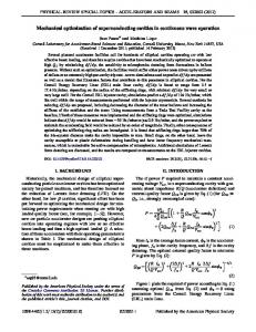
FIG. 1. (Color) Physical aperture and beam envelope at 480p mm mrad. The thick lines correspond to the vacuum pipe. Top: arc aperture. The dashed line corresponds to dp兾p0 苷 1%. Bottom: injection straight section. The dashed line is the closed orbit given by the painting bumps for a full beam. On each plot, the upper half corresponds to the horizontal plane while the vertical plane is plotted as a negative value.
the vacuum pipe and the lattice functions. The maximum acceptance available is calculated for protons with uncoupled motion in the horizontal and vertical planes. For secondary halo, the particle motion is likely to be coupled because of isotropic scattering and because the oscillation occurs at high amplitudes. We calculate the minimum horizontal Ax and vertical Ay acceptance as well as the combined one Axy 苷 Ax 1 Ay . Dispersion is taken into account with a momentum deviation dp兾p0 苷 61% corresponding to the bucket acceptance. Results of the acceptance calculations are shown in Table I. For a momentum deviation of 61%, the minimum acceptance is found in the center of the arc dipole where the dispersion hx and betatron amplitude by have an absolute and local maximum, respectively. The minimum acceptance value (around 520p) is still over the secondary halo maximum extent allowing a clean removal of the halo. For momentum cleaning, we require a momentum acceptance of dp兾p0 苷 62% to allow the off-bucket beam to drift between bunches. This condition is easily satisfied
TABLE I. Minimum aperture around the ring for the main quadrupole and dipole magnets. In the first three columns, the acceptance is calculated for the uncoupled painted beam where ex and ey are independent. For the secondary halo, we assume a coupled beam. Units are in p mm mrad.
Ax Ax Ax y
010101-2
dp兾p0 苷 0
Painted beam dp兾p0 苷 60.01
dp兾p0 苷 60.02
795.6 713.8 ···
640.5 680.0 ···
219 541 ···
Secondary halo dp兾p0 苷 0 dp兾p0 苷 60.01 795.6 713.8 684.6
640.5 680.0 522.7
010101-2
PRST-AB 4
OPTIMIZATION OF THE COLLIMATION SYSTEM FOR …
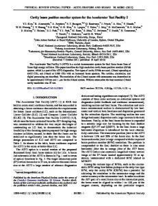
along the straight sections. In the arc, the minimum acceptance for this momentum deviation is 220p mm mrad, still larger than the beam total emittance 160p mm mrad. For the other apertures in the machine, such as injection and extraction kickers, rf ferrites, vacuum pipes, bellows, etc., we require a minimum acceptance of 480p mm mrad based on the actual lattice functions at every position. The final acceptance is checked following the detailed sequence of elements for every section of the ring. Figure 1 shows the beam envelope at 480p mm mrad and the vacuum pipe profile in the horizontal and vertical planes for the ring arc and for the injection straight section. The beam easily clears the vacuum pipe even in high dispersion regions with a momentum deviation of 61%. In the injection region, the aperture limitations are at the chicane magnets used for painting. At this location, the beam has a closed orbit bump in the vertical plane of 46 mm. B. Lattice With an infinite (or large enough) pipe radius for housing the halo, the final efficiency is determined by the lattice and space available for collimators, in particular, by the relative phase advance between primary and secondary collimators. In most machines, the lattice is already fixed when designing the collimation system. In the most fortunate cases, we have a machine section dedicated to collimation where we tailor the lattice to optimize phase advances, dispersion, and, ultimately, the collimation efficiency. In the case of the SNS ring, one straight section is dedicated to betatron cleaning with enough phase advance for locating the collimators. The lattice functions are common to all the machines and cannot be modified inside the cleaning section. Nevertheless, the design of the lattice has been done taking into account the collimation requirements. As an example, the previous version of the lattice for the SNS ring consisted of FODO cells both in the arcs and in the straight sections [11]. The fixed phase advance between available drifts was around 90±. The space available to locate the collimators was limited to four 5.2 m long half-cells. These two factors did not allow any optimization of the collimation system as the collimators had to be installed close to the center of each drift. That fixed the phase advance between collimators to 90±, far from the optimum values. The present lattice for the accumulator ring is a hybrid lattice consisting of FODO cells in the arc and doublet cells in the straight sections [6]. The total phase advance per straight section is 180± along 30 m, and the straight section is divided into three available drifts (6.85, 12.5, and 6.85 m, respectively) where long pieces of hardware as the collimators are easily accommodated. The Twiss functions along one of the four superperiods are shown in Fig. 2. Another convenient feature of the lattice is that the beta functions and phase advances in the x and y planes run 010101-3
Hybrid Lattice
010101 (2001) BETX
BETY
DX
25 20 15 10 5 0 0
10
20
30
s(m)
40
50
FIG. 2. (Color) Lattice functions along a ring superperiod. The doublet structure allows for long uninterrupted straight sections. Collimator locations are indicated by the arrows.
almost parallel within the straight section. Thus, a location with optimal phase advance between the primary and secondary collimators in the horizontal direction also has an optimal phase advance in the vertical direction. The total system is optimized with a smaller number of long collimators, namely, one primary and two secondary collimators. For a system whose primary and secondary collimators’ normalized aperture is n1 苷 2.1 and n2 苷 2.9 of the rms beam size, the optimum phase advance in the onedimensional case is mopt 苷 arccosn2 兾n1 艐 43± and its complement 137± [9]. For the collimation system of the SNS ring with one primary and two secondary collimators, the final phase advances were found by numerical minimization of the residual halo. The first collimator is located at the middle of the first straight section where bx 苷 by . The first secondary collimator is located in the long straight section between both doublets. The middle point of the collimator has a phase advance from the primary of mx 苷 43±, my 苷 26±. The last secondary collimator is located in the third straight section just before the matching quadrupole and the arc. Its phase advance with respect to the primary is mx 苷 144±, my 苷 161±. If needed, a third secondary collimator can be located at a phase advance of mx 苷 54±, my 苷 42±. The halo cuts done by each collimator in normalized one-dimensional phase space are indicated in Fig. 3. As we see from the figure, the third secondary collimator
FIG. 3. (Color) Beam and collimators in normalized phase space. Secondary collimators cut the primary halo as it evolves following the phase advance.
010101-3
N. CATALAN-LASHERAS et al.
is unnecessary as it falls almost in the shadow of the other two. III. CHOICE OF THE HARDWARE The collimators designed for the ring and transfer lines of the SNS consist of a layered structure designed to capture the beam protons and any resulting radioactive isotopes within the structure of the collimator. The final structure, including external shielding, is about 2 m long and weighs more than 20 tons. The innermost layer of the collimator, where the beam interacts, constitutes also the vacuum pipe of the ring and it is made of inconel, about 1 cm thick. A more detailed description of these collimators can be found in Ref. [12]. The SNS accumulator ring painting scheme is designed to provide both correlated and anticorrelated painting, producing a square or round beam, respectively, with different emittance and beam size [7]. Likewise, the final extent and profile of the natural halo will not be known exactly until the commissioning of the machine and, even then, it is likely to change over the years of operation as the machine and lattice are upgraded. Closed orbit excursions, beta beating, or tune change also affect the effective aperture of the collimators and small corrections are usually needed to recover a good cleaning efficiency. But once the collimators described before are in place inside the machine they become the main aperture restriction. We can only change their aperture by redesigning and replacing the vacuum pipe into the ring (and probably also the collimator inner block). While that could be done during long maintenance shutdowns if absolutely necessary, changing the aperture as operation evolves would be impossible and small corrections of the aperture during operation are unimaginable. The collimator’s aperture has to be chosen carefully in order not to limit unnecessarily the normal operation of a high intensity proton ring. A special design consisting of a movable inner surface for the ring collimator was proposed [12]. It turned out to be highly expensive and the reliability of the mechanical systems after some high irradiation and heat deposition cannot be guaranteed. The solution is to substitute the primary, long collimator with a thin, movable scraper, while keeping the secondary collimators with their original design. Independent motors drive four collimator jaws with a thickness of about 1 cm along the beam. In that way, the positions of these primary targets are adjusted during the operation and the shape of the collimator is adapted to the actual beam profile. The scheme adopted is then one primary movable scraper and two secondary absorbers with fixed aperture. A. Primary scraper At 1 GeV, the energy lost in a thin scraper is not negligible when compared with the total energy of the beam. A 1 GeV proton traversing 1 cm of material may lose more than 2% of its initial energy for heavy materials such as 010101-4
010101 (2001)
tungsten [13]. After leaving the scraper, the proton may be outside the rf bucket or the longitudinal acceptance of the ring and be lost in high dispersion regions. On the other side, the scraper has to kick the halo particles enough to drive them into the secondary collimators with a large impact parameter. This angular kick is mainly produced by multiple Coulomb scattering (mCs), which also depends on the scraper material. The ideal scraper has to produce both small energy loss and large multiple Coulomb scattering deflection angle. Figure 4 shows the mean scattering angle for different materials where the thickness has been adjusted to have an average momentum loss of 1% for 1 GeV protons. The best choice is very thin scrapers made of heavy metals as tungsten or platinum. On the other hand, the neutrons produced in spallation reactions increase the dose on the downstream quadrupoles and this effect becomes more important for heavier elements. Shower simulation for tungsten, iridium, copper, and platinum are performed using LAHET [14]. The number of neutrons per proton produced in a thin target for different materials is shown in Table II. Other characteristics that contribute to the choice of scraper material and thickness include availability, radiation and heat damage, melting point, thermal conductivity, etc. Some of these magnitudes are also included in Table II. From the point of view of collimation efficiency, simulations with different materials have been done to compare the effect on the overall efficiency. Once the length of the scraper is adjusted to disturb minimally the energy of the escaping protons, the results for all materials indicate a higher efficiency for heavier materials, as expected. Considering all the data, our preferred choice between heavy elements is platinum because of its high melting point and thermal conductivity that allows the scraper to cool down before melting. Contrary to tungsten, the platinum oxide is equally resistant to high temperatures as the pure element. Kick angle @ dp/p0=0.01 2.5 Th
2.0 Scattering angle [mrad]
PRST-AB 4
Hf
Ir
Ta W
Pt
U
Pb
Sn
1.5
Mo Ge
Zr
Nb
Ti Fe Cu
1.0 Al Si
0.5
C Be
0.0 0
20
40
60
80
Atomic number (Z)
FIG. 4. (Color) Average scattering angle for different materials. The length of the target has been fitted so as to produce an ionization energy loss of 1% of the initial energy.
010101-4
PRST-AB 4
OPTIMIZATION OF THE COLLIMATION SYSTEM FOR …
010101 (2001)
TABLE II. Comparison of different scraper materials. The neutron production has been obtained by simulation taking a thin target with the correct thickness to produce dp兾p0 苷 20.01. Material
Density 共g兾cm3 兲
Rad length (cm)
Melting point (±C)
Length (cm)
Spal. neutrons n兾p
Cu W Ir Pt Th
8.96 19.3 22.6 21.45 11.72
15.30 0.35 0.29 0.31 0.52
1083 3410 2410 1772 1750
1.1 0.5 0.5 0.5 1.0
0.45 0.89 0.92 0.90 1.14
FIG. 5. (Color) Schematic view of the primary collimator. The longitudinal and transverse profiles of the vacuum pipe are shown. The structure surrounding the vacuum pipe is similar to that of Fig. 6.
The primary collimator is thus a movable scraper made of four platinum plates that are inserted in the beam independently. The range of motion is defined by the beam emittance and the secondary collimator acceptance. Four motors drive the scrapers independently into the beam. The support for each scraper is tapered longitudinally to minimize the impedance. The whole mechanism is housed in a structure similar to an absorber. Figure 5 shows a schematic view of the primary collimator. B. Secondary absorbers As mentioned before, secondary collimators are designed as self-shielding structures capable of containing the shower of secondary particles after the proton is absorbed [12]. Their inner zone consists of a layered structure of increasing blackness to protons in the direction of the beam, and shielded by iron in radial and axial directions. The inner structure consists of light water, a water cooled steel particle bed, a water cooled iron particle bed, and light water in a layered structure. In addition, a high
FIG. 6. (Color) View of the absorber structure.
010101-5
density iron shield is added around the absorbers. A longitudinal cut of this absorber is shown in Fig. 6. Both secondary collimators have a fixed aperture of 300p mm mrad. They have an elliptical aperture matching the beta functions at the middle of the structure. The interface with the vacuum pipe is tapered to avoid excessive impedance contribution. Based on the results of a recent experiment in the BNL Tandem [15], a serrated, coated surface may be used to minimize secondary electron emission in the collimator surface. C. Collimator aperture We mentioned that the SNS accumulator ring is designed for correlated and anticorrelated painting. In the case of correlated painting, the final shape of the beam is square with maximum emittance ecor 苷 120p mm mrad in both horizontal and vertical planes. For anticorrelated painting, the final shape of the beam in the x-y plane is a circle with a maximum emittance of eant 苷 160p mm mrad. To accommodate the beam we need a primary aperture e1 $ e for both correlated and anticorrelated painting. To prevent primary impacts in the secondary collimators, e2 has to be larger than e1,ant in the anticorrelated case and larger than 2e1,cor for correlated painting. A schematic view of both scenarios is shown in Fig. 7. With e1,cor 苷 140p mm mrad and e1,ant 苷 180p mm mrad, the minimum secondary aperture is e2 苷 280p mm mrad. We
FIG. 7. (Color) Schematic view of the beam, pipe, and collimators in the real space x-y. For both cases, correlated and anticorrelated paintings are accommodated by adjusting the four scrapers of the primary collimator.
010101-5
PRST-AB 4
N. CATALAN-LASHERAS et al.
Kicker
Primary collimator
010101 (2001)
IV. EFFICIENCY CALCULATIONS A. Beam halo simulation
Beam
Gap beam 90 degrees
FIG. 8. (Color) Schematic view of the beam-in-gap (BIG) cleaner. The beam circulating between bunches is coherently kicked and drifts towards the vacuum pipe. In a small number of turns (10 – 20) it hits the scraper that acts as the main aperture restriction in the ring.
chose a value of 300p mm mrad to allow for flexibility in the positioning of the scrapers without compromising the efficiency (see Sec. V). D. Beam in gap cleaner Various mechanisms, including chopper inefficiency and energy straggling in the injection foil, produce a residual beam outside the rf acceptance. Protons lying outside of the rf bucket drift in longitudinal space and occupy the gap between bunches. This “beam in the gap” is lost during extraction, increasing the level of uncontrolled loss. As the space in the arcs is limited and the straight sections are dispersion free, there is no space in the ring to provide a dedicated momentum cleaning section using conventional collimators. A solution is to install a fast rise kicker in the line that fires between bunch passages [16]. The kicker drives the protons to the collimation system in several turns (typically 10–20), as illustrated in Fig. 8. The final absorption efficiency of these protons in the collimators is at least as high as for betatron losses. In practice, the cleaning efficiency is even larger because of the large impact parameter. This principle has already been experimentally demonstrated in the National Synchrotron Light Source at Brookhaven [17]. The kick has to be optimized to be as fast as possible keeping the kicked beam inside the ring acceptance. The final specifications of this beam-in-gap (BIG) cleaner are currently being studied. E. Collimation system layout The system consisting of one primary scraper and two secondary absorbers is located in the second straight section of the ring. The final layout of this line is shown in Fig. 9. The beam-in-gap kicker is located right after the extraction system.
Using the collimation system described in the previous section, we estimate the collimation efficiency using the K2 code, developed at CERN [18]. In this code, protons are given initial conditions inside the pipe, very close to the primary collimator aperture for saving computing time. At each new turn, the proton radial amplitude is increased in small steps according to an input drift velocity. That leads to a uniform distribution of impinging protons in the collimator surface with relatively small impact parameters. In the absence of very strong nonlinearities, this model represents any slowly growing halo, independently of the specific mechanism originating the halo. For tracking the protons inside the collimator, we use a Monte Carlo subroutine that simulates ionization energy loss, multiple Coulomb scattering (mCs), and nuclear elastic and nuclear inelastic interactions according to the collimator material. If undergoing an inelastic interaction, the particle is assumed to be absorbed by the jaw and the tracking is stopped without tracking secondary particles. If the proton leaves the collimator block without being absorbed, it is transported around the machine using a linear matrix according to the central tune. Special checks are performed to control the amplitude and momentum of the particles at generic places. This simple approach allows the tracking of a significant number of protons in a short time and provides high statistics. The coordinates at the absorption location are written by K2 in an ASCII file. This data can be fed into any Monte Carlo code calculating secondary particles and spallation products to estimate the radiation levels in the collimators and other components and calculate the necessary amount of shielding. One of the most relevant pieces of information obtained by simulation is the survival plot of the halo particles after collimation. It shows the number of initial protons exiting the collimation system above a certain aperture. This check is performed only once per proton, after the particle first touches the primary collimator. If the proton leaves the collimation system with an amplitude larger than the acceptance of the ring, we assume that it is lost around the ring before one turn, becoming uncontrolled loss. The inefficiency of the cleaning system (1 2 h) is defined as the fraction of the halo escaping the collimation system with an emittance equal to or larger than the ring acceptance.
FIG. 9. (Color) Layout of the collimator straight section.
010101-6
010101-6
OPTIMIZATION OF THE COLLIMATION SYSTEM FOR …
0.5 Correl Anti_cor
Inefficiency
0.4 0.3 SNS ring acceptance
0.2 0.1 0 300
350
400 450 500 Ring acceptance [ π µm]
550
600
FIG. 10. (Color) Integrated profile of the residual halo after traversing the collimation system. For a ring acceptance of 480p mm mrad, the inefficiency is about 5% for the correlated case and 7% for the anticorrelated.
B. Efficiency Figure 10 shows the survival plot for the actual base line design of the collimation system of the SNS ring. Both correlated and anticorrelated painting and cleaning schemes are presented. We obtain efficiencies larger than 90% for both nominal cases using two scrapers at e1 苷 140p mm mrad or four scrapers at e1 苷 180p mm mrad. The efficiency figures in both cases are 95% and 93%, respectively. On the other hand, tracking performed in the presence of space charge during the accumulation time indicates halo growth at the level of 1 2 3 103 of the total beam. We can achieve a cleaning efficiency of 95%, which means that a maximum of 1024 of the total beam will become uncontrolled loss. Assuming an homogeneous residual halo, losses will be distributed evenly around the machine and the final uncontrolled loss rate is about 1 nA兾m. More detailed analysis of the multiturn data is done to determine the final multiturn efficiency of the system and to identify potential hot points around the ring. V. RELIABILITY OF THE COLLIMATION SYSTEM In the previous section, we showed that the actual collimation system reaches the efficiency levels required for hands-on maintenance of the machine. Yet, we should check the robustness of the system against realistic deviations of the nominal conditions that would certainly take place during operation. A. Closed orbit and misalignments Because of the length of the collimators, alignment errors are expected to be very small and do not directly affect the final cleaning efficiency. Concerning closed orbit deviations, the minimum difference in aperture between primary and secondary collimators is determined to make sure that no halo particles suffer a primary impact in a secondary collimator. Assuming a maximum closed orbit 010101-7
010101 (2001)
deviation in the collimation section of 61 mm, a minimum difference n2 2 n1 between primary and secondary collimators is needed where ni is the number of given rms beam size (s). For the SNS accumulator ring, the rms beam size is of the order of centimeters. The difference in aperture between primary and secondary collimators has to be larger than 0.1s to prevent the secondary collimators from receiving a primary impact. For the nominal case, n2 2 n1 苷 0.8. B. Tunability As mentioned in Ref. [6], the SNS accumulator ring is designed to operate at least at three different working points. The cleaning efficiency should not be dramatically affected by the choice of tune because most of the tuning is done in the arcs while the phase advance is kept the same along the collimation straight section. Small differences may occur from the fact that changing the tune changes the beta function at the fixed absorbers and thus the normalized aperture e2 . Indeed, the residual halo profile shown in Fig. 11 for the three tune values does not present major differences. Especially in the region 400 500p mm mrad where the ring aperture lies, the difference in efficiencies does not exceed 1% of the initial halo. C. Halo drift velocity The impact parameter in the collimator determines the probability of outscattering of the proton and depends strongly on the drift velocity of the halo particles [19,20]. This drift speed is given by the halo formation mechanisms and nonlinear behavior of the machine. At the present time, we do not have accurate estimates or measurements of the drift velocity for the SNS ring halo. According to measurements performed in the superproton synchrotron machine at CERN, the K2 code assumes a linear variation of the drift velocity with the particle emittance [21]. By changing the slope of the linear function, we study how the final cleaning efficiency depends on the halo drift velocity. The drift velocity is given in units of s (rms beam size) per second. 1 225
Inefficiency
PRST-AB 4
325
425
525
625
725
6.30 -5.80 0.1
5.82 -4.80 5.82 - 5.80
0.01
Ring acceptance [ π µm]
FIG. 11. (Color) Residual halo profile for three different working points. The nominal tune is presented on the top curve (anticorrelated painting only).
010101-7
N. CATALAN-LASHERAS et al. Sec(1)
5
425
525
625
725
825
Inefficiency
d_0.5 d_1.0 d_5.0 d_10 d_50 d_100
0.1
4 3 2 1 0
QHB10 QVB11
325
Prim
225
10-4 fractional loss
1.0
Sec(2) QVC01 arc
Ring acceptance [π µm]
010101 (2001)
QVB12 QHB13
PRST-AB 4
[~ 1m]
FIG. 12. (Color) Cleaning efficiency as a function of the halo drift velocity. Velocity is given in s兾m where s is the rms transverse beam size.
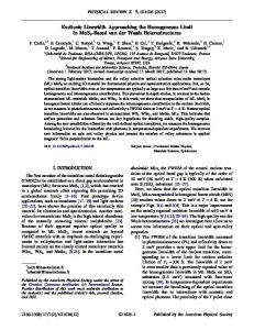
FIG. 14. (Color) Loss distribution along the collimation straight section. Each bin is approximately 1 m long. Losses in the collimators correspond to controlled loss and are plotted in blue. The quadrupole QHV10 right after the primary scraper receives an unacceptably high loss. As a result, the design of the primary scraper has been reviewed.
Figure 12 shows how the efficiency of collimation changes when the drift velocity and, thus, the impact parameter are changed. Changes of the impact parameter across 3 orders of magnitude had no significant affect in the final profile of the survival halo or in the cleaning efficiency. This result is explained by the fact that two-stage collimator systems are designed to catch most backscattering particles. They are then less sensible to impact parameter variations.
for both collimation schemes. We see from the plot that the nominal efficiency is better for correlated painting, but it deteriorates faster with increasing e1 as the secondary collimator becomes partially a primary collimator. Keeping the final cleaning efficiency above 90%, we can open the primary collimator up to 205p mm mrad for a square beam and up to 180p mm mrad for a round beam.
0.0
VI. LOSS DISTRIBUTION D. Primary aperture In the one-dimensional case, the difference between primary and secondary acceptance e1 and e2 defines the optimum phase advancepbetween collimators (fopt 苷 arctann2 兾n1 ), where n 苷 e兾erms [9]. In two dimensions, the optimization of the system is made numerically using fixed values for the acceptance. The location of the secondary collimators is optimized for collimator acceptance e2 苷 300p mm mrad and e1 苷 140 180p mm mrad for correlated and anticorrelated painting, respectively. Still, in the eventuality of a different beam size, we should be able to retract the primary scrapers without a significant decrease in the cleaning efficiency. Figure 13 shows the cleaning efficiency when the primary collimator is moved from its nominal position and
Inefficiency
0.1
Correlated
Anti-correlated
We estimate the distribution of losses along the cleaning section. To probe losses, we distribute completely absorbent collimators within every meter of free drift with an aperture equivalent to the vacuum pipe. We also place collimators at the entrance of each quadrupole. The results of the simulation are shown in Fig. 14. Based on these results, the structure around the scraper has been redesigned and shielding has been added before the QHB10 magnet. An estimate of the residual radiation coming from these losses is presented in Ref. [22]. We also foresee losses from the injection process. H 2 ions missing the foil and partially stripped H 0 particles may be as large as 10% of the beam. This loss is, however, controlled loss, as specific shielding and dump lines are designed to manage the scattered beams. Uncontrolled losses such as H 2 stripping in the injection magnet and nuclear scattering in the foil account for a fractional loss of 1 3 1025 [23]. The final uncontrolled fraction loss is under 1024 , distributed homogeneously around the ring. Slightly higher losses are expected at the injection and extraction regions where the acceptance is minimum. Further work is in progress to determine the loss pattern around the ring depending on collimation aperture and halo growth rate.
0 130
150
170 190 Primary Acceptance [ π µm]
210
FIG. 13. (Color) Cleaning efficiency as a function of the primary aperture for both cases, correlated and anticorrelated painting. Secondary collimators are fixed at 300p mm mrad.
010101-8
VII. CONCLUSIONS A collimation scheme including transverse and longitudinal cleaning has been designed for the SNS accumulator ring. The system is composed of a primary collimator with 010101-8
PRST-AB 4
OPTIMIZATION OF THE COLLIMATION SYSTEM FOR …
four movable scrapers, two secondary collimators working as absorbers, and a fast beam-in-gap kicker for longitudinal cleaning of the beam. The shape, aperture, and material of the hardware components have been chosen taking into account efficiency calculations as well as reliability. The final system reaches the efficiency levels demanded for hands-on maintenance and is highly reliable, working at high efficiency away from the nominal conditions. Work has to be pursued in parallel with the ongoing design, construction, and installment of components in the ring to tabulate the acceptance of every element in the machine and identify bottlenecks and hot spots. A more detailed description of the collimation section including magnet apertures, shielding, and variable shape collimators is being implemented into the simulation codes to give more accurate predictions. Also, the codes used for simulation are being benchmarked with real measurements at 1–1.3 GeV [24]. ACKNOWLEDGMENTS The authors would like to thank D. Kaltchev, J. B. Jeanneret, G. Rees H. Schonauer, and C. Warsop for their priceless advice. Special thanks to W. T. Weng for his encouragement and support. The work presented in this paper has been supported by the U.S. Department of Energy.
[1] The NSNS Collaboration, Oak Ridge National Laboratory Technical Report No. NSNS/CDR-2, 1997. [2] N. Catalan-Lasheras et al., in Proceedings of the 7th ICFA Mini-Workshop on High Intensity High Brightness Hadron Beams, Lake Como, Wisconsin, 1999, edited by N. Mokhov and W. Chou (Fermi National Laboratory, Batavia, IL, 1999).
010101-9
010101 (2001)
[3] R. J. Macek, in Workshop on Space Charge Physics in High Intensity Hadron Rings, edited by A. U. Luccio and W. T. Weng, AIP Conf. Proc. No. 448 (AIP, New York, 1998). [4] Y. Y. Lee, D. Raparia, and J. Alessi, BNL /SNS Technical Report No. 065, 1999. [5] D. Raparia et al., BNL /SNS Technical Report No. 006, 1996. [6] J. Wei et al., Phys. Rev. ST Accel. Beams 3, 080101 (2000). [7] J. Beebe-Wang et al., in Proceedings of the 7th European Particle Accelerator Conference, Vienna, 2000, http: //accelconf.web.cern.ch /AccelConf /e00 /index.html [8] J. B. Jeanneret and T. Trenkler, Part. Accel. 50, 287– 311 (1995). [9] J. B. Jeanneret, Phys. Rev. ST Accel. Beams 1, 081001 (1998). [10] D. Kaltchev, TRIUMF Report No. TRI-DN-99-16, 1999 [11] J. Wei et al., in Proceedings of the 1999 Particle Accelerator Conference, New York (IEEE, Piscataway, NJ, 1999). [12] H. Ludewig et al., in Proceedings of the 1999 Particle Accelerator Conference, New York (Ref. [11]). [13] D. E. Groom et al., Eur. Phys. J. C 15, 1 (2000). [14] H. Lichtenstein and R. E. Prael, Los Alamos National Laboratory Report No. LA-UR-89-3014, 1989. [15] P. Thieberger et al., BNL /SNS Technical Report No. 064, 1999. [16] R. Witkover, BNL/SNS Technical Report No. 49, 1998. [17] D. P. Siddons, R. J. Nawrocky, and U. Bergmann, in Proceedings of the 1993 Particle Accelerator Conference, Washington, DC (IEEE, Piscataway, NJ, 1993). [18] J. B. Jeanneret and T. Trenkler, CERN SL Note No. 94105(AP), 1994. [19] T. Risselada CERN SL/Note No. 92-16AP, 1992. [20] M. Seidel, DESY Report No. 94-103, 1994. [21] J. B. Jeanneret, L. Burnod, and G. Ferioli, CERN LHC Technical Report No. CERN/SL/90-01 (EA), 1991. [22] H. Ludewig et al., in Proceedings of the 7th European Particle Accelerator Conference, Vienna, 2000 (Ref. [7]). [23] D. Raparia, BNL /SNS Technical Report No. 058, 1999. [24] N. Catalan-Lasheras et al., in Proceedings of the 7th European Particle Accelerator Conference, Vienna, 2000 (Ref. [7]).
010101-9