2004 IEEE Ultrasonics Symposium
OPTIMIZED MEMBRANE CONFIGURATION IMPROVES CMUT PERFORMANCE Yongli Huang, Edward O. Hæggström, Xuefeng Zhuang, Arif S. Ergun, and Butrus T. Khuri-Yakub Edward L. Ginzton Laboratory, Stanford University, Stanford, CA 94305-4088 Email:
[email protected]
membranes, as well as membranes with arbitrary thickness profiles. Hence, wafer bonding provides design flexibility in both the horizontal and vertical dimensions. Because the device yield associated with this technique does not strongly depend on membrane configuration or device dimension, the fabrication no longer restricts efforts to optimize the membrane configuration to improve CMUT performance.
Abstract— The performance of a capacitive micromachined ultrasonic transducer (CMUT) was improved by optimizing its membrane configuration. CMUTs with three different membrane configurations: square, rectangular and tent, were designed and fabricated using a process based on the wafer-bonding technique. Paired tests showed that improved transmission (TX) and reception (RX) efficiencies were achieved by using tent or rectangular membranes instead of square membranes. The improvements were 46% and 44% in TX and 43% and 65% in RX, respectively.
This paper concentrates on the horizontal design optimization, and reports on relative CMUT performance achieved by three membrane configurations: square, rectangular and tent. The experimental results show that membrane configuration optimization improves the device performance for both transmission (TX) and reception (RX).
Keywords- CMUT; Optimization; Rectangular; Tent
I. INTRODUCTION CMUTs have been fabricated and tested for more than a decade [1,2,3] and compete with piezo-based ultrasonic transducers for use in applications such as medical imaging. Two common criteria used for evaluating transducers are bandwidth and transmission/reception efficiency. CMUTs usually have a wider bandwidth, but lower transmission/reception efficiency (TRE) [4] than piezo-based ultrasonic transducers. Efforts have been made to improve their transmission/reception efficiency, including the recently reported method of operating them in the collapsed region [5]. This approach greatly improves their TRE, but at the cost of increased hysteresis (dependence of capacitance on current bias voltage and bias voltage history) [6].
II. DEVICE DESIGN, FABRICATION AND CHARACTERIZATION
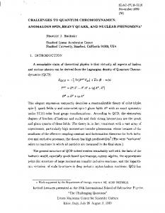
The basic structure of a CMUT is a parallelplate capacitor with a rigid bottom electrode, and a top electrode residing on or within a movable plate. The movable plate is used to transmit or detect an acoustic wave in the adjacent medium [1]. Fig. 1 shows crosssections of ideal (as piston-like as possible) and non-ideal CMUT cells. The design optimization aims to maximize both the average membrane displacement for a given received pressure (reception efficiency) and the average output pressure for a given applied operation voltage during transmission (transmission efficiency). Ideally, the top electrode should be flat during operation and have a uniform displacement across the whole membrane in order to produce maximum output power and reception sensitivity. Because neither the deflection nor the displacement of a flexible CMUT membrane fixed along its edges is uniform under pressure loading, the performance of a CMUT featuring a fixed element size and a certain operation
Most CMUT designs reported to date carry circular, hexagonal or square shaped cells [1,2,3]. Since these CMUTs were surface micromachined [1,2], the choice of configurations was probably dictated by device fabrication considerations, e.g., sacrificial layer etch and membrane internal stress. Using a process based on the wafer-bonding technique [3], it is possible to fabricate CMUTs with different configurations of uniform-thickness
0-7803-8412-1/04/$20.00 (c)2004 IEEE.
505
2004 IEEE International Ultrasonics, Ferroelectrics, and Frequency Control Joint 50th Anniversary Conference
2004 IEEE Ultrasonics Symposium
frequency can be improved by an optimized membrane design. The improvement stems from three factors: 1) an increased average membrane displacement for a given pressure loading; 2) an increased average electrostatic pressure for a given operation voltage and gap; and 3) an increased fill factor and a reduced parasitic capacitance.
a)
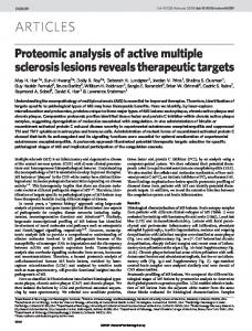
deflection, since both the electrostatic pressure and capacitance change depend on the inverse gap squared. Fig. 2 shows comparisons between average electrostatic pressure and capacitance change for the three CMUT configurations as a function of cavity gap. Static simulation cannot provide the exact amount of improvement of the designs because both TX and RX test results also depend on other factors such as the electrical impedance match between the device and input source and the parasitic capacitance of the device etc. However, static simulation does provide qualitative guidance to device optimization.
b)
Figure 1. Cross-sectional view of a) a non-ideal CMUT cell, b) an ideal CMUT cell.
Since both the estimated performance difference (extrapolated from the membrane deflection and membrane shape) and the fill factor between CMUTs carrying square, circular, or hexagonal configuration membranes were relatively small, a square CMUT with 90 µm by 90 µm membranes was selected to represent the conventional membrane design. A rectangular CMUT with 73 µm by 540 µm rectangular membranes, and a tent CMUT with 540 µm by 540 µm tent membranes rigidly anchored to 14 µm square support posts (70 µm pitch), were designed for comparison. The membrane designs were chosen in such a way that all CMUTs worked in the same 2 MHz frequency region. All membranes were made from 1 µm thick single-crystal silicon; the support walls in the square CMUT and rectangular CMUT were 5 µm wide.
Table 1. Calculated parameters for the three CMUT designs.
Flatness Disp.(nm/Pa) Fill Factor
Square .30 1.2 89%
Rect. .46 1.6 93%
Tent .52 1.9 95%
1.7
2
Electrostatic Pressure Ratio
1.6
1.9
1.5
1.8
1.4
1.7
1.3
1.6
1.2
1.5
1.1 0.2
0.3
0.4
0.5
0.6
0.7
0.8
0.9
Capacitance Change Ratio ( per Pa)
Rectangular/Square (Pressure) Tent/Square (Pressure) Rectangular/Square (Capacitance) Tent/Square (Capacitance)
1.4 1
Gap (µm)
ANSYS simulations were used to predict the performance of the CMUTs[6]. Table 1 lists the estimated device flatness, average static displacement (Disp.), and fill factor of the square, rectangular and tent membrane designs. The device flatness is defined as the average static membrane deflection at the operation point relative to the maximum membrane deflection. The average static displacement is the average membrane displacement change caused by a 1 Pa pressure change when the device is in atmospheric conditions. The cavity gap is defined as the shortest distance between the membrane and the bottom electrode.
Figure 2. Simulation results of electrostatic pressure ratio and static capacitance change ratio per Pa between rectangular and square CMUT, and between tent and square CMUT as a function of the gap.
The CMUTs were fabricated using a waferbonding technique as detailed in [3]. Fig. 3 shows 3D profiles of a finished device obtained with a Wyko surface profiler. The ultrasonic characteristics of the CMUTs were measured by broadband pitch-catch and pulse-echo tests in vegetable oil. In the TX measurements, the distance between the hydrophone and the CMUT transmitter was 13.7 mm (Seki parameter=1.6); a 10 Vp-p, 2.5 MHz, 30 cycle sinusoidal wave train was applied to the CMUT. The hydrophone (PZT-Z44-0400, SEA) was
The amount of performance improvement is a strong function of both gap and maximum
0-7803-8412-1/04/$20.00 (c)2004 IEEE.
506
2004 IEEE International Ultrasonics, Ferroelectrics, and Frequency Control Joint 50th Anniversary Conference
2004 IEEE Ultrasonics Symposium
positioned by an Aerotech HDZ2 linear translation stage, with 1 µm accuracy. Before it was read into the oscilloscope, the signal from the hydrophone was amplified by a 20 dB, 0.1400 MHz, 50 Ω pre-amplifier (HP8447A). The transducers were aligned so that a maximum reception voltage was obtained. In the RX measurements, the distance between the hydrophone and the CMUT was 86 mm; a 2.5 MHz, 10 Vp-p 30 cycle sinusoidal wave train was applied to a transmitting 12.5 mm diameter Panametrics V109 circular flat-focus transducer. Prior to the RX tests, a reception calibration experiment was carried out to calculate the sensitivity of the CMUT. In this test, the CMUT was replaced by the hydrophone in order to determine the acoustic pressure generated by the PZT onto the CMUT surface.
However, a quantitative comparison between the devices for all bias voltage points cannot be made without experimental data on membrane deflection versus bias voltage for a device operating in oil. The data at 20 VDC was chosen as an example, since this voltage is both small enough to ensure a membrane deflection very similar to the static deflection at atmospheric pressure, and large enough to obtain a clearly discernible signal. At 20 VDC, the output pressure per input voltage in TX was, on average, 46% and 44% higher for the rectangular CMUT and the tent CMUT, respectively, in comparison with the square CMUT. At 20 VDC, the average sensitivity in RX was 43% and 65% higher for the rectangular CMUT and the tent CMUT, respectively, than for the square CMUT. The TX and RX spectra of the designs were slightly different for the three configurations, but had a similar uncorrected fractional bandwidth (~ 135%). In TX, at a bias right before collapse, we obtained 3.82 kPa/VAC at 75VDC with the rectangular CMUT, 4.16 kPa/VAC at 90 VDC with the tent CMUT and 2.86 kPa/VAC at 85 VDC with the square CMUT. Normalized by the collapse voltage, the optimized designs improved TX efficiency by 50% and 37% over a square CMUT, thus verifying the performance improvement in both TX and RX predicted by the simulations.
To ensure a fair comparison, the experimental TX and RX results were normalized by the maximum electric field intensity in the CMUT cavity gap. In both TX and RX, the rectangular CMUT and tent CMUT showed a higher transmission and reception efficiency through the entire bias range than the square CMUT. As expected, the performance improvement gained by the new membrane configuration designs varied with bias. The simulations had predicted that the performance improvement would be a strong function of the cavity gap. a)
b)
c)
50 µm
500 µm
500 µm
Figure 3. 3D profiles of square, rectangular and tent CMUTs ( by Wyko Profiler) 0.6
VDC=60 V
11
b)
VDC=60 V
1
c)
VDC DC=60 V
0.5 0.5
0
-0.2 -0.4
Amplitude (mV)
0.2
Amplitude (mV)
Amplitude (mV)
2
a)
0.4
0
-1
-2
00 -0.5 -0.5 -1 -1
-0.6 -1.5 -1.5
-3
-0.8
-1 7
8
9
Time(µs)
10
11
-4 7
8
9
Time (µs)
10
11
-2 -2 88
99
10 10
Time(µµs) s) Time(
11 11
12 12
Figure 4. Transmission pulse of CMUTs with a) square, b) rectangular and c) tent membranes, obtained by a hydrophone. The input is a 5 V step function.
0-7803-8412-1/04/$20.00 (c)2004 IEEE.
507
2004 IEEE International Ultrasonics, Ferroelectrics, and Frequency Control Joint 50th Anniversary Conference
2004 IEEE Ultrasonics Symposium
a)
3
VDC=60 V
VDC=60 V
4
1
Amplitude (mV)
0
-2
0
-1
-2
-3
-4
-6 55
b)
c)
60VDC VDC=60 V
2
2
Amplitude (mV)
Amplitude (mV)
4
6
4
6
2 0 -2
-4
-4 56
57
58
Time (µs)
59
60
-5 55
56
57
58
Time(µs)
59
60
-6 55
56
57
58
Time (µs)
59
60
Figure 5. Reception pulses by CMUTs with a) square, b) rectangular and c) tent membranes. The transmitter was a PZT transducer with a 10 V step function input.
IV. ACKNOWLEDGEMENT
Since the optimized devices carried fewer (56 for the rectangular CMUT and 8 for the tent CMUT) sub-cells with independent cavities than the square devices (288 sub-cells), the optimized CMUT yield is potentially more sensitive to fabrication-induced defects than the square device design. However, the process based on the wafer-bonding technique had higher yield than that of the surface micromachining technique. No difference in yield was observed between the three designs fabricated for this study.
The authors acknowledge Office of Naval Research and the National Institutes of Health for financial support. Dr. Hæggström acknowledges the Helsinki Institute of Physics and the Chancellor of the University of Helsinki for financial support.
V. REFERENCES [1] X. C. Jin, et al., “Fabrication and characterization of surface micromachined capacitive ultrasonic transducers,” J. Micro-electromech. Syst., 8, p. 100– 114, 1999. [2] P. Eccardt, et al., “Micromachined transducers in CMOS technology”, proc. Ultrason. Symp., 1996, p. 959–962. [3]Y. Huang, et al., “Fabricating capacitive micromachined ultrasonic transducers with waferbonding technology,” J. Micro-electromech. Syst., 12, 2003, p. 128- 137. [4] D. M. Mills, “Medical Imaging with Capacitive Micromachined Ultrasound Transducer (cMUT) Arrays,” Proc. 2004 IEEE Ultrason. Symp., Montréal, August 24-27, 2004. [5] B. Bayram, et al. "A New Regime for Operating Capacitive Micromachined Ultrasonic Transducers," IEEE Trans. UFFC, 50(9), p. 1184-1190, 2003. [6] Y. Huang, et al., “Comparison of Collapsed Region and Pre-collapse Region Operation CMUTs Built with Wafer Bonding Technique,” Proc. 2003 IEEE Ultrason. Symp., Hawaii, Oct. 6-9, 2003.
Figure 6. Uncorrected transmission spectrum of square, rectangular and tent CMUTs.
III. CONCLUSION CMUT performance in both transmission (TX) and reception (RX) can be improved by optimizing membrane configuration. The improvement depends on the gap and the membrane deflection at the operating point. The fabrication based on the wafer bonding technique achieved same yields for all three designs.
0-7803-8412-1/04/$20.00 (c)2004 IEEE.
508
2004 IEEE International Ultrasonics, Ferroelectrics, and Frequency Control Joint 50th Anniversary Conference