... location limitation is noted in the particular discussion. Figure 6. Schematic of typical vitrification treatment process. (Adapted from www.geomelt.com, 03/15/01 ...
OVERVIEW OF INNOVATIVE REMEDIATION APPROACHES FOR CHLORINATED SOLVENTS
Mark L. Brusseau1 Robert G. Arnold2 Wendell Ela2 James Field2 1
Department of Soil, Water, and Environmental Science, and Department of Hydrology and Water Resources, University of Arizona 2 Department of Chemical and Environmental Engineering, University of Arizona
Prepared for: Dr. David Esposito, Director Waste Programs Office Arizona Department of Environmental Quality
March 26, 2001
TABLE OF CONTENTS
Executive Summary………………………………………………………………….
2
Introduction………………………………………………………………………….
4
Background…………………………………………………………………………. Immiscible liquid dissolution……………………………………………….. Biodegradation processes…………………………………………………… Abiotic transformation reactions………………………………………….… Process parameters…………………………………………………………..
5 5 8 11 14
Enhanced Removal and Isolation Methods…………………………………………. Air sparging…………………………………………………………………. Enhanced solubilization/mobilization………………………………………. Thermal desorption…………………………………………………………. Steam extraction…………………………………………………………….. Electrokinetic processes……………………………………………………. . Isolation techniques………………………………………………………….
19 19 19 21 22 23 23
Abiotic Transformation Methods…………………………………………………… Chemical oxidation……….………………………………………………… Chemical reduction………………………………………………………….
26 27 31
Biotic Transformation Methods…………………………………………………….. Monitored natural attenuation…………………………………………….… Anaerobic in situ treatment…………………………………………………. Sequential anaerobic-aerobic in situ treatment……………………………… Aerobic in situ treatment……………………………………………………. Permeable bio-reactive barriers…………………………………………….. Above-ground treatment…………………………………………………….. Phytoremediation……………………………………………………………. Other technologies…………………………………………………………...
39 39 41 43 43 43 43 44 45
Site Characterization………………………………………………………………… Site characterization…………………………………………………………. Mathematical modeling………………………………………………………
45 45 50
Summary……………………………………………………………………………..
51
References……………………………………………………………………………
51
EXECUTIVE SUMMARY Groundwater pollution has become one of our most pervasive environmental problems, and remediating sites with contaminated groundwater has proven to be a formidable challenge. Remediation efforts are often limited by the complexity of the subsurface environment, and by our lack of knowledge of that environment. Recent research has focused on enhancing our understanding of the complex subsurface environment and on developing innovative technologies capable of addressing these complexities. The purpose of this report is to provide a brief overview of the status of hazardous waste site remediation, with a specific focus on the issues associated with chlorinated-solvent contaminated sites. Initial efforts to remediate groundwater contamination focused on pump-and-treat approaches (flushing water through the formation and treating the extracted fluids). This approach has proven to be generally successful for preventing further spread of contamination (plume containment). Unfortunately, it has been generally ineffective for restoring systems to "pristine" conditions. Numerous factors are responsible for the ineffectiveness of pump-and-treat remediation, with one of the most common being zones of high concentrations or large masses of contaminants (i.e., source zones). While pump and treat can effectively manage the dilute portion of the plume, contaminant mass removal from the source zones is usually limited by equilibrium (e.g., solubility) and kinetic (e.g., dissolution, desorption, diffusive mass transfer) related constraints. For example, as noted in a National Research Council report on groundwater remediation, the presence of immiscible-liquid (so-called NAPLS, or non-aqueous phase liquids) contamination in the subsurface is often the single most critical factor influencing remediation of sites contaminated by organic compounds. Successful remediation of many contaminated subsurface systems is dependent on the development and implementation of technologies that can control or remove source-zone contamination. If source zones are present, the associated groundwater contaminant plumes can not be remediated effectively unless the source zones are at least controlled. This can be accomplished in a number of ways. For example, physical barriers (e.g., slurry walls) can be used to isolate the source zone, thus shutting off the supply of contamination to the plume. Hydraulic controls can also be used, especially for deep or large source zones where physical barriers are impractical. The system will generally need to be managed "in perpetuity", which in itself may be costly. An alternative to source control is actually reducing the contaminant mass resident in the source zone. This can be accomplished by either increasing the mass removal rate, or by promoting in-situ chemical or biological transformation reactions. Many of the innovative technologies currently in development are focused on source-zone remediation. Injecting solutions containing chemical amendments that solubilize or mobilize NAPL and sorbed-phase contamination is one means by which to enhance pump-and-treat removal of organic contaminants. Chemical amendments include surfactants (detergents), complexing agents (sugars), and cosolvents (alcohols). The use of such amendments for enhanced removal of immiscible-liquid contamination has become a major focus of research and pilot-scale testing. Air sparging, which involves injecting air into the contaminated portion of the saturated zone, is another means by which to possibly enhance the rate of contaminant mass removal from groundwater. Electrokinetic processes, which depend on application of an electrical field to the contaminated zone, can be used both to enhance mass removal and, for certain species, to destroy contaminants in the subsurface. In many places, especially the southwest USA, source zones are associated with the vadose zone as well as the saturated zone. Soil venting (or soil vapor extraction) has become a
2
widely used method for removing volatile organic contaminants from contaminated vadose-zone systems. However, soil venting has been shown to suffer some of the same types of massremoval constraints as pump and treat. Current research is underway to examine methods by which to enhance the effectiveness of soil venting. Thermal desorption and steam injection are two such methods that are being tested for enhanced removal of organic contaminants from both vadose and saturated-zone systems. One possible constraint to the use of enhanced-removal technologies is the disposition of the potentially large volumes of waste brought to the surface. This question has helped generate research into the development of innovative aboveground waste treatment technologies. Such technologies under investigation include several based on abiotic and biotic transformation reactions for both aqueous and gas-phase systems. Promoting in-situ biotransformation of contaminants (in-situ bioremediation) is one method that has received enormous attention for waste-site remediation. In-situ bioremediation methods, based on anaerobic or aerobic biotransformation reactions, or a combination of both, are under investigation for sites contaminated by chlorinated solvents. In addition to active (e.g., engineered) in-situ bioremediation methods, monitored natural attenuation processes (of which intrinsic bioremediation is a significant component) have become a great interest, particularly for dealing with contaminant plumes. The promotion of in-situ chemical transformations (e.g., oxidative/reductive reactions) has just started to receive significant attention. Technologies under current investigation include passive methods such as permeable reactive barriers employing zero-valent iron filings, and active methods based on injecting oxidative solutions (permanganate, Fenton’s reagent, ozone) into the target area. Both chemical and biological transformation methods have the obvious potential advantage of destroying the contaminant in situ, obviating the need for aboveground treatment or disposal. Clearly, the selection, design, implementation, and evaluation of a remediation system can not be optimized without accurate and sufficient information for the physical, chemical, and biological properties of the subsurface, as well as relevant transport and fate processes. Currently, most sites are not characterized sufficiently due to cost and time constraints. The development of new site-characterization technologies will enhance the effectiveness of current remediation technologies and provide the basis for implementation of new innovative technologies. The use of mathematical modeling has become an increasingly important component of site characterization and remediation activities. As such, it is critical that models are developed and applied in such a manner to provide an accurate and site-specific representation of contaminant transport and fate. It is clear that employing advanced characterization and modeling efforts that are integrative and iterative in nature enhances the success of remediation projects. Many innovative technologies are currently under investigation, and may be amenable for use at WQARF sites. There is, however, an enormous gulf between the development of a technology and its widespread use in the field. The key question for any innovative technology is, will that technology work at the specific field site of interest? Clearly then, "proof of performance" is central to the acceptance and use of a technology. Definitive proof of performance can be obtained only from field tests conducted under controlled, well-characterized conditions. Such tests should form the basis for any technology demonstration program.
3
1. INTRODUCTION The contamination of groundwater by hazardous organic chemicals and the associated risks to human health and the environment have become issues of great importance. Tetrachloroethene (PCE) and trichloroethene (TCE) are among the most common groundwater contaminants in the USA due to their widespread use as dry-cleaning solvents and as degreasing agents for military and industrial applications. An overwhelming majority (93%) of the superfund sites in the State of Arizona are contaminated with PCE and TCE (Anonymous, 2000). For many of these sites, PCE or TCE was the sole initial contaminant, although less chlorinated ethenes, such as dichloroethenes (DCE) and vinyl chloride (VC), can be present as a result of biotransformation reactions. Initial efforts to remediate groundwater contamination focused on pump-and-treat approaches (flushing water through the formation and treating the extracted fluids). This approach has proven to be generally successful for preventing further spread of contamination (plume containment). Unfortunately, it has been generally ineffective for restoring systems to "pristine" conditions (NRC, 1994, 1997). Numerous factors are responsible for the ineffectiveness of pump-and-treat remediation, with one of the most common being the presence of zones of high concentrations or large masses of contaminants (i.e., source zones). While pump and treat can effectively manage the dilute portion of the plume, contaminant mass removal from the source zones is usually limited by equilibrium (e.g., solubility) and kinetic (e.g., dissolution, desorption, diffusive mass transfer) related constraints. Successful remediation of many contaminated subsurface systems is dependent on the development and implementation of technologies that can control or remove source-zone contamination. The heterogeneous nature of the subsurface is another major constraint to the successful cleanup of contaminated subsurface environments. Clearly, the selection, design, implementation, and evaluation of a remediation system can not be optimized without accurate and sufficient information on the physical, chemical, and biological properties of the subsurface. This includes characterizing (1) the magnitude and variability of important material properties (e.g., hydraulic conductivity, bacterial populations, pH), (2) the type, amount, and distribution of contaminants, and (3) the major contaminant transport and fate processes. Currently, most sites are not characterized sufficiently due to cost and time constraints. It is now recognized that the remediation technologies currently in widespread use (e.g., pump and treat, soil venting), can not solve all subsurface contamination problems. Furthermore, it is clear that traditional site characterization approaches are not sufficient to promote optimal design, implementation, and evaluation of remediation systems. This recognition has fueled the development of new, so-called "innovative" remediation and characterization technologies. Many of these innovative technologies are in fact not new at all. For example, surfactant flushing has a long history of use in the petroleum field. However, its use in the environmental field is more recent and faces unique challenges, hence its "innovative" status. In any event, new technologies continue to be developed, increasing our arsenal of potential tools available for subsurface characterization and remediation. The purpose of this report is to provide a brief overview of the status of hazardous waste site remediation, with a specific focus on the issues associated with chlorinated-solvent contaminated sites.
4
2. BACKGROUND The transport and fate behavior of chlorinated-solvent compounds is very complex, and is influenced by a number of processes as depicted in Figure 1. Significant processes of interest include advection, dispersion, sorption/desorption, dissolution, evaporation, volatilization, and abiotic and biotic transformation reactions. Three factors of particular importance for chlorinated solvents, and which have significant impact on remediation, are immiscible-liquid mass transfer processes, biotransformation processes, and abiotic transformation processes. These three sets of processes are reviewed in the following sections.
Figure 1. Schematic of chlorinated solvent pollution as dense non-aqueous phase liquids migrating downward in an aquifer and serving as a source for a solvent soluble plume. Also shown are natural attenuation processes (U.S. EPA 1999).
Immiscible Liquid Dissolution One of the most critical issues associated with hazardous waste sites is the potential presence of immiscible-liquid contamination in the subsurface. Immiscible liquids introduced into the subsurface become trapped in the pore spaces due to capillary forces (see Figure 1). Very large pore-water velocities (i.e., hydraulic gradients) are usually required to displace residual quantities of
5
immiscible liquids (cf., Wilson and Conrad, 1984; Willhite, 1986; Hunt et al., 1988). Hence, the primary means of removal will be dissolution into water (and evaporation into soil-gas for the vadose zone). The residual liquid, therefore, serves as a long-term source of contamination due to the relatively low water solubilities of typical NAPL contaminants. The behavior of NAPLs such as chlorinated solvents is further complicated by the fact that they are denser than water, which influences their transport, retention, and dissolution. In fact, according to the National Research Council, the presence of DNAPL is usually the single most important factor limiting the cleanup of organic-contaminated sites (NRC 1994). Thus, it is clear that accurate risk assessments, as well as the design and implementation of effective remediation systems require an understanding of NAPL behavior in the subsurface. Some of the major factors affecting dissolution of NAPLs in the subsurface are discussed below. While the focus of the discussion will be on dissolution processes, most of these issues are applicable to immiscible-liquid evaporation as well. NAPL Dissolution: Equilibrium and Rate-Limited Behavior A majority of the immiscible-liquid dissolution literature is focused on dissolution of uniform distributions of immiscible liquid from columns packed with homogeneous porous media. This research has contributed significantly to our understanding of local-scale dissolution processes (i.e., pore-scale mass transfer). The results of this research indicate that Immiscibleliquid dissolution at the field scale should behave as an equilibrium process under the residence times associated with typical field systems. However, field data frequently show that groundwater concentrations of NAPL constituents are well below their respective aqueous solubilities (Mackay and Cherry, 1989; Mercer and Cohen, 1990). This apparent dichotomy is a result of the fact that there are several factors, in addition to local-scale mass transfer, that can influence immiscibleliquid dissolution at the field scale. These factors may often cause aqueous concentrations to be significantly less than equilibrium levels, thereby producing what may appear to be rate-limited behavior. Such behavior may often be due to limited contact between advecting water and the immiscible liquid. For example, a non-uniform distribution of immiscible liquid may lead to a bypass flow effect, wherein water flows primarily around a zone of relatively high immiscibleliquid saturation (e.g., pools) due to the reduced relative permeability associated with the zone. Immiscible liquid may under certain conditions be trapped within lower intrinsic-permeability zones, wherein the preferential flow associated with the presence of higher-permeability zones adjacent to lower-permeability zones may greatly limit contact between advecting water and the immiscible liquid within the lower-permeability zones. In both cases, dissolution may be limited primarily to the periphery of the immiscible-liquid zone, which could result in aqueous concentrations that are substantially lower than equilibrium levels. Dilution effects associated with non-uniform immiscible-liquid distributions (e.g., discrete source zone encompassed by immiscible-liquid free regions) can also contribute significantly to less-than-equilibrium concentrations, especially considering that most groundwater samples are collected using wells with large screened intervals. Researchers have begun to examine mass transfer behavior for systems containing nonuniform distributions of immiscible liquid, at both local and larger scales (e.g., Gellar and Hunt, 1993; Powers et al., 1998; Brusseau et al., 2000; Saba and Illangasakare, 2000). The results of this research suggest that observed immiscible-liquid dissolution behavior can be significantly influenced by immiscible-liquid distribution, porous-media heterogeneity, and sampling method. Another factor that can result in below-equilibrium aqueous concentrations is multiple-component behavior, discussed in the next section.
6
NAPL Dissolution: Complex Mixture Limitations Chlorinated solvents (tetrachloroethene, trichloroethene) and polycyclic aromatics (PAHs) have been reported as among the most common organic contaminants found at Superfund and other hazardous waste sites (EPA, 1998). These contaminants often occur as constituents of multiplecomponent DNAPLs. For example, many solvent-associated sites are contaminated by multiple chlorinated compounds, due either to the use of multiple solvents or the in-situ transformation of the original solvent. PAHs are major constituents of coal tars and creosote associated with manufactured-gas plants and wood treatment facilities. Knowledge of the dissolution behavior of multiple-component liquids is essential to the prediction of their impact on groundwater quality. The dissolution of individual components into water is controlled by the aqueous solubility of each component and the composition of the immiscible liquid. Several researchers have observed that, under certain conditions, equilibrium partitioning of components from a NAPL mixture proceeds according to Raoult’s Law (Burris and MacIntyre, 1985; Cline et al., 1991; Lee et al., 1992a, 1992b). Raoult’s Law states that the equilibrium aqueous concentration of a component in a NAPL mixture is the product of the mole fraction of the species in the mixture and the singlecomponent aqueous solubility of the species. This law is based on the assumption that the organicphase activity coefficients are equal to unity; that is, the mixture is assumed to be ideal. It is also assumed that the aqueous-phase activity coefficient of a component is not influenced by the presence of other cosolutes in the aqueous phase. This is generally valid for dilute solutions (Banerjee, 1984; Lane and Loehr, 1995). The organic-phase activity coefficient may differ from unity when the components of the mixture exhibit significant variations in polarity or molecular structure (Banerjee, 1984). Mixtures of this type are termed non-ideal. This non-ideality may cause the equilibrium aqueous concentrations of individual species to differ from that predicted by Raoult’s Law. Laboratory work performed by several researchers (Borden and Kao, 1992; Borden and Piwoni, 1992; Lesage and Brown, 1994; and Whelan et al., 1994) confirm that multiplecomponent NAPL mixtures may exhibit non-ideal behavior. In these works, however, the authors did not investigate the temporal variation in non-ideality as the NAPL depleted, nor the effect of non-ideality on rate-limited mass transfer. For a NAPL mixture, factors in addition to those mentioned in the previous section may constrain the rate of dissolution. In particular, rate-limited dissolution of a specific component in a NAPL mixture may occur if the mole fraction of the component in the mixture is small (Borden and Kao, 1992; Priddle and MacQuarrie, 1994). The rate-limiting step for dissolution of NAPL is often assumed to be diffusion of an organic species away from the NAPL-water interface into the bulk aqueous phase. However, for a mixture, it is possible that the diffusion of a constituent within the NAPL to the interface may also be important, especially for the more hydrophobic constituents. Additionally, as the more soluble components in a mixture are dissolved into the groundwater, their concentration in the NAPL mixture will decrease and the driving force for mass transfer will also decrease (Powers et al., 1994), causing rate-limitations to be more severe. However, as the mole fraction of a constituent in a mixture decreases, the respective activity coefficient may increase (since the mixture may be less ideal with respect to that component), causing a concomitant increase in the equilibrium solubility. This may actually cause an overall increase in the driving force for rate-
7
limited dissolution. Thus, in this instance, the effect of rate-limitations on the aqueous phase concentration could be partially mitigated by the increased equilibrium solubility. Work conducted by Borden and Kao (1992) and Priddle and MacQuarrie (1994) suggests that there may be a correlation between the mass transfer coefficient and mole fraction, although no detailed work has been completed to determine the extent or importance of such a relationship. It seems apparent that the extent of rate limitation on dissolution will depend in part on mole fraction; but for a given mole fraction, two components with different hydrophobicities in an otherwise identical mixture may show different degrees of rate limitations. As mentioned previously, the effect of varying hydrophobicity between components is accounted for by the organic phase activity coefficients of the individual components. Based on this discussion, it is plausible that the mass transfer of a component in a NAPL mixture may be correlated to the activity coefficient for that component, as well as to its mole fraction. Such issues have yet to be resolved. Biodegradation Processes PCE and TCE are both amendable to biotransformation and can ultimately be degraded to environmentally benign products. However, these compounds are not utilized by microorganisms as primary substrates, instead their biological conversion results from co-metabolism (Gerritse et al. 1997, Lee et al. 1998, Bradley 2000). In practice, the co-metabolic character of the degradation will mean that organic compounds serving as co-substrates and/or electron donors must be added to groundwater or otherwise must already be present as a co-pollution or natural organic matter. Biotransformation reactions under anaerobic and aerobic conditions will be discussed in the following two sections. Anaerobic Degradation With respect to the redox conditions, the biological conversion of PCE and TCE is well established under methanogenic or sulfate reducing anaerobic conditions (Middeldorp et al. 1999, Bradley 2000, Ferguson and Pietari 2000). The pattern of degradation follows a consecutive removal of chlorine atoms by reductive dechlorination as shown in Figure 2. Two H
Cl C
C
H Cl 1,1-dichloroethene (11DCE)
Cl
Cl C
Cl
H
Cl C
C Cl
tetrachloroethene (PCE)
Cl
H
H C
C Cl
trichloroethene (TCE)
C
Cl
Cl
H
H C
cis dichloroethene (cisDCE)
H
H
H C
C Cl
vinyl chloride (VC)
C H
trans dichloroethene (transDCE)
Figure 2. Reductive dechlorination of PCE under anaerobic conditions. 8
C
H
Cl C
Cl
H
H ethene
types of reductive dechlorination of PCE can be distinguished. The first type is the slow cometabolism by methanogenic or acetogenic bacteria, which are generally present in all anaerobic environments. The dechlorination can be envisioned as accidental reactions with reduced enzyme cofactors (e.g. vitamin B12) in which the bacteria do not benefit from the biotransformation. This type of PCE degradation explains the slow conversion of PCE or TCE to DCE, VC and ethene in non-adapted methanogenic sludge (Van Eekert et al. 2001). The second type of anaerobic PCE or TCE degradation is halorespiration in which the chlorinated ethenes serve as the terminal electron acceptors for the anaerobic oxidation of electron donating substrates, by very specific bacteria. Examples of the electron donating substrates are H2, lactate, ethanol and acetate (Middeldorp et al. 1999). Unlike methanogens and acetogens, halorespiring bacteria obtain energy from the reductive dechlorination for their growth and proliferation. For this reason the rate of PCE dechlorination by these bacteria exceeds that of methanogens and acetogens by a factor 105 to 103. The first report of a PCE halorespiring bacterium was 8 years ago with discovery of Dehalobacter restrictus (Holliger et al. 1993). Since then, about 10 other halorespiring bacterial strains have been isolated which utilize chlorinated ethenes as electron acceptors. These bacteria are phylogenetically diverse and come from three distinct groups: 1) low-GC gram positives (e.g. Dehalobacter restrictus and Desulfitobacterium PCE1); 2) � subdivision Proteobacteria (e.g. Desulfuromonas chloroethenica); and 3) green non-sulfur bacteria (e.g. Dehaloccoides ethenogenes). Bacteria from the first two groups cause only partial dechlorination of PCE converting PCE to cis-DCE (or just TCE). Only the one isolate from the last group, Dehaloccoides ethenogenes is able to convert PCE to the environmentally benign product, ethene (Maymo-Gatell et al. 1999). Besides D. ethenogens, several enrichment cultures are known which also convert PCE or lower chlorinated ethenes to ethene (De Bruin et al. 1992, Rosner et al. 1997, Middeldorp et al. 1999). The bacteria in these enrichments are closely related to D. ethenogens. The initial steps in reductive dechlorination are generally more rapid than the final steps, consequently DCE and VC tend to accumulate at contaminated sites. Thus there is great interest for anoxic degradation of the intermediates. Recently, new anoxic degradation pathways for the lower chlorinated ethenes have been discovered. DCE and VC were shown to be utilized as primary substrates and were mineralized to CO2 by Fe(III), sulfate and humus reducing microbial consortia obtained from stream sediments (Bradley and Chapelle 1998, Bradley et al. 1998). The first step in this process is the anaerobic oxidation of the chlorinated ethenes to acetate by acetogenic bacteria (Bradley and Chapelle 2000). Aerobic Degradation Aside from anaerobic degradation, aerobic degradation mechanisms are also well established for TCE. On the other hand, the fully chlorinated PCE is generally not degraded under aerobic conditions (Wackett, 1995, Gerritse et al. 1997, Lee et al. 1998), although a recent report has shown that it is possible (Roos et al., 2000). TCE is cometabolically oxidized by aerobic bacteria oxidizing other compounds as primary substrates. Initially, the co-oxidation of TCE was observed during the aerobic degradation of methane by methylotrophic bacteria (Wilson and Wilson 1985). Since then, a wide variety of aerobic microbial oxidation processes have been found that support the rapid co-oxidation of TCE with primary substrates that range from methane, toluene, phenol, napthalene to ammonia (Wackett, 1995). Monooxygenases and dioxygenases (enzymes that insert elemental oxygen into substrates) accidentally (gratuitously) oxidize TCE while they are busy oxidizing the intended primary substrate. The co-oxidation by the oxygenases results in the formation of simple organic acids, which are metabolized further by
9
the aerobic bacteria to CO2 (Figure 3). However, due to the formation of reactive intermediates (e.g. epoxide), the microorganisms involved can be inactivated during the process. Therefore, the applicability of TCE co-oxidation is restricted to the low concentration ranges of less than 100 μg l-1. The specific activity of TCE conversion is 10 to 100-fold greater for soluble methane monooxygenase compared to other oxygenases. However, in the presence of traces of copper methylotrophic bacteria produce particulate monooxygenases with low activities. Also since methane is poorly soluble in water, the formation of a dense population of methylotrophic bacteria in aquifers may be more difficult compared to phenol and toluene oxidizing bacteria. Cl 1/2O2 monooxygenase
Cl
C
Cl H TCE-epoxide
Cl C
Cl
O C
H2O
C
Cl
H OH OH Cl
Cl
TCE dioxygenase O2
C
2HCl
O C
C
Cl
Cl
H
O
HCl
H
H2O
O
C
O C
HO
C H
glyoxylic acid
HCOOH formic acid
+
CO carbon monoxide
Figure 3. Co-oxidation of TCE by oxygenases (Wackett 1995) As the chlorine number decreases, the tendency to undergo aerobic degradation increases. The lowest chlorinated ethene, VC, is readily and rapidly mineralized to CO2 by laboratory cultures of aerobic bacteria as well as by aquifer samples (Bradley, 2000). VC is even known to be utilized as the sole substrate, which means no co-substrate would be required to support its degradation. Aerobic DCE degradation has also been demonstrated in co-oxidation systems with bacteria utilizing phenol, toluene and propane (Gerriste et al. 1997). DCE can also be mineralized to CO2 as a sole substrate by an enrichment culture but no bacterial strain has yet been isolated with this capacity (Bradley, 2000). An overview of the biodegradability of chlorinated ethenes is shown in Table 1. Bioavailability Constraints Many factors influence the magnitude and rate of biotransformation processes, including: (1) existence of microbial populations capable of degrading the contaminant, (2) availability of the contaminant to the microbial population (bioavailability), and (3) environmental factors (e.g., pH, temperature, nutrient/electron-acceptor availability). Bioavailability has been identified as a major limitation to the widespread use of in-situ bioremediation (EPA, 1991; NRC, 1993). Bioavailability of contaminants is influenced by a number of factors, including limited water solubility, extensive sorption to soil, exclusion of bacteria from micropores, and the presence of immiscible-liquid phases.
10
The low water solubilities typical of NAPL constituents is one factor that can limit availability of the substrate (i.e., organic contaminant) to the bacterial cells, and hence constrain biodegradation. NAPLs are degraded slowly because their physical state generally inhibits direct uptake into bacterial cells. This essentially restricts degradation to the limited amount of compound residing in solution. The rate of biodegradation can be further constrained if NAPL dissolution is rate limited.
Table 1. Overview of microbial degradation of chlorinated ethenes by microorganisms Microorganism PCE TCE DCE VC Products Anaerobic co-metabolism# + + +/+/DCE, VC, E* halorespiration ++++ ++++ ++ +/DCE, VC, E iron-reducing ++ ++ CO2 sulfate reducing + ++ CO2 acetogenic +/+ acetate, CO2 Aerobic co-oxidation + ++++ ++++ ++++ CO2 direct oxidation + +++ CO2 # * co-metabolism by acetogenic and methanogenic bacteria; E = ethene
The presence of a multiple-component NAPL provides additional complexity for bioavailability and biodegradation. For example, the rate of biodegradation of a given component might be expected to be lower when that component is solubilized from a multiple-component liquid rather than a pure liquid because the actual maximum concentration of a contaminant in a water phase in contact with a multiple-component immiscible liquid will be less than the aqueous solubility (as discussed above). Furthermore, the magnitude and rate of biodegradation may be influenced by nonidealities of multiple-component NAPLs, if present. Additional complexity comes from the variable toxicity of mixture components. Often, toxicity (both to microorganisms and to humans) is associated with those components with the lowest bioavailability, those that are least soluble and most highly sorbed. Since these components are typically the most resistant to remediation, the toxicity of the contaminant system may be essentially unchanged after treatment even though treatment may remove most of the contamination. Abiotic Transformation Reactions Chemical transformations of halogenated target compounds are classified based on their redox character. Chemical reactions of environmental importance that do not result in a net transfer of electrons to or from halogenated targets include nucleophilic substitution for a departing halide ion:
RX + N � � RN + X � and dehydrohalogenation reactions, which result in the loss of both a hydrogen and a halogen substituent:
11
C C
C C
+
HX
H X
Due to the availability of water in most environmental settings, hydrolysis is the most common type of substitution reaction:
RX + H 2 O � ROH + HX In general, substitution reactions are favored (kinetically) among the less halogenated chlorinated solvents. Hydrodehalogenation reactions predominate when target compounds are more heavily halogenated. Half lives for uncatalyzed substitution reactions involving heavily halogenated solvents like TCE and PCE are on the order of hundreds of years. The chlorinated ethenes are not generally good targets for dehydrohalogenation reactions, which would necessarily yield ethynes. Half-times for dehydrohalogenations of heavily chlorinated ethanes are from 0.1 to 1.0 years (Vogel et al., 1987). Hydrolysis reactions are frequently acid- and basecatalyzed, facilitating dehalogenation of chlorinated targets at high or low pH values (Watts, 1998). Of more practical importance are transformations of chlorinated solvents that involve electron transfer. Again, the degree of halogenation is a primary determinant of reaction rate or pathway. Halogen substituents are generally electronegative, biasing the orbitals of electron pairs in C-X covalent bonds away from the carbon atoms. Sequential chlorine substitution in a homologous series like the chlorinated ethenes makes the compounds progressively more oxidized and, thermodynamically speaking, better disposed to participate in redox reactions as electron acceptors. The primary routes for reductive dehalogenation reactions involving chlorinated solvents are hydrogenolysis reactions:
RX + H + + 2e � � RH + X � and dihaloeliminations: X C C
C C
+
2X-
X
For obvious reasons, the chlorinated ethenes are again unlikely candidates for transformations via dihaloeliminations. Redox potentials for hydrogenolysis reactions involving chlorinated ethenes, ethanes and methanes are summarized in Table 2. Within a homologous series of reactants (such as the chlorinated methanes, etc.), linear relationships are frequently observed between reaction free energies and the log-transformed reaction rate constants. Such relationships are generally based on parallels in reaction pathways for chemicals in the series. On that basis, one would expect the more heavily halogenated aliphatic solvents to be considerably more reactive than their less
12
halogenated homologues, and in many cases this has proven to be true (Liu et al., 2000). Energy/kinetic relationships such as these also suggest that partially dehalogenated intermediates may accumulate in the environment during the reduction transformation of heavily halogenated target compounds. When toxic compounds like vinyl chloride are among the metastable intermediates, the value of reductive transformations has been questioned. In fact, catalytic mechanisms of reductive dehalogenation can yield fully dechlorinated products, as indicated within the summary of reductive technologies that follows. Table 2. Calculation of half-reaction potentials for reductive dechlorination of halogenated methanes and ethenes. All potentials are relative to the Standard Hydrogen Electrode. Values are adjusted to [H+] = 10-7M, [Cl-] = 10-3M.
H[(atm � L ) mole]
� E 0H (V )
-45.7
23.9
0.71
CH2Cl2
-73.5
2.8
0.53
CH2Cl2
CH3Cl
-67.6
1.7
0.52
CH3Cl
CH4
-58.6
1.0
0.51
C2Cl4
C2HCl3
9.5
13.8
0.48
C2HCl3
t-C2H2Cl2
24.9
7.4
0.52
t-C2H2Cl2
C2H3Cl
33.5
7.3
0.42
C2H3Cl
C2H4
61.2
21.6
0.46
Target
Product
CCl4
CHCl3
CHCl3
�G 0f (aq )(kJ )
Notes: 1. Aqueous-phase free energies of formation were calculated using gas-phase energies of formation and �G 0f (aq ) = �G 0f (g )+ RT ln H 2. Half-reaction free-energy changes were calculated using: �G 0rxn =
� �G (products)� � �G (reactants) 0 f
0 f
� �� � 3. E 0H = � � �G 0rxn nF � �
Just as the degree of halogenation generally assists in the reductive transformation of chlorinated solvents like PCE and TCE, halogen substitution tends to impede their oxidation. The likelihood of finding microorganisms that transform chlorinated olefins aerobically decreases dramatically with successive chlorine substitutions (see above). In an analogous way, routes for abiotic oxidations are also more restricted among the highly substituted compounds. Oxidation reactions can still be initiated, but only by exceptional oxidants such as O3 or hydroxyl radicals. Electrochemical oxidations and oxidations involving Fenton’s mechanism are built on such reactions. Such oxidative treatment schemes are also reviewed.
13
Process Parameters Physical/Chemical Processes Selection of an adequate remediation strategy requires insight into the probable distribution of contaminants among the potentially mobile and immobile phases. Parameters of greatest use for such evaluations include the octanol-water partition coefficient (KOW), the organic-carbon normalized sorption coefficient (Koc), Henry’s Law constant (H), and aqueous solubility (S). KOC generally governs the equilibrium distribution of organic contaminants between sediment organic and aqueous phases. Just as concentration in n�octanol (unitless) K OW � concentration in water the soil adsorption coefficient (KOC) is defined as the concentration of contaminant in the sediment organic phase divided by its aqueous-phase concentration. For a wide range of hydrophobic compounds, detailed measurements have shown that KOC � KOW (Rao and Davidson, 1980). For a variety of substituted benzenes and chloroethenes, however, Schwarzenbach and Westall (1981) found that KOC = 3.09 KOW0.72. In most soils, the partitioning of organic contaminants into the solid phase is dominated by absorption into soil organics (as opposed to adsorption onto solid surfaces). Thus, if we define a soil distribution coefficient (Kd) as: mass of contaminant sorbed (mg g ) K d (mL g ) � mass of aqueous � phase contaminant (mg mL ) then Kd = KOC fOC, where fOC is the fraction (by weight) of organic matter in the soil. Soil fOC values range widely, from 0.001 to about 0.1, (Pettyjohn et al., 1982) and will be a strong determinant of contaminant retardation when pump-and-treat or soil vapor extraction is used to physically displace chemical contaminants. For the moment, it is sufficient to note that chemical contaminants with high KOW values will, in general, be difficult to remove from sediments using pump-and-treat strategies. In a similar fashion, Henry’s Law governs the equilibrium distribution of sparingly soluble or dilute solutes between aqueous and gas phases in the vadose zone. Henry’s constants are provided in a variety of units. Perhaps the most physically relevant of these is “dimensionless” but actually represents the gas-phase mass concentration of the solute in equilibrium with the liquid-phase concentration (e.g. mg solute per liter of gas/mg solute per liter of water). Confusion arises when a second “unitless” representation is based on the mole fraction of solute in the gas phase divided by the mole fraction of solute in water. Because the molecular densities in air at 1 atmosphere and water at any relevant pressure differ by more than three orders of magnitude, so do these “dimensionless” values of the Henry’s constant. Finally, Henry’s constants are commonly given in units of atm�m3/mole, or the partial pressure of solute that is in equilibrium with the liquid phase concentration. In any units, contaminants with low Henry’s constants will be difficult to remove via soil-vapor extraction or air sparging. Solubility governs the existence of non-aqueous-phase liquids (NAPLs) in the subsurface. That is, the solubility limit can’t be exceeded without NAPL formation or, viewed another way, when contaminants are introduced as NAPLs, the liquid-phase concentration of these contaminants is bounded by solubility limitations. As discussed above, aqueous concentrations of multiple-component NAPLs will be influenced by NAPL-phase mole fractions.
14
Values for KOW, KOC, H and S are provided for a variety of hazardous organic contaminants in Table 3. Treatment strategies that depend on contaminant mobilization with the gas phase –e.g. soil-vapor extraction (SVE), air sparging, and bioventing—are best suited for contaminants with reasonably low KOW and high H values (Figure 4). The vapor pressure of contaminants that exist as NAPLs may also be of interest here since it limits the gas-phase concentration in situations where NAPLs exist. In fact, vapor pressures, solubilities and Henry’s constants are likely to be correlated, at least within related classes of compounds like the halogenated aliphatics. Pump-and-treat should be best suited for soluble contaminants with relatively low KOW values.
Figure 4. Relationship between hydrophobicity and volatility for halogentated organic compounds. List of figure abbreviations: 1,1,1-TCA 1,1,1-trichloroethane CB chlorobenzene 1,1-DCA 1,1-dichloroethane 1,2,4-TCB 1,2,4-trichlorobenzene 1,1-DCE 1,1-dichloroethylene m-DCB m-dichlorobenzene 1,2-DCA 1,2-dichloroethane o-DCB o-dichlorobenzene 1,2-DCE trans-1,2-dichloroethylene p-CT p-chlorotoluene CM chloromethane p-DCB p-dichlorobenzene CT carbon tetrachloride TeCB 1,2,4,5-tetrachlorobenzene DCM dichloromethane TCM chloroform MCA chloroethane VC vinyl chloride PCE tetrachloroethylene Z1,2-DCE cis-1,2-dichloroethylene TCE trichloroethylene
15
Table 3. Fate-determining Parameters for Specific Organic Pollutants SOLUBILITY COMPOUND Benzene Carbon tetrachloride Chlorobenzene Chloroform 1,4-Dichlorobenzene 1,2-Dichloroethane 1,1-Dichloroethene trans-1,2-Dichloroethene cis-1,2,-Dichloroethene Dichloromethane Ethylbenzene Fluorene Hexachloroethane Methyl ethyl ketone Phenanthrene TCDD (dioxin) 1,1,1,2-Tetrachloroethane Tetrachloroethane Toluene 1,1,1-Trichloroethane 1,1,2-Trichloroethane Trichloroethene Vinyl chloride m-Xylene
(mg/L)a 1.78 � 102(25°C) 8.00 � 102 5.00 � 102 8.00 � 103 7.90 � 101(25°C) 8.69 � 103 2.25 � 103 6.00 � 102 8.00 � 102 2.00 � 104 1.52 � 102 1.69 � 100(25°C) 4.20 � 104 3.5 � 105(10°C) 1.00 � 100(15°C) 2.00 � 10-4(25°C) 2.90 � 103 1.50 � 102(25°C) 5.15 � 102 4.40 � 103 4.50 � 103 1.10 � 103(25°C) 4.27 � 103 1.75 � 102
HENRY’S CONSTANTa,d (atm·m3)/mol 4.73 � 10-3(0.19) 2.39 � 10-2(0.99) 3.32 � 10-3(0.14) 2.78 � 10-3(0.11) 2.71 � 10-3(0.11) 1.14 � 10-3(0.047) 2.07 � 10-2(0.86) 7.31 � 10-3(0.30) 2.99 � 10-3(0.12) 1.69 � 10-3(0.070) 5.96 � 10-3(0.25) --4.66 � 10-5(0.0019) ---1.37 � 10-2(0.57) 5.67 � 10-3(0.23) 1.35 � 10-2(0.56) -7.40 � 10-3(0.31) 2.16 � 10-2(0.90) 6.02 � 10-3(0.25)
KOCb (mL/g) 8.30 � 10 1.10 � 102 3.30 � 102 3.10 � 10 1.70 � 103 1.40 � 10 6.50 � 10 5.90 � 10 4.90 � 10 8.80 1.10 7.30 � 103 2.00 � 104 4.50 1.40 � 104 3.30 � 106 5.40 � 10 3.64 � 102 3.00 � 102 1.52 � 102 5.60 � 10 1.26 � 102 5.70 � 10 --
KOWC 1.32 � 102 4.37 � 102 6.92 � 102 9.33 � 10 3.98 � 103 3.02 � 10 6.92 � 10 3.02 5.01 2.00 � 10 1.41 � 103 3.98 � 104 1.82 2.88 � 104 5.25 � 106 1.26 � 104 3.98 � 102 5.37 � 102 3.16 � 102 2.95 � 102 2.40 � 102 2.40 � 10 8.91 � 102
a
@ 20°C unless otherwise indicated Defined as (mass of contaminant sorbed to soil organic carbon)/(mass of contaminant in the aqueous phase). c Defined as (concentration in water-saturated n-octanol)/(concentration in n-octanol-saturated water) d Dimensionless Henry’s constants [(mg/L air)/(mg/L water)] are in parentheses. b
From Table 3, it’s easy to see that these critical, fate-determining parameters vary by orders of magnitude among common subsurface pollutants. Contaminants with very high KOW values are relatively immobile in the environment. Although sometimes difficult to treat, they should not be widely dispersed and may be well suited to remediation strategies in which they are permanently separated or sequestered from their surroundings (e.g., capping or encapsulation). Contaminants with low KOW and large Henry’s constants should be relatively amenable to removal from the vadose zone via SVE or from accessible groundwater via air sparging. These remediation techniques can be extended for contaminants with less favorable KOW, H values by altering the physical conditions underground. Usually this means providing energy to heat the system. The Henry’s constant for PCE is plotted as a function of temperature in Figure 5. A four-fold increase is evident when temperature is raised from 20°C to 50°C. The boiling point for TCE is about 86ºC at one atmosphere. By raising sediment temperature to near that
16
level, it should be relatively easy to promote the transfer of TCE from liquid to gas and effect its destruction using any of a number of accessible gas-treatment technologies. This is generally accomplished by introducing steam or hot air underground or by electro-heating of contaminated sediments. Even soils contaminated with high-KOW, high-boiling-point compounds like PCBs, PAHs and some pesticides can be cleaned via high-temperature thermal treatments. Such physical treatments are examined individually in material that follows. Their application for removal of semi-volatile chlorinated aliphatic compounds like trichloroethene and perchloroethene, while non-essential may accelerate contaminant removal or facilitate achievement of low-level remediation targets. Such measures should be considered and adopted where remediation objectives and economics warrant.
Dependence of Henry's constant for PCE on temperature
0.06
3
(atm.m /mole)
Henry's constant
0.07 0.05 0.04 0.03 0.02 0.01 0 0
10
20
30
40
50
60
Temperature (oC)
Figure 5. Dependence of the Henry's constant for perchloroethene on temperature.
Microbial Processes The advent of in-situ bioremediation as a preferred method for cleaning up contaminated sites has greatly increased interest in the biodegradation of organic compounds in the subsurface. This interest has recently been compounded by the consideration of natural attenuation via intrinsic bioremediation as a clean-up alternative. Evaluating the feasibility of using intrinsic or accelerated in-situ bioremediation for a specific site requires a determination of the in-situ biodegradation potential of the target contaminants in the contaminated zone. Additionally, the design and performance-evaluation of in-situ bioremediation programs requires quantitative information concerning the magnitude and rate of expected and actual biodegradation. As discussed by several authors (e.g., Madsen, 1991; NRC, 1993; McAllister and Chiang, 1994), it is very difficult to accurately determine the potential for biodegradation and bioremediation of a specific contaminant
17
at a specific field site. It is even more difficult to quantify the magnitude and rate of biodegradation of the contaminant. The approach most often used to characterize biodegradation potential is to conduct laboratory experiments using soil samples collected from the field. While this approach is very useful for evaluating the potential for biodegradation in principle, the complexity of field sites often precludes transferring laboratory results directly to the field. For example, biodegradation is very sensitive to environmental conditions (identity and concentration of dominant electron acceptor, nutrients, pH, temperature, co-contaminants) and it is very difficult to fully reproduce field conditions in the laboratory. Thus, results obtained from laboratory experiments may not accurately reflect in-situ behavior. In addition, the representativeness of the samples collected from the field is uncertain, given the heterogeneity intrinsic to field sites. The problems inherent to laboratory-based methods can be partially resolved by using fieldbased methods. These methods typically involve monitoring temporal and spatial changes in concentrations of parameters associated with biodegradation, such as CO2, O2, intermediary metabolites, and the substrate (contaminant) itself. However, the complexity of field sites makes it very difficult to conclusively correlate changes in these parameters to biodegradation. For example, mass transfer (sorption, dissolution, volatilization) and abiotic transformation (hydrolysis, abiotic reduction) processes can influence contaminant transport and fate, thereby confounding an analysis of biodegradation. Furthermore, the initial mass of contaminant released into the subsurface is not known at most sites. Thus, it is not possible to conduct a mass balance, which makes it difficult to quantify the magnitude and rate of biodegradation. Despite the problems discussed above, information regarding the biodegradation potential of a site is critical to the planning and implementation of biodegradation-based remediation systems and, consequently, efforts to obtain such information continue. The application of isotope analysis (NRC, 1993) and biomolecular methods (Brockman, 1995) for characterizing field-scale biodegradation potential is under investigation. These methods, while promising, are based on the use of samples collected from the field and, as such, suffer some of the same constraints discussed above. A field-based method that has promise involves the use of "in-situ microcosms", a method used for some time in soil science and more recently in environmental science (Gillham et al., 1990; Nielsen et al., 1996). A major characteristic of this method is that it provides data for a very localized zone (in the range of tens of centimeters). This is a positive attribute for purposes of studying the spatial variability of bioactivity. However, a representative sampling of an entire system may require conducting a time- and cost-prohibitive number of individual experiments. Controlled-release field experiments conducted in the zone of interest have the greatest potential for providing definitive, larger-scale, in-situ measures of the potential, magnitudes, and rates of biodegradation. The ultimate controlled-release experiment involves injecting the actual contaminant of interest into the target zone, which is the approach used in several previous research projects (e.g., Barker et al., 1987; Semprini et al., 1990; MacIntyre et al., 1993). This approach, while ideal, will rarely be possible at most contaminated sites due to both technical (differentiating exogenous and resident contaminants) and regulatory (resistance to use of hazardous contaminants) constraints. Alternatives involve the use of biogeochemically reactive tracers (biotracers), such as electron acceptors (NRC, 1993; Istock et al., 1997) or surrogate organic compounds (Brusseau et al., 1999c). The biotracer test can be used to: (1) evaluate the general biodegradation potential associated with the zone of interest, (2) evaluate the biodegradation potential for a specific contaminant, and (3) evaluate the response of the system to perturbations.
18
3. ENHANCED REMOVAL AND ISOLATION METHODS Methods for remediating subsurface contamination can by grouped into three general approaches: removal, containment, and treatment. Removal technologies involve removing the contamination from the subsurface, and include the widely used methods of pump and treat and soil venting. Containment methods are designed to control the movement of the contamination and include technologies such as physical barriers (slurry trenches) and hydrodynamic control (well fields). Treatment technologies involve destruction or transformation of the contamination, effected through chemical or biological transformation reactions, and include both in-situ and exsitu approaches. Many remediation efforts involve combinations of technologies, and thus specific technologies may incorporate more than one approach. The current state of the science regarding innovative remediation technologies for chlorinated-solvent contaminated sites is reviewed in the following sections. The immediate section discusses innovative technologies, first, for removal and second, for containment. The subsequent two sections divide innovative treatment technologies into two general categories, abiotic transformation methods, and biotic transformation methods. Air Sparging In-situ air sparging is a means by which to enhance the rate of mass removal from contaminated saturated-zone systems. Air sparging involves injecting air into the target contaminated zone, with the expectation that volatile and semi-volatile contaminants will undergo mass transfer (volatilization) from the groundwater to the air bubbles. Due to buoyancy, the air bubbles generally move upward toward the vadose zone, where a soil-venting system is usually employed to capture the contaminated air stream. Recent laboratory and pilot-scale research has shown that the effectiveness of air sparging is often limited by a number of factors in practice. One major constraint is the impact of “channeling” on air movement during sparging. Studies have shown that air injected into water-saturated porous media often moves in discrete channels that comprise only a fraction of the entire cross section of the zone, rather than passing through the entire medium as bubbles (as proposed in theory). This channeling phenomenon greatly reduces the “stripping efficiency” of air sparging. Another significant limitation to air sparging applications is the presence of lowpermeability zones overlying the target zone. As noted above, air-sparging systems are designed to operate in tandem with a soil-venting system, so that the contaminated air can be collected and treated. The presence of a low-permeability zone overlying the target zone can prevent the air from passing into the vadose zone, preventing capture by the soil-venting system. In such cases, the air-sparging operation may act to spread the contaminant. While limited by such constraints, air sparging may be of potential use for specific conditions, such as for targeting localized zones of contamination. Enhanced Solubilization/Mobilization Alternative technologies for remediation of NAPL-contamination have been proposed to overcome the solubility constraints and slow dissolution of NAPL constituents. One method involves the enhancement of mobilization and dissolution of NAPL constituents by flushing with enhanced solubilization agents (ESA). Agents used for this purpose include surfactants, cosolvents, dissolved organic matter, and cyclodextrins. By enhancing solubilization of low-solubility organic
19
compounds, the agents can increase the amount of contaminant present in the aqueous phase beyond the aqueous solubility limit. Thus, the mass of contaminant removed per pore volume of water flushed can be greatly increased. Many factors influence the feasibility and effectiveness of in-situ enhanced solubilization flushing. Knowledge of these factors is critical to successful implementation of in-situ enhanced solubilization systems. Surfactants, with their characteristic of having both hydrophobic and hydrophilic moieties, form micelles when the concentration is greater than the critical micelle concentration (CMC). In aqueous systems, micelles have a hydrophilic exterior and a hydrophobic interior, with the latter acting as a phase into which the hydrophobic organic compounds (HOCs) can partition. This process increases the mass of HOC that can reside in solution phase (apparent solubility), thereby increasing the dissolution of entrapped NAPLs and desorption of sorbed contaminants. The enhanced solubility of a HOC, in the presence of the micelles, depends on the number of micelles formed, the micelle-water partition coefficient, and the aqueous solubility of the contaminant. Usually, the enhanced solubility can be represented by a linear relationship: Sm = 1 + K m (C - CMC) Sw Sm =1 Sw
C > CMC
C < CMC
where Sm is the apparent solubility of the contaminant in the surfactant solution (mg/Liter); Sw is the aqueous solubility of the contaminant (mg/Liter); Km is the micelle-water partition coefficient of the contaminant (Liter/mg); C and CMC are the concentration and the critical micelle concentration of the surfactant (mg/Liter), respectively. Equation (1b) may not be valid for cases involving contaminants with extremely low aqueous solubilities. In addition to solubilization, surfactants accumulate at the NAPL/water interface, which reduces the interfacial tension such that the entrapped NAPL ganglia can be mobilized. Mobilization and formation of micro/macroemulsions can greatly increase the mass removal of NAPL compared to enhanced solubilization; however, it may not be desirable in some field applications because the newly-mobilized NAPL may escape from hydraulic control (e.g., downward flux by gravity for DNAPL) and worsen the extent of contamination. Surfactants and cosolvents can be selected to promote solubilization with minimum mobilization and emulsification. Recent research has focused on using combinations of surfactants and alcohols to help reduce density mobilization effects. The idea is that the alcohol would partition to the DNAPL phase, thus reducing its density and hopefully minimizing sinking during the surfactant-induced mobilization. Cosolvents are a group of water-miscible or partially water-miscible organic compounds, such as methanol, ethanol, or pentanol. These organic solvents, when dissolved in water, reduce the polarity of the aqueous phase such that the solubility of a hydrophobic organic compound increases. The increase in the solubility of HOCs is a driving force for the recent interest in using cosolvents to enhance the remediation of soil contaminated by hydrophobic organic compounds.
20
Based on the assumption that an organic compound has both hydrophobic surface area and polar surface area, which are in contact with cosolvent and water respectively, an equation representing the impact of a cosolvent on solubility can be given as:
log S m = log S w + � f c where Sm is the solubility of the organic compound in the mixed cosolvent/aqueous solution (mg/Liter); Sw is the aqueous solubility of the organic compound (mg/Liter); fC is the volume fraction of the cosolvent in solution; and � represents the cosolvency power of the cosolvent expressed as the slope of the solubilization profile (i.e., log solubility versus fc). Recently, other agents, such as dissolved organic matter (Lesage et al., 1996) and cyclodextrins (Wang and Brusseau, 1993; McCray and Brusseau, 1998; Boving et al., 1999), have been tested as alternative solubilization agents. These compounds can significantly enhance the solubility of HOCs without a significant reduction in interfacial tension (i.e., minimal mobilization potential). Each of the above-discussed reagents has been tested recently in pilot field-scale demonstrations. The results indicate that solubilization/mobilization methods can be used successfully to enhance mass removal from source zones. Several guidance documents have recently been developed for application of enhanced solubilization/mobilization techniques. Each reagent has associated advantages and disadvantages, and the ideal choice will depend on a number of sitespecific factors. One critical component for cost-effective application of these technologies is the ability to recover, reconcentrate, and re-use the reagent. Pilot-scale demonstrations currently underway are evaluating this component of the method. Thermal Desorption The idea here is to raise the temperature of contaminated soils to a level that drives the efficient desorption of all contaminants. Due to cost considerations and because soils must generally be removed and treated, thermal desorption is generally reserved for situations in which alternative treatment means are likely to fail and where the physical extent of the contaminated zone is limited. Full-scale treatments of this nature have been described (Vis and Krijger, 1998). Pesticide concentrations were lowered below detectable limits and PCB, dioxins and furans reached target levels. The process required a treatment temperature of 600ºC. Fullscale operation involved treatment of thousands of tons of soil, which was removed, transported to the facility, and treated at a rate of 25 tons per hour. To put the scale of “full-scale” operations in perspective, 1,000 tons of soil with a bulk density of 1.6 would occupy a volume of 5.7 � 102 m3. If soils are removed to a depth of 1 meter and treated, the area remediated would be 23.8m � 23.8m. Among concerns associated with thermal desorption is the formation of dioxins and furans at the treatment temperature. Consequently, off gases are further treated in a secondary burner at a temperature in excess of 1000ºC. Were thermal desorption applied for the removal/treatment of halogenated solvents, treatment temperatures might be considerably lower, from 100-650°C (Downey et al., 1998). Nardini (1998) indicated that 93-99.98% treatment efficiencies were observed during thermal desorption of TCE and PCE from soils at temperatures near 250°C. Thermal desorption of PCBs required much higher temperatures, near 450°C. The remediation standards adopted for this work were 400 ppb for TCE and 1000 ppb for PCE. Off
21
gases were again thermally treated at about 1000°C to ensure that dioxins and furans were not discharged. Hot air injection was tested as a means of in situ treatment of soils contaminated with chlorinated compounds, including solvents, by Day and Moos (1998). Air was delivered at 100°C, and soils were mechanically mixed using a mixing auger. Treatment efficiency was enhanced by supplementing soils with iron filings, potassium permanganate or other additions or simply by extracting gases (SVE) as the soils were mixed and heated. Efficiencies were near 98% for removals of a variety of chlorinated hydrocarbons, including PCE, in the SVE treatment and in soils amended with iron filings. The technique is capable of treating contaminated soils to a depth of about 100 feet at costs of $75-100/cy. For a contaminated zone that is 100’ � 100’ and 100’ in depth, this amounts to about $4M. Other methods for extending thermal desorption technology for in situ soil treatment include use of thermal blankets, for contaminants that are in the top 2 feet of soils, or thermal wells for deeper contaminants (Vinegar et al., 1998). Limitations on the depth of application of thermal blankets and cost of thermal wells seem to restrict the application of this and similar technologies to near surface soils contaminated with recalcitrant compounds that are very difficult to remove. The idea behind a thermal blanket is that surface soils are covered with an insulated box and heated using radiant energy. Near-surface soils reach almost 900°C. Contaminants are generally converted to CO2 and water vapor and removed from the box under vacuum. The technique is largely irrelevant for the types of contaminants and physical situations at WARF sites and is considered no further. Others have used microwave energy to enhance SVE (Kawala, 1998) for the same purpose and largely with the same result—i.e., that the transmittal of sufficient energy over meter-scale distances through soils proved difficult. Perhaps the most interesting demonstration of thermal heating effects was provided by Peurrung et al. (1998), who heated a cylindrical soil zone that was 42 feet in diameter and 15 feet thick for a 30-day period using an array of seven electrodes and thermal resistance. Vapors were withdrawn continuously from a central collection well and condensate (~50,000 gallons) was collected above ground for subsequent treatment. Perfluoromethylcyclohexane and perfluorotrimethylcyclohexane, which were added to the site to serve as target compounds for the treatment process, were efficiently recovered over the 30-day test. Energy costs for sediment remediation were estimated at $12/yd3, based on an assumption that energy could be purchased at $0.07 per kW-hr. Although Davis and Heron (1998) identified research issues associated with thermal remediation schemes—primarily the lack of quantitative relationships between contaminant/NAPL properties and temperature—the capabilities and limits of thermal processes have, for the most part, been empirically established. There is no doubt that the effects of temperature on capillarity in soils and on contaminant solubility and vapor pressure would assist in process design. Whether this would produce first-order or second-order improvements in process performance is debatable. Steam Extraction. This technology involves injecting steam underground in order to enhance volatilization of semi-volatile contaminants like TCE and PCE. Gas-phase contaminants are then extracted. Mechanical mixing, soil fracturing, etc frequently assist the process. Frank and Taylor (1998) augered to a depth of 20-22 feet while injecting steam to yield a local soil temperature of 60°C. Steam was eventually replaced with compressed air at 150°C, and off gases were collected in a shroud that covered the auger column. An area of 5000 ft2 was treated to a depth of 20 feet.
22
Solvent removal was estimated at 1,900 lbs, although neither the treatment efficiency nor length of treatment was specified. Treatment costs were about $150/yd3. The cost for treating a contaminated zone that is 100’ � 100’ and 100’ deep would be about $5.5M. Rice (1998) placed the cost of in-situ aquifer remediation using this technique at $50-400/yd3, depending on contaminant levels. Figures were based on actual field-scale projects. Others (Smith et al., 1998) claim that steam injection effectively remediates sediments that are heavily contaminated with chlorinated solvents through a combination of physical removal and stimulation of biochemical activity. The authors indicated that half-lives for biotransformations of many common haloaliphatic compounds, including TCE, were reduced by more than an order of magnitude following sediment treatment via steam flooding. We know of no reports, however, in peer-reviewed literature to substantiate these claims. Further, no mechanism for accelerating of bioremediation was proposed. Adams and Smith (1998) indicated that steam-enhanced extraction effectively removed high levels of TCE from a dense glacial clay till. Soil temperatures ranged from 29-60°C and groundwater temperatures were between 20°C and 74°C. Mean TCE concentrations were reduced from 45,000 μg/l to 500/μg/l in 24 months. The depths of the formation to be remediated ranged from 18-27m. When either thermal enhancement or steam injection is applied to particularly impermeable sediment strata, hydraulic fracturing has been employed to facilitate the treatment. In the procedure described by Dablow and Balshaw-Biddle (1998), hydraulic fracturing was initiated at a selected depth to produce a lens of high-permeability, granular material. Fracture depth was controlled by initiating a notch in a borehole. After the fracture was created hydraulically, a sand and gel slurry was pumped into the lens. Enzyme additives eventually degraded the gel leaving a highly permeable sand lens. The procedure was applied with electroheating and SVE to remove hydrocarbon contaminants. Electrokinetic Processes All electrokinetic processes depend on creation of an electrical field in the subsurface. This is done by placement of a pair or series of electrodes around the area to be treated to which direct current (typically between about 50 and 150 V) is applied. Electrokinetic treatment encompasses several different processes that individually or in combination can be used for site remediation depending on the particular characteristics of the contaminants present. Electromigration, electroosmosis, and electrophoresis all enhance mobilization of the target contaminant to a location for extraction or treatment, whereas electrolysis causes degradation of the target compound. Of the mobilization processes, only electroosmosis operates on most synthetic organic compounds, since the other two processes depend on the species being charged (an ion) or highly polar. Electroosmosis, the movement of water in response to an electrical gradient, can be used for uncharged species (such as TCE and PCE) since the dissolved molecule will be carried along with the water. Because of this limitation, electrokinetic processes are normally only used for mobilization of metals, radionuclides, or mixed wastes (EPA, 1997). In addition, most common hazardous organic compounds are not found to be subject to reaction by electrolysis. The only reported application of electrokinetics to organic compound remediation is in a hybrid system called the LASAGNA process, which combines electroosmotic transport with contaminant capture by adsorbers placed across the movement path. This process has been applied in a field application at a Department of Energy site contaminated by TCE DNAPLs and approximately 99 percent removal was reported (NRC, 1999). However, since the mechanism by which nonpolar/noncharged species are transported (particularly with respect to NAPL
23
mobilization) by electroosmosis is not well understood and since toxic organics are normally unreactive by electrolysis, it is unlikely these processes will become widely used for organics remediation in the near future (NRC, 1999). Isolation Techniques Impermeable Barriers Impermeable barriers are installed at contaminated sites to limit the migration of the contaminant from its present location. These barriers include vertical barriers, surface caps, horizontal barriers (bottoms), and combination thereof. Depending on the relative mobility of the contaminant, the significance of percolating water, and the rate and direction of groundwater flow, permeable barrier configurations cover the range from simple single vertical walls or surface caps to barrier walls that completely surround the contaminated zone on all boundaries. The barriers are equally applicable in saturated and unsaturated zones. Vertical barriers can be placed as deep as 200 feet although the existence of rock or cobble layers can greatly reduce this figure. Horizontal barriers are less flexible in their range of application. The common methods of installation are directional trenching, pressurized injection, driven rigid barriers and cryogenic placement. Table 4 shows typical impermeable barrier materials and approximate costs. The success of impermeable barriers in containing contamination is very dependent on detailed site characterization and groundwater modeling, so that the boundaries of the contaminated zone are well delineated and the fluid flow patterns are well known for both the pretreatment conditions and the predicted post-barrier installation conditions. The site evaluation costs may make up a significant fraction of the total remediation costs. The necessity for careful site investigation and modeling is accentuated if non-aqueous phase liquids (NAPLs) are present because small, hard to detect pockets can create long-term, significant contamination of groundwater if not contained within the impermeable structure. An instructive example of this problem occurred at Hill Air Force Base in Utah, where 8 years of intensive site investigation failed to detect and contain a TCE DNAPL pool, which rendered the installation of a 1500 feet long containment wall useless in terms of preventing further contamination of the groundwater downgradient (Brown et al., 1998a). Detailed reviews of considerations for application of barrier technologies are provided by Rumer and Ryan, 1996 and NRC, 1999. Vitrification/Encapsulation A variety of techniques have been utilized in an effort to effectively immobilize subsurface contaminants by fixing them in an impermeable, immobile solid matrix. These techniques are designated under numerous headings including solidification, stabilization, vitrification, encapsulation and immobilization. Normally, these technologies are used for remediation of metal and radionuclide contaminated sites but they have also been tested to a limited extent on mixed contaminant sites and on organic solvent contaminated sites. At WQARF sites the predominant contaminants of interest are the chlorinated ethenes and other low molecular weight organics. Of the isolation techniques in use or being tested, only vitrification (ISV) is applicable for these contaminants. Soil solidification and soil stabilization depend on mixing the contaminated soil mass with an amendment such as cement or a solid setting polymer, which converts the soil volume into a relatively impermeable mass encapsulating the contaminant. In general, solidification/stabilization have resulted in only modest success in field tests due to difficulty in obtaining sufficient mixing and uniform amendment addition. There is also concern as to the long-term durability of the solid matrix. In particular at WQARF sites,
24
solidification/stabilization are not seen as applicable technologies since contamination often extends to considerable depth that makes these techniques prohibitively expensive. Details of application of solidification/stabilization technologies are available in reviews by Smith et al., 1995 and EPA, 1994. Table 4. Impermeable barrier materials and approximate installed costs. (Adapted from NRC, 1999.) Material DNAPL Compatibility Cost ($/m2) Cement Good 54-190 Bentonite Good 22-86 Cement replacement mat'ls Good 22-160 Sheet piles Good 160-430 Geomembranes Good 54-270 Sodium silicate Fair 130 Acrylate gel Fair 230 Colloidal silica Good 54-320 Iron hydroxides Good 54-160 Mantan wax Fair 320 Sulfur polymer cement Fair 180 Epoxy Good 480 Polysiloxane Good 54-1,600 Furan Good 800 Polyester styrene Fair 970 Vinylester styrene Good 1,100 Acrylic Good 1,900 Cryogenic Good 160-430
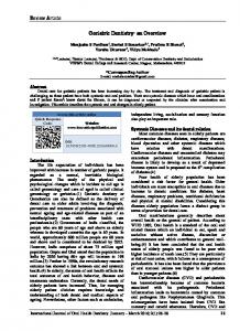
Vitrification may be applied either in situ or ex situ. For treatment of contaminated soils and groundwater, ex situ treatment is seldom economically viable or preferred over other ex situ options for organic contaminant treatment. For this reason, only in situ vitrification is discussed further in terms of WQARF site cleanup. ISV depends on melting the soil, which subsequently cools to form a glassy, impermeable monolith (Figure 6). The heating is done electrically by placing electrodes into the soil and using the soil's resistance to the passage of electricity to generate the heat necessary to create the melt. Soil temperatures reach 1600°C to 2000°C (Woodside, 1999). Placement of a horizontal graphite and glass fragment layer is often required between the electrodes to initiate the electrical passage. Once initiated, the melt continues outward from the initial path with melts extending up to about 20 feet depth depending on the electrode configuration (NRC, 1999). Organic contaminants are driven to the edge of the melt where they either volatilize or are incinerated. Trapping of the vapors at the surface is required to avoid exceeding air emission standards. Because the process is very energy intensive it is normally too expensive to be used, except where the contaminants are particularly difficult to treat (low volatility, mixed metal/organics, etc.) or where the soil is very heterogeneous with low permeability layers so that other less costly extraction or in situ techniques are not viable. Although not theoretically limited, this technique has not been used for to treat soil volumes deeper than about 20 feet.
25
Figure 6. Schematic of typical vitrification treatment process. (Adapted from www.geomelt.com, 03/15/01.)
4. ABIOTIC TRANSFORMATION METHODS Abiotic transformation methods may be applied either in the subsurface (in situ) or after removal of the contaminant to the surface (ex situ). Some methods may be applied in either location (i.e., Fenton's reagents), whereas other methods are only applicable either in the subsurface (i.e., reactive permeable barriers) or above ground after extraction (i.e., UV/peroxide). In-situ chemical transformation methods have the obvious potential advantage of destroying the contaminant in situ, obviating the need for aboveground treatment or disposal. On the other hand, ex situ treatment is not hindered by the same problems concerning delivery of the active reagents as in situ treatment and the use of photochemical reactions becomes viable for aboveground applications. The promotion of in-situ chemical transformations (e.g., oxidative/reductive reactions) has just started to receive significant attention. Technologies under current investigation include passive methods such as permeable reactive barriers employing zero-valent iron filings, and active methods based on injecting oxidative solutions (Fenton’s reagent, permanganate) into the target area. Despite a somewhat longer track record, ex situ methods are also under continued investigation, since progress in enhanced removal techniques has motivated new interest and innovation in aboveground transformation methods. The following discussion is organized by the general types of treatment methods regardless of the location of application and any location limitation is noted in the particular discussion.
26
Chemical Oxidation Physicochemical oxidation of organic compounds is based on the observation that nearly all organic compounds can be oxidized to carbon dioxide, water and other mineralized byproducts if a sufficiently strong oxidizer is present. A wide variety of potential techniques are available, although most depend on some variation of direct oxidation by either potassium permanganate or ozone, or on a process that generates hydroxyl radicals, which in turn are employed for destruction of the target compound(s). Therefore, the same basic process advantages and limitations tend to apply to ex situ oxidation technologies as in situ technologies. Oxidation treatments may be either in situ or ex situ and are typically distinguished by the identity of the oxidant used and whether or not a catalyst or energy source is incorporated to enhance the oxidation rate. Many of the oxidative techniques rely on generation of a hydroxyl radical (OH·), which is a highly reactive, nonspecific oxidant capable of degrading a wide variety of synthetic organic compounds. These techniques include treatment by ozone at high pH, ozone plus hydrogen peroxide, hydrogen peroxide plus UV light, and Fenton's reagents. For other techniques the chemical reagent added directly oxidizes the organic contaminant. Examples include direct ozonation, chlorination, and potassium permanganate. Nearly all of the oxidation techniques presently available treat the contaminant in the liquid phase, since the reagents are delivered in the liquid phase. Gas phase transformation of organics (with the exception of direct gas phase ozonation) is largely limited to reductive strategies such as catalytic dehalogenation using palladium and hydrogen gas (see discussion of reductive degradation). This limitation to liquid phase reactions restricts oxidative techniques to in situ application in either the saturated zone or an intentionally flooded portion of the vadose zone or to ex situ treatment of gas phase contaminants by transfer to a liquid phase. All of the oxidizing reagents used for treatment of organic, subsurface contamination are relatively non-selective and will react with most organics present in the subsurface. Therefore, soils and groundwaters containing high total organic carbon (TOC) concentrations can exhibit a high oxidant demand, despite the relatively low demand from the actual synthetic organic contaminant. The presence of significant soil heterogeneity and/or low permeability zones will also impact the effectiveness of any in situ oxidation strategy. Since treatment depends on the chemical oxidant being uniformly distributed to all zones of contamination, significant heterogeneity will cause preferential channeling of the oxidant containing fluid to the high conductivity zones with poor transport to the low conductivity zones, while low permeability layers will restrict access of the treatment fluid to areas of potential contamination. Three techniques, potassium permanganate, Fenton's reagents and ozone, have been applied both in situ (Brown et al., 1998b) and ex situ (Eckenfelder, 2000). Table 5 provides a comparative overview of application of these technologies in situ. This is followed by a discussion of hydroxyl radical oxidation techniques (other than Fenton's reagents) which are only presently considered to be applicable only ex situ. Potassium Permanganate Although only recently studied, the most promising oxidant for in situ treatment of organic contaminants is potassium permanganate (KMnO4). This oxidant has been shown to work well for chlorinated ethenes such as TCE and PCE, but has been less effective in treating organics without double bonds (Pankow and Cherry, 1996). Some laboratory work has indicated high concentrations of KMnO4 can oxidize chlorinated alkanes (i.e., trichloroethane), particularly
27
if catalysts are present (LaChance et al., 1998), but this work has been unverified in the field. In a laboratory study, the second-order rate constant for TCE oxidation by KMnO4 was observed to be 0.89 M-1 sec-1 at pH 7 and 20°C (Huang et al., 1999), which compares well with the kinetic rate for direct ozonation, but is much slower than the rate for hydroxyl radical oxidation. This relatively slow rate is often beneficial for in situ application as it allows the oxidant to be transported further into the porous media before it reacts with the natural organic matter and other reduced species in the subsurface. By-products from KMnO4 destruction of chlorinated ethenes are typically carbon dioxide, potassium and chloride ions, chlorine gas (which reacts with water to form hypochlorous acid), hydrochloric acid, dissolved manganese and precipitated manganese dioxide. Due to the by-product acidity, poorly buffered soils may experience a pH drop in the pore water. Thus, potential limitations specific to use of potassium permanganate for in situ oxidation are its selectivity for only chlorinated ethenes, the production of manganese oxides that may reduce permeability, and the release of protons, which in non-buffered soils may lead to the acid solubilization of some metal species.
Table 5. Comparison of oxidants used for in situ treatment. (Adapted from Basel and Nelson, 2000.) Fenton's Reagents Permanganate Ozone Physical state liquid liquid gas Hydroxyl radical yes only under very only under limited formation limited conditions conditions Oxidation 2.80 V 1.70V 2.07V potential (highest) Reaction times very fast slow fast Contaminant many organic primarily only some organic treatability contaminants chlorinated alkenes contaminants Direct by-products Fe(III), O2, H2O Mnaq, MnO2, & O2 potential metals unlikely yes, at low or Potential to enhance yes, if applied under bioremediation neutral conditions intermittent dosage Capital costs low low high Reagent/operation moderate moderate moderate costs Metal oxidation Notes May cause metals Can oxidize Cr(III) to Cr(VI). Increased potential. Potential mobilization if ionic strength of gas clogging of applied in acidic pore water. Potential pores conditions. Gas pore clogging. clogging of pores.
Schnarr et al. (1998) report a study in Canada where a contained area of soil that had been intentionally contaminated with pure phase PCE and TCE was largely remediated after flushing with approximately six pore volumes of KMnO4 amended water. In a larger field test at a DOE site in Ohio, about 0.77 pore volumes of KMnO4 was injected into a DNAPL contaminated zone (primarily TCE) and concentrations were immediately lowered to below
28
detection limit from concentration originally in hundreds of thousands of micrograms per liter. After several weeks the concentrations rebounded somewhat to hundreds of micrograms per liter indicating much, but not all, of the DNAPLs had been destroyed (NRC, 1998). Pilot-scale tests of potassium permanganate injection have recently been conducted at the AFP 44 Superfund site in Tucson. Preliminary results indicate that the permanganate was effective in reducing TCE concentrations, without promoting significant chromium mobilization or changes in permeability or pH (Brusseau, unpublished data). Potassium permanganate is more appealing for subsurface application than the other oxidants, because it has a much higher water solubility than hydrogen peroxide and has neither the very limited subsurface lifespan or the strong pH dependence of both hydrogen peroxide and ozone (see subsequent discussions). However, because KMnO4 has only recently been studied as a potential subsurface oxidant (Huang et al., 1999), additional testing is needed. A large-scale test of KMnO4 is underway in New Hampshire and it is expected the results from this study greatly aid in evaluating the practical aspects of this oxidative strategy (McKay et al., 1998). Both ozone and potassium permanganate have been used for decades as oxidants for disinfection and purification of drinking water (Singer and Reckhow, 1999). However, since disinfection of the fluids extracted from contaminated sites is seldom an issue (and, in fact, microbial processes are often beneficial), these direct oxidation methods are typically not chosen over the kinetically faster hydroxyl radical pathway. The primary exceptions are for groundwater that exhibits either high total organic carbon (TOC) or high carbonate or chloride concentrations. NOM, carbonate species and chloride are all effective scavengers of hydroxyl radicals and their concentration may be several orders of magnitude higher than that of the target compound. Thus, waters containing high concentrations of these species will not be effectively treated by hydroxyl radical generating processes and may be more practically treated by a direct oxidation process. Fenton's Reagents Fenton's reaction is the pseudo-catalytic decomposition of hydrogen peroxide (H2O2) by oxidized iron. In the reaction Fe(II) reacts with H2O2 to yield Fe(III), a hydroxyl radical (OH·), and a hydroxyl ion (OH-). The Fe(III), in turn, reacts with H2O2 to return to Fe(II) plus a proton (H+) and a superoxide radical (HO2·). The hydroxyl radical produced in the iron oxidation step can be used to degrade organic contaminants such as PCE and TCE (Aieta et al., 1988). Due to the ubiquitous presence of iron in minerals, Fenton's reaction will proceed spontaneously in nearly all cases where H2O2 is introduced into the subsurface (Brown and Norris, 1994). However, to force the reaction to proceed at an efficient rate for organic contaminant remediation, typically high concentrations of H2O2 are added along with chelated iron, near saturation Fe(III) solutions or heterogeneous colloidal iron catalysts (Watts et al., 1997). The use of Fenton's reaction in situ is appealing because it avoids the need for liquid extraction to the surface, its reagents react to nontoxic compounds such as water and oxygen, it potentially completely mineralizes toxic organics to water, carbon dioxide, and salts, and it utilizes relatively cheap, non-hazardous reagents of hydrogen peroxide and iron. However, several aspects of subsurface treatment make this process only moderately practical at most synthetic organic contaminated sites. The rate of Fenton's reaction is greatly enhanced in acidic conditions, which may be difficult to achieve in the subsurface mineralogical environment due to the common occurrence of acid-soluble solids such as calcium carbonate (limestone) which buffer the solution to a near neutral pH (Miller et al., 1996). Recent work indicates that addition of chelated metal catalysts may allow a "Fenton-like" reaction to proceed at a useful rate at
29
neutral pH (Basel and Nelson, 2000), which would greatly increase the feasibility of widespread use of this technology. Hydrogen peroxide is also difficult to deliver to the contaminant zone if it is any distance from the reagent injection point. H2O2 has a limited lifespan of a few hours in a normal subsurface environment, so transport away from the well is limited to less than ten meters and often only a few meters before the H2O2 decomposes (Pardieck et al., 1992). Finally, as hydrogen peroxide decomposes it releases oxygen which may create trapped gas bubbles in the porous media and further retard liquid mobility and delivery of liquid-phase reagents (NRC, 1999). Ozone Ozone (O3) is a strong oxidant and has been suggested as a possible in situ oxidant. Ozone has the advantage over potassium permanganate and Fenton's reagents in that it can be produced on site using oxygen from ambient air after dehumidification. Ozone degrades organic compounds by two pathways, direct ozonation and decomposition to hydroxyl radicals. The latter pathway yields organic reaction kinetics that a many orders of magnitude faster than direct ozonation. For instance the second-order rate constant for PCE oxidation by direct ozonation is