Parallel Pattern Recognition Computations within a Wireless Sensor Network A. I. Khan Monash University, Australia
[email protected] Abstract The computational properties of a wireless sensor network (WSN) have been investigated by implementing a fully distributed pattern recognition algorithm within the network. It is shown that the set up allows a physical object to develop a capability, which to some extent may be considered similar to our sense of touch, with the WSN acting as an artificial nervous system in this regard. The effectiveness of the algorithm is inspected by comparing the outputs from the sensors with the stress patterns generated through a simple finite element model and then stored within the network. It is shown that the test object could successfully differentiate between its internal stress states resulting from the changes to its external loading conditions. Suitability of the algorithm is discussed with respect to the data storage requirement per node of the WSN.
1. Introduction With the advent of wireless enabled MEM devices, such as the Berkeley’s motes, there is an increasing awareness of the potential of these systems. The impact of MEM based WSN is briefly outlined by Rabaey [4]. The design and operation of such devices is beyond the scope of this paper, however information on the design issues and their communication networks may be found in [2]. The very limited architecture of MEM devices requires a minimalist approach to be adopted in the software design [1]. The physical size of the wireless sensor devices now ranges within a few cubic millimeters in volume and it’s possible to produce these devices very economically. It is envisaged the sizes would continue to reduce, and the power supply may come from sources such as the sunlight or the radio frequency electromagnetic energy. A coarse grained network, comprising wireless MEM devices such as Berkeley motes, may conduct most of the sensor data processing in-situ and communicate only the final results to the observer. In such a model it is possible to monitor a very large number of dedicated wireless sensor
P. Mihailescu Intelligent Research Lab, BT Exact, UK
[email protected] networks (each monitoring a specific environment or a component) without requiring a massive computational resource at the observer’s end. Alternatively, a very fine grained network, comprising RFID like chips, would have to convey most of the sensor information to a remote application monitoring such a system.
2. Pattern Recognition within a WSN We could derive meaningful information by correlating the input patterns, gathered in-situ, with the patterns calculated by a numerical modeling technique such as the finite element analysis and stored within the associative memory of a WSN. Considering the associative memory must be implemented within a network with a very limited computational resource, the governing algorithm must be modified to suit the limitations of the operating environment. This would generally entail in complex sequential algorithms being replaced with parallel/decentralised ones. Also some drop in the level of the effectiveness may occur, which could be offset by the post processing at the remote system’s end. In this paper a very simple graph-based pattern recognition algorithm, hence forth referred to as the Graph Neuron (GN), is presented for use within the WSN. The proposed algorithm is not intended as an improvement to the highly sophisticated pattern recognition methods already available in the literature; focus instead is on reducing the computational requirements for use within resource-restricted networks and providing responses in real-time. The material stresses, computed using finite element analysis [7], were employed as the patterns for testing the proposed algorithm. The algorithm may however be used for any other system capable of being modeled using a numerical technique or an empirical approach.
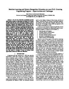
3. Graph Neuron Overview A pattern is denoted as a set of value and position pairs p(val, pos). Each node within the network is preprogrammed to respond to a specific signal i.e. a p(val, pos) pair. The entire pattern is presented to the network as shown
0-7695-2128-2/04 $20.00 (C) 2004 IEEE
store
An input pattern
recall
p(val, pos) pairs X
A GN Array
X
1
O
2
O N1000 X
X,1
X
An adjacent GN information exchange
Pre-programmed values
Figure 1. Pattern input and recall within a typical Graph Neuron Array
N1003 O,2
in Figure 1 and the response of the network/array is noted by the observer. Each node works independently to determine whether any of the pairs within the pattern is matched with its pre-programmed value. In the case of a match the node consults its adjacent nodes and then either stores the subpattern or registers a recall. The mapping of the pairs to the appropriate nodes within the network is shown in Figure 2. The Graph Neuron algorithm allows the use of a very large number of parallel processors within recursively connected domains [3] of Peer-to-Peer networks [5] [6] [8]. The algorithm is thus capable of providing a near instantaneous response time to the inputs using relatively low-performance processors. A detailed description of the algorithm may be seen in [3].
4. Identification of Stress States by a Simple GN Array A relatively simple finite element discretisation was used to program a GN based network in order to demonstrate that the stress distributions, within a structural element, may be successfully identified. In this regard the three main stress distributions i.e. σx , σy , and σxy were induced by a single in-plane load acting in the horizontal direction on a thin L-shaped plate. The process was repeated with the same load but this time acting in the vertical direction. The stress distributions computed using this finite element model are shown in Figures 3 and 4 respectively. The stress patterns σx , the longitudinal stress pattern for the load acting in the horizontal direction, and σxy, the shear stress pattern for the load acting in the vertical direction, were selected at random to test the pattern recognition algorithm. It should be pointed out that the stress states, shown in the Figures, were produced entirely by the finite element analysis and hence the GN had no influence over the quality or the make-up of the input patterns. In order to test the algorithm, the array was exposed to the σx stress state pattern from the horizontal load case and the σxy stress state
3
N1002 X,3
Figure 2. A text string comprising characters ‘X’ and ‘O’ being mapped to the appropriate nodes within the array using the input pairs p1 (X, 1), p2 (O, 2), p3 (X, 3).
pattern from the vertical load case; the patterns were memorised by array. Upon all the stress states being presented to the array, the array was expected to respond unequivocally to the patterns it had been exposed to previously. Other patterns were expected to invoke only partial recall responses. It was assumed that a finite element would either be in a state of positive stress state (tension) or it would be in a negative stress state (compression). Hence a binary set of characters, X and O, was sufficient to define the stress values within the patterns in this case. The position for each stress value was denoted by the corresponding mesh element in the discretisation. Since the mesh comprised six elements; a network of 2 ∗ 6 = 12 GNs was set up to cater for each element in the finite element mesh. By setting the number of GNs as a integer multiple of the number of elements in the finite element mesh, it was possible to define an unequivocal response from the array - exactly six GNs had to agree before a response could be accepted in this case. By maintaining this relationship it was also possible to differentiate between the six stress states. The network input patterns corresponding to these stress states, are shown in Table 1. Stress patterns P1 and P6 were first introduced to the array, which led to the storage of these patterns. Later all six patterns were sequentially presented to the array. The array storage and recall responses are shown in Figure 5. It may be seen from the Figure that P1 and P6 , marked with the asterisk, set six of the GNs within the array to the recall status. It may also be noted that no memorisation activity occurs within the array when these patterns are presented
0-7695-2128-2/04 $20.00 (C) 2004 IEEE
Sy-100H
Sx-100H 0.22E+01 0.17E+01 0.13E+01 0.87E+00 0.44E+00 0.00E+00 -.44E+00 -.87E+00 -.13E+01 -.17E+01 -.22E+01
5 6
1
5 6
3
1
2
Sxy-100H 0.31E+01 0.24E+01 0.18E+01 0.12E+01 0.61E+00 0.00E+00 -.61E+00 -.12E+01 -.18E+01 -.24E+01 -.31E+01
4
5 6
3 2
0.24E+01 0.19E+01 0.14E+01 0.94E+00 0.47E+00 0.00E+00 -.47E+00 -.94E+00 -.14E+01 -.19E+01 -.24E+01
1
3
4
2
4
Figure 3. σx , σy , and σxy for the horizontal load condition
Sx-100V
5 6
1
Sxy-100V
Sy-100V 0.90E+00 0.72E+00 0.54E+00 0.36E+00 0.18E+00 0.00E+00 -.18E+00 -.36E+00 -.54E+00 -.72E+00 -.90E+00
5 6
3
1
2
0.36E+01 0.29E+01 0.22E+01 0.14E+01 0.72E+00 0.00E+00 -.72E+00 -.14E+01 -.22E+01 -.29E+01 -.36E+01
4
5 6
1
3 2
0.11E+01 0.88E+00 0.66E+00 0.44E+00 0.22E+00 0.00E+00 -.22E+00 -.44E+00 -.66E+00 -.88E+00 -.11E+01
3 2
4
4
Figure 4. σx , σy , and σxy for the vertical load condition
Stress Pattern (P)
1
2
3
4
5
6
P1 = σx 100H
X
X
X
O
O
X
P2 = σy 100H
X
X
X
O
X
O
P3 = σxy 100H
X
X
O
X
X
X
P4 = σx 100V
X
X
X
X
O
X
P5 = σy 100V
X
X
X
X
X
X
P6 = σxy 100V
X
X
O
O
O
X
Pattern Stored
P1
Patterns Detected
P6
Table 1. The stress state patterns corresponding to the horizontal and the vertical load conditions
again. Other patterns evoke mixed responses from the network. Figure 5 shows that stress states may be detected by employing a fully distributed pattern recognition algorithm within a sensors based network. It may however be noted that the responses from the network are limited to detecting regions of positive and negative stress only at this stage.
5. Storage requirements within the GN nodes Each node within the GN array stores a subpattern (of the input pattern) within a vector termed as the bias ar-
P1*
P2
P3
P4
GN Memorisation
P5
P6*
GN Recall
Figure 5. The pattern storage and the pattern recall outputs relating to the six stress states.
ray [3]. This array primarily determines the storage capacity required on each node of the network. The update of the bias array may be done in two different ways. We may either allocate a new row in the array for each input pattern or we may re-use an existing row if it matches with a previously stored subpattern. The former scheme would lead to a greater pattern matching accuracy but it would also require
0-7695-2128-2/04 $20.00 (C) 2004 IEEE
A
1
2
b(2)
b(2)
b(0)
3
4
Bias entry for GN(A,1) does not increment for P4
6. Concluding Remarks B b(1)
b(3)
b(2)
b(1) b(0)
Max bias entry b(3) occurs for GN(B,2)
C
D
b(0)
b(0)
b(1)
b(0)
b(0) b(2)
b(0)
b(1)
Figure 6. Arbitrary Strings P1: ABBD, P2: ACCB, P3: BACA, P4: ABCD mapped on to the array.
some what more storage per node. The second bias update scheme is of more interest to us from the WSN perspective where a minimalistic approach is favoured in the software design [1]. The scheme may be demonstrated with a simple example using a pattern space of a four lettered word comprising a set of four alphabets, A, B, C, and D. The total number of possible combinations in this case would be 44 = 256 and the GN array of size 4 x 4 would be required for this pattern space. The process of re-using the bias entry for a matching subpattern previously stored within the node is shown using an arbitrary set of subpatterns in Figure 6. The Figure also shows that the maximum entries within the bias array remains less than the total number of input patterns in comparison to the first scheme, where the maximum row size of bias must match the total number of the input patterns. In this regard, it may be seen from Figure 5 that patterns P2 , . . . P5 show partial recalls. These partial recalls occur due to the storage conservation scheme outlined above. Assuming R1 is a set of n patterns stored out of a total pattern space, R, comprising N patterns. The accuracy of recalls for the storage scheme, as shown in Figure 6, would depend upon the uniqueness of R1 versus the remaining patterns R2 ∈ R where, R2 ≡ R − R1
The paper demonstrates the potential of carrying out pattern recognition computations within the WSN itself. The problem size for the tests was purposefully limited in order to observe a stepwise progression of the algorithm. The proposed scheme however has the potential to be scaledup to large-scale networks. The pattern recognition ability demonstrated at this stage is limited to a binary type of pattern variation - an mesh element could be either in a positive or a negative stress state. The next stage of development would be to extend the algorithm in a manner where a range of values per mesh element may be used for the pattern storage and the pattern recall operations.
References [1] D. E. Culler, J. Hill, P. Buonadonna, and R. Szewczyk. A network-centric approach to embedded software for tiny devices. In Proceedings of the EMSOFT 2001, 2001. [2] J. M. Kahn, R. H. Katz, and K. S. J. Pister. Mobile networking for smart dust. In Proceedings of the ACM/IEEE Intl. Conf. on Mobile Computing and Networking (MobiCom 99), Seattle, WA, August 17-19, 1999. [3] A. I. Khan. A peer-to-peer associative memory network for intelligent information systems. In Proceedings of the Thirteenth Australasian Conference on Information Systems, volume 1, 2002. [4] J. Rabaey. Ultra low-power computation and communication enables ambient intelligence. In Proceedings of the Smart Objects Conference, Grenoble, 2003. [5] A. Rowstron and P. Druschel. Pastry: Scalable, distributed object location and routing for large-scale peer-to-peer systems. In Proceedings of the IFIP/ACM Middleware 2001, Heidelberg, Germany, Nov. 2001, 2001. [6] S. Senaratna and A. I. Khan. Autonomous clustering algorithms for serverless peer-to-peer (p2p) systems. In Proceedings of the 6th International Conference on High Performance Computing in Asia-Pacific Region, Bangalore, India, volume 2, 2002. [7] B. H. V. Topping and A. I. Khan. Parallel Finite Element Computations. Sax-Coburg Publications, 10 Saxe-Coburg Place, Edinburgh, EH3 5BR, UK, 1996. [8] W. Ye, A. I. Khan, and E. A. Kendall. Distributed network file storage for a serverless (p2p) network. In Proceedings of the 11th IEEE International Conference on Networks (ICON2003), Sydney, Australia, 2003.
In other words a partial recall is caused by some parts of the input (pattern) being matched with a previously stored subpattern since we have opted to re-use the bias rows entries of these subpatterns. The partial recalls do not constitute a problem when dealing with situations where complete patterns are specified. The partial recalls may however lead to problems when noisy/incomplete patterns are presented for processing.
0-7695-2128-2/04 $20.00 (C) 2004 IEEE