ow and an algorithm to rst allocate software and hardware components, and then partition ..... After each producer FSMD has produced the required number of.
Partitioning and Pipelining for Performance-Constrained Hardware/Software Systems Smita Bakshi Dept. of Electrical and Computer Engineering University of California, Davis Davis, CA 95616 Daniel D. Gajski Dept. of Information and Computer Science University of California, Irvine Irvine, CA 92629-3425 y
Category: System-Level Synthesis (Hardware/Software Co-design) Keywords: digital design, high-performance, image-processing partitioning, performance-tradeo�s, pipelining, system-level
Abstract
In order to satisfy cost and performance requirements, digital signal processing and telecommunication systems, are generally implemented with a combination of di�erent components, from custom-designed chips to o�-the-shelf processors. These components vary in their area, performance, programmability and so on, and the system functionality is partitioned amongst the components to best utilize this tradeo�. However, for performance critical designs, it is not su�cient to only implement the critical sections as custom-designed high-performance hardware, but it is also necessary to pipeline the system at several levels of granularity. We present a design
ow and an algorithm to rst allocate software and hardware components, and then partition and pipeline a throughput-constrained speci cation amongst the selected components. This is performed to best satisfy the throughput constraint at minimal hardware cost. Our ability to incorporate partitioning with pipelining at several levels of granularity, enables us to attain high throughput designs, and also distinguishes our work from previously proposed hardware/software partitioning algorithms. yThis work was performed while the author was at UC Irvine. It has been supported by SRC grant #93-DJ-146. The authors gratefully acknowledge their support.
1 Introduction Digital systems, especially in the domain of digital processing and telecommunications, are immensely complex. In order to deal with the high complexity, increased time-to-market pressures, and a set of possibly con icting constraints, it is now imperative to involve design automation at the highest possible level. This \highest possible level" may vary on the design, but given the fact that an increasing number of designs now contain a combination of di�erent component types, such as general-purpose processors, DSP (digital signal processing) cores, and custom designed ASICs (application speci c integrated circuits), we consider the highest level of design to be the one involving the selection and interconnection of such components. We refer to this as system-level design. The reason why a system is best composed of di�erent component types is due to the di�erent characteristics of the components, which may be targeted at satisfying di�erent constraints. O�-theshelf processors o�er high-programmability, lower design time, and a comparatively lower cost and lower performance than an equivalent ASIC implementation. On the other hand, ASICs are more expensive to design and fabricate, but o�er comparatively higher performance. Thus, for a given system, these components are selected such that the performance critical sections are performed rapidly on ASICs, and the less critical sections, or the sections that require higher programmability, are performed on the processors. Our work addresses the synthesis of throughput constrained systems. In order to meet the throughput constraints of these systems, it is not su�cient to only perform the critical sections in hardware, but it is also necessary to pipeline the design. Pipelining divides the design into concurrently executing stages, thus increasing its e�ective data rate. However, the increased concurrency can only be handled with an increased number of resources (or with faster resources). Hence, in designing a \cost-optimal" pipeline using hardware and software components, it is necessary to integrate the selection of the components, the functional partitioning of the system amongst the components, and lastly, the division of the system into pipe stages. Given a speci cation of such a throughput-constrained system, we present a design ow and a set of algorithms to determine (1) an allocation of system-level components, (2) a functional partition, and (3) a pipeline to implement the system at minimal hardware cost. Our work supports pipelining at four di�erent levels of the design, namely the system, behavior, loop and operation level. The integrated component selection, partitioning, and multi-level pipelining enables us to design highthroughput hardware/software systems. The rest of the paper is organized as follows. In the next section, we describe previous work in the area of hardware/software codesign and position it with respect to our work in hardware/software pipelining. In Section 3, we de ne the problem of hardware/software partitioning and pipelining, and in Sections 4 and 5 we describe our model and algorithm, respectively. We provide experimental results in Section 7 and end with our conclusions in Section 8.
1
2 Previous work Over the past ve years, several hardware/software codesign systems have been developed, some in industry but mainly in academia. These systems are based on di�erent design methodologies and hence concentrate on di�erent aspects of the hardware/software codesign problem. For instance, SpecSyn [6], Cosyma [5], and Vulcan II [9] are codesign tools that focus on hardware and software estimation and on the functional partitioning of a given speci cation amongst hardware and software components, such as ASICs and processors. They di�er in the level of granularity of partitioning (process vs. statement blocks) and in their partitioning approach (starting with all software vs. all hardware). Other synthesis systems such as Ptolemy [14] [13] and Chinook [4] focus on di�erent aspects of the hardware/software codesign problem. Ptolemy provides an environment for specifying, simulating and prototyping DSP applications. It concentrates on hardware/software co-simulation and on code generation, rather than on hardware/software partitioning and estimation. Chinook concentrates on the synthesis of hardware and software interfaces, and like Ptolemy, it requires the user to manually specify the hardware and software partition. Our work in hardware/software codesign focuses on performance-constrained functional partitioning for data ow dominated systems. However, in addition to performing spatial partitioning, that is, dividing the speci cation into a hardware and software space, we also perform temporal partitioning in which we divide the speci cation into pipe stages that execute concurrently, so as to achieve high data rates. Spatial and temporal partitioning are interdependent problems, since the division of tasks into pipe stages depends on their execution delay, which in turn, depends on the resources (hardware and/or software) used to implement the tasks. Hence, our algorithms consider both problems together, and determine a hardware/software partition as well as the number of pipe stages and an implementation for each pipe stage. In comparing our work with the systems mentioned above, we have, in general, extended the design space explored by these systems by allowing designs to be pipelined at the system and the task level. Systems such as SpecSyn, Cosyma, and Vulcan II assume that the tasks in the system execute sequentially, in a non-pipelined fashion. Furthermore, they also assume that the operations within each task execute sequentially. In our designs, not only can the system be pipelined, but the operations within each task may also be pipelined. Hence, our work extends current algorithms by performing hierarchical pipelining and by so doing, it achieves partitions with high
throughput values that are unattainable by other existing partitioning and estimation algorithms.
After a speci cation has been pipelined and partitioned amongst hardware and software components, we still require to perform the tasks of interface re nement, code generation and co-simulation. Thus, while our work is directly related to codesign systems performing partitioning, it is orthogonal to systems such as Ptolemy and Chinook that concentrate on the tasks carried out after partitioning and estimation.
2
3 Problem de nition Our problem of hardware/software partitioning and pipelining may be de ned as follows:
Given:
1. A speci cation of the system as a control ow graph (CFG) of behaviors or tasks. 2. A hardware library containing functional units characterized by a three-tuple . 3. A software/processor library containing a list of processors characterized by a four-tuple . 4. A clock constraint and a throughput constraint for the complete speci cation.
Determine: 1. An implementation type (either software or hardware) for every behavior. 2. The estimated area for each hardware behavior, as well as the total hardware area for the complete speci cation. 3. The processor to be used for each software behavior, as well as the total number of processors for the complete speci cation 4. A division of the control ow graph into pipe stages of delay no more than the given throughput constraint.
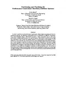
Such that: 1. Constraints on throughput are satis ed, and 2. Total hardware area (for the given clock) is minimized. The throughput constraint speci es the di�erence in the arrival time (in nanoseconds) of two consecutive input samples. We also refer to this time as the PS (pipe stage) delay, since this would be the required delay of a pipe stage in the design, if it were to be pipelined. Note, that the number of stages in the design is determined by our algorithm, and it depends on the critical path of the CFG and on the PS delay constraint. The example in Figure 1 illustrates the problem de ned above. As input we have a control ow graph of behaviors, a hardware and a software library, and a PS delay (throughput) and clock constraint. The control ow graph is derived from a SpecChart speci cation, details of which are provided in Section 5.1. The nodes in the control ow graph represent behaviors and the arcs represent control dependencies. Thus behaviors B and C can begin only when behavior A has completed, and similarly behavior D can begin only when both behaviors B and C have completed. Each behavior contains a sequence of VHDL statements that represents computation done on variables. Data dependencies are not explicitly depicted in the control ow graph. 3
Input Control Flow Graph Type
Name
A B
C D
Node: behavior Arc: control flow
Software Library
Hardware Library Delay
Area
(ns)
(gates)
* * *
Mpy1 Mpy2 Mpy3
30 50 70
100 70 60
+ +
Add1 Add2
30 42
45 30
> =
Cmp1 Cmp2
18 14
12 8
Type
Clock $ Cost Metrics File (ns) Pentium 90 10 pentium.metrics PowerPC 10 75 powerpc.metrics 68000 50 60 mot68000.metrics
Constraints: Clock = 10 ns PS delay = 4000 ns
E
Output Pipelined & Partitioned Control Flow Graph
System Pipeline time
pentium 0
stage 1
68000
A
A
C
B
1 Mpy1, 2 Add2 8x16 mem
stage 1
3100 4000
A C
A C
B stage 2
stage 2
pentium C
D
D E
E
3 Mpy1, 1 Mpy2 2 Add2
4000
4000
68000 D
stage 3
stage 3
HW
B
pentium
Aim: Satisfy PS delay constraint Minimize hardware area
HW
4000
ASIC
Figure 1: Illustrating the inputs and outputs of the combined hardware/software partitioning and pipelining algorithm.
4
The hardware library consists of a set of functional units with their corresponding delay (in ns) and area (in gates). Note that there may be multiple implementations with di�erent area and delay values of the same operator type, such as Mpy1, Mpy2 and Mpy3. The software library contains a list of processors with their corresponding clock speeds, dollar cost and metrics le. The metrics le gives the number of instruction cycles and the number of bytes required to execute each of a list of 3-address generic instructions on that processor. This information characterizes a processor and is required to estimate the execution time of a behavior on a speci c processor [7]. The clock constraint of 10 ns indicates that each of the hardware behaviors will operate at a clock frequency of 100 MHz and this clock value is used while estimating the area and delay of the hardware behaviors. Finally, the PS delay constraint indicates that a new sample of input data will be introduced every 4000 ns and thus, if the design is pipelined, each pipe stage should have a delay no more than 4000 ns. The output consists of a pipelined and partitioned CFG where every behavior has been mapped to either hardware or software and the graph has been divided into pipe stages of delay no more than 4000 ns. Every hardware behavior is associated with an estimate of its execution time and the number and type of components (selected from the hardware library) needed to obtain that execution time. For instance, behavior E has a throughput of 4000 ns and requires 3 instances of Mpy1, 1 instance of Mpy2 and 2 instances of Add2, bringing the total area to 430 gates. Similarly, every software behavior is associated with a processor from the software library, and its execution time on that processor. For instance, behavior A implemented on the Pentium processor, has an execution time of 3100 ns. Finally, the CFG has also been partitioned into three pipe stages such that the throughput of the system is 4000 ns, that is each pipe stage has a delay of no more than 4000 ns. The hardware and software partitioning and pipelining has been done with the aim of satisfying the throughput constraint at minimal hardware cost. This scheduling and pipelining information is represented in the System Pipeline diagram, which depicts all the pipe stages and the execution schedule of behaviors within each pipe stage. Before we describe our algorithm to solve this problem, note our assumptions on how resources are shared amongst behaviors:
� Two software behaviors may share the same processor, irrespective of the pipe stages they execute in. For instance, in Figure 1, behaviors A and D are mapped to the same Pentium processor, even though they execute in di�erent pipe stages. Behavior A executes in stage 1 from time 0 ns till time 3100 ns and behavior D executes in stage 2 from time 3100 till time 4000 ns. Since all pipe stages execute concurrently, the only criteria that needs to be satis ed is that the behaviors should execute at non-overlapping times.
� Two hardware behaviors may not share resources. Thus, even though both behaviors C and E use Mpy1 they may not share the same multiplier. Note that this assumption is not a limitation of our model, but of our algorithm at this point. 5
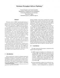
4 Pipelined Architecture Memory
Processor
Bus 2 Bus 1
Application Specific Integrated Circuit (ASIC)
ASIC
Processor
Figure 2: System Architecture. Having de ned our problem, we now introduce our system architecture. The system consists of one or more processors, one or more ASICs (application speci c integrated circuits), and one or more memory chips that all communicate over one or more buses (Figure 2). The memory stores data that needs to be transferred between pipe stages as well as any globally de ned data that may be accessed by multiple processors and/or ASICs. In this paper, we assume that all hardware behaviors are mapped onto 1 ASIC. After the pipelining and the partitioning, this ASIC may be further partitioned into smaller ASICs [8] [17]. 1 Decoder
2
1
Dequantizer
1
2 IDCT
2
3
4 5
3 Sum
Display
6 7
Predictor
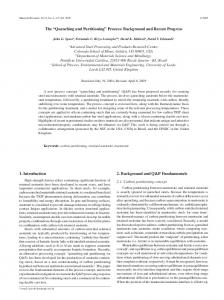
Figure 3: The MPEG1 decoder: an example of a pipelined system. The entire system can be viewed as a sequence of communicating pipelined FSMDs (Finite State Machine with Datapath). As an example, consider the MPEG1 (Motion Pictures Expert Group) decoder system shown in Figure 3. It consists of six pipelined FSMDs namely the Decoder, Dequantizer, IDCT (Inverse Discrete Cosine Transform), Sum, Predictor and Display. The system is pipelined, both at the behavior or block level (that is within an FSMD) and at the system level (that is between consecutive FSMDs). Figure 4 zooms into the Dequantizer, IDCT, and Sum blocks and it is used to illustrate the interface between two pipelined FSMDs. The Dequantizer consists of a controller and a 2-stage 6
pipelined datapath. Its output, Array A, a 64-element array, is consumed by the IDCT which consists of a controller and a 3-stage pipelined datapath with two memories. The output of the IDCT, in turn, is consumed by the Sum block. From Decoder
Dequantizer
ADD_GEN_B
MEM_A MEM_B
stage 2
*
CONTROL_DEQUANT
stage 1
ADD_GEN_A
stage 1
START
* +
IDCT
START
Array_A(0 to 63)
ADD_GEN_D
ADD_GEN_C
128
MEM_C
MEM_D
CONTROL_IDCT
0
stage 2
stage 2
*
*
* +
+ +
stage 3 Sum
*
From Predictor
Array_C(0 to 63)
START CONTROL_SUM
stage 1
MEM_E
stage 3
+ START
Figure 4: The interface between pipelined FSMDs. In order to maintain the ow of data in the pipeline it is assumed that the consumption and production rate of a data stream is the same. Thus, in Figure 4, the Dequantizer block produces a sample of the 64-element Array A, say, every 4000 ns and the IDCT consumes it at the same rate. We also assume that all pipelined FSMDs require a xed number of samples per input before they can begin processing data. After each producer FSMD has produced the required number of samples, it sends a START signal to its consumer FSMD indicating that the consumer may now begin execution. An FSMD can start after all its producers have sent START signals. Finally, we assume that each pipelined FSMD has su�cient memory to store two sets of samples per input, one the sample being currently used and the other, the sample being currently produced by the preceding FSMD. This approach of storing two samples per input, also known as doublebu�ering, represents the maximum amount of memory required for communication; hence, it is an expensive solution. The size of this memory may be reduced by determining the sequence in which data is produced and consumed and hence determining the number of variables that are alive at any given time. The size may be further reduced by transforming the data ow so that the read and write sequences match as closely as possible. 7
5 Algorithm Having de ned the problem and model, we now present the algorithm for the combined problem of hardware software partitioning and pipelining, an overview of which is presented in Figure 5.
Step 4
Step 1
Build control flow graph from SpecChart specification
Step2
Determine hardware/software partition
Determine area of resources for all hardware behaviors
No
Determine initial cheapest processor allocation
Step 3
Throughput satisfied?
Yes Resources not fast enough. Stop.
Pipeline and schedule control flow graph
Step 5
Yes Minimal hw area pipeline & schedule achieved. Stop.
Throughput satisfied?
No Modify processor allocation
Step 6
Figure 5: Overview of the algorithm for hardware software partitioning and pipelining. Given a SpecChart [15] speci cation, hardware and software libraries, a throughput constraint, and a clock constraint, the rst step consists of deriving the control ow graph from the given speci cation. A type (hardware or software) is then determined for every behavior in the CFG. This determination is based on the assumption that a software implementation is always less costly than an equivalent hardware implementation for a given behavior; hence, our algorithm attempts to execute as many as possible behaviors in software, using as many processors as needed. A behavior will be executed in hardware only if a processor is unable to satisfy the constraint. In the next step, we determine the number and type of hardware resources to be used for each of the hardware behaviors, and similarly we determine the total number and type of processors to be used by all the software behaviors. We then schedule and pipeline the control ow graph, that is, we determine a pipe stage and a time slot within the pipe stage for each behavior to execute in. If we can not determine a valid schedule and pipeline, we increase the speed and/or the number of processors and repeat the scheduling and pipelining step. This is repeated till constraints are satis ed, and in the worst case, this may be repeated till there are as many processors as software behaviors in the CFG. In the next few sections we describe each of the six steps of our algorithm. 8
5.1 Step 1: Building the CFG Behavior TOP type sequential is begin A: (TOC, true, BCDE); BCDE: (TOC, true,F); F: (TOC, true,STOP); Behavior A type leaf is begin −− contains VHDL code end A; Behavior BCDE type concurrent is begin BDE: ; C: ;
Control Flow Graph
Behavior BDE type sequential is begin
A
B: (TOC, value > 0, D) (TOC, value 0, D) (TOC, value 0 then behavior D will be executed else if value