position, and pressure regulator per inner tube. These all work to regulate the air flow into the inner tubes and ultimately the pressure in each tube. Finally, the ...
Pneumatically Controlled Angular Arm Joshua Sapers April 2015
1
Abstract
There has been little work on using pneumatics for practical arm control, and that work is focused on tension using McKibben Actuators or artificial muscles[3]. These methods are bulky and made to simulate muscles for medical or research purposes. A new method of using pneumatics and a actuator is needed in order to make a usable pneumatic arm a reality. The purpose of this paper is to explore the reasonableness of using pneumatics as an arm control mechanism. A novel method of pneumatic actuation for multi-degree-of-freedom controllers is proposed. The arm consists of three separate systems: mechanical, pneumatic, and control. The mechanical design consists of a spherical bearing to provide the degrees-of-freedom, and two plates, connected by the bearing to act as lever arms against each other. Two bicycle inner tubes were inflated in order to change the angle between the two plates. The pneumatics system comprises of one three way two position valve, two way two position, and pressure regulator per inner tube. These all work to regulate the air flow into the inner tubes and ultimately the pressure in each tube. Finally, the control code uses information from an accelerometer gyroscope and a PID to control the amount of time the valves are open. After the arm was prototyped, it was tested for accuracy. The arm was able to move to a specified position accurate to less than half a degree. By tuning the parameters, the accuracy could be raised, but it put too much strain on the system. Overall, The prototype proved that it can be controlled to a desired position. Further refinement will improve accuracy and consistency.
1
2
Introduction
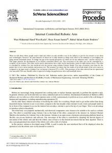
The object of this study is to characterize and investigate the feasibility of a compact compression based pneumatically driven arm. The arm used in the study operates in 2-dimensional polar space. The system was split in to three subsystems: The mechanical system, the feedback control, and the pneumatic control. The control process operates in a cycle with the feedback loop controlling the pneumatics, the pneumatics driving the mechanical system, and the mechanical system providing information to the arm. Feedback Control Loop
MPU-6050 Accelerometer Gyroscope
Pneumatic Control Mechanical System
Steel Rod
Aduino Uno Top Plate
Bottom Plate
Inner Tube 3 Way 2 Position Valve (Normally Closed)
2 Way 2 Position Valve (Normally Closed) Air Source
Figure 1: The three subsystems and their components. Orange represents the mechanical system, blue represents the feedback control loop, and green is the pneumatic system. The blue arrows and green arrows represent digital signals and air flow respectively
3
Mechanical Design
For the design of the system, two steel circular plates were used as the as lever ares. One of them is welded on to a steel rod, while the other has an end rod bolted onto it. The steel rod was then cold welded to the spherical bearing of the end rod.
2
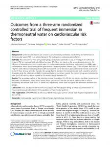
Figure 3: The bottom of the Pneumatic Arm
Figure 2: The top of the Pneumatic Arm
This configuration allows the top plate to have 2 degrees of freedom (Θ and Φ) relative to the bottom plates. Between the two plates are two inner tubes segments placed opposite each other. When the inner tubes inflate, they push the two plates away from each other, increasing the angle between them. Assuming the bottom plate is mounted horizontally, an inertial sensor is mounted on the top plate to measure angle relative to the bottom plate. With the two inner tubes mounted the way they are, the arm can only move in the theta direction; however, with more tubes, the arm can be converted to work in 3-dimensional space.
4 4.1
Control Feedback Loop Arduino Feedback
An Arduino Uno was used to control the arm, because of the ease of use, the variety of sensors associated with it, and the documentation. In order to find the angle of the top plate, the MPU-6050 accelerometer gyroscope was used. It was chosen because of it’s easy connection to an Arduino and the surplus of documentation and open source code associated with it. In order to collect the data from the MPU, Krodals data collection code [1] along with Geek Mom Projects’ filter[2] were used. These provided an accurate angle reading from the MPU as the arm moved. Once the angle data was collected, it was then fed through a PID controller using the Arduino PID library. The PID constants were found experimentally to get a rapid accurate response. It was found that as the P constant was increases, the possible error was reduced. This did, however, increase the time in which the valves are open for that loop. This allowed the system to achieve pressures it could not handle and break.
4.2
Pneumatic Control
Two three way two position valves were used in order to control the air flow from the source to the inner tube. The other position on the valve was connected to a two way
3
two position valve that either closed off the system, containing the air, or opened the flow to the open air. Series Solenoid Valve(2).jpg Series Solenoid Valve(2).jpg
Figure 4: This valve diagram shows the two states the three way two position valve can be in. When it is not powered (left section), it is set to vent. When it is connected to power (right section), it is ope to the pressure source. The three way two position valve was operated at 12VDC. The response time was 20ms. In order to control the 12VDC solenoid with an Arduino Uno, which outpust 5VDC, a simple circuit was constructed:
Figure 5: The driver circuit for a 12VDC solenoid using the digital outputs from an Arduino There was also a pressure regulator placed between the three way two position pneumatic valve and the inner tubes in order to lower the air flow into the the tubes. This allowed more variable control of the system rather than the bang-bang response that pneumatics usually exhibit.
5
PID to Solenoid interaction
The output of the PID was scaled such that it corresponded either to the amount of time in ms the bladder is open to the source or the air, depending on whether the output was positive or negative respectively. Any value below 20 ms was ignored as
4
it was lower than the solenoid minimum response time. In order to insure the angle was initialized on the IMU when the plates were parallel, both bladders were inflated evenly before the initialization code was run. i n t t a r g e t =0; c o n s t i n t valve_1_pres =1; c o n s t i n t valve_1_open =2; c o n s t i n t valve_2_pres =3; c o n s t i n t valve_2_open =4; d o u b l e S e t p o i n t , Output , I n p u t ; d o u b l e kp = . 5 , k i =1 ,kd ; PID myPID(& Input ,& Output ,& S e t p o i n t , kp , k i , kd , DIRECT) ; void setup ( ) { int error ; uint8_t c ; pinMode ( valve_1_pres , pinMode ( valve_1_open , pinMode ( valve_2_pres , pinMode ( valve_2_open ,
OUTPUT) ; OUTPUT) ; OUTPUT) ; OUTPUT) ;
S e r i a l . begin (19200) ; /∗ S e r i a l . p r i n t l n (F( " I n v e n S e n s e MPU−6050" ) ) ; S e r i a l . p r i n t l n (F( " June 2012 " ) ) ; ∗/ // I n i t i a l i z e t h e ’ Wire ’ c l a s s f o r t h e I2C−bus . Wire . b e g i n ( ) ; s o l e n o i d ( valve_1_pres , 4 0 ) ; s o l e n o i d ( valve_2_pres , 4 0 ) ; // Wait f o r t a r g e t p o s i t i o n w h i l e ( t a r g e t !=0) { d o u b l e t a r g e t _ i n p u t=S e r i a l . p a r s e I n t ( ) ; S e r i a l . print ( target_input ) ; t a r g e t=t a r g e t _ i n p u t ; } }
{
void loop ( ) Get_Angles ( ) ; // f l o a t a n g l e s [ ] = { last_x_angle , last_y_angle , l a s t _ z _ a n g l e } ; d o u b l e x_angle=l a s t _ x _ a n g l e ; // PID_pneumatic_control ( t a r g e t , x_angle ) ; S e t p o i n t=t a r g e t ; myPID . Compute ( ) ; i f ( Output 20) { s o l e n o i d ( valve_2_open , Output ) ; s o l e n o i d ( valve_1_pres , Output ) ; }
v o i d s o l e n o i d ( i n t valvenum , i n t i n t e r v a l ) { // s e t t h e v a l v e with t h e l e d S t a t e o f t h e v a r i a b l e : d i g i t a l W r i t e ( valvenum , HIGH) ; delay ( i n t e r v a l ) ; }}
6
d i g i t a l W r i t e ( valvenum ,LOW) ;
Results
As the purpose of this project was to explore the potential of variable compression based pneumatic actuation. In order to confirm or deny it, the steady state error, or the error left over when the arm stopped moving was measured. With the current PID parameters, the error was consistently within .34 degrees. Given the target angle was set to 6 degrees, the system had 5.66% of error. This level of error certainly proves the viability of the arm given it is the first prototype and still has a lot of inconsistencies in the system, such as weak seals.
7
Next Steps
The first step in the next iteration is to fix all of the shoddy self manufactured parts like the inner tube segments with stable industrial parts. This would greatly reinforce the system and allow it to operate at higher pressures and accuracy. After the system is consistent, the 2-dimensional model with be expanded into 3-dimensions. This would involve two more bladders mounted perpendicular to the original two. Two more pneumatic systems must also be included to control the air to these new additions. The control loop would be expanded to have another PID control for φ as well as θ. The mechanical system would remain very similar to how it is now. Another possible area for exploration would be to explore varying pressures with electronic pressure control valves. This would simplify the system by taking time out of the equation. Time based actuation was considered in order to explore a novel means of controlling pneumatic systems; however, the 20ms response time adds error into the system. Controlling the air in the bladders with pressure regulators would not only reduce error, but also simplify the control system.
6
References [1] Krodal, Arduino Playground: MPU-6050 Accelerometer + Gyro, Arduino, July 2013. [2] Debra, Geek Mom Projects: Gyroscopes and Accelerometers on a Chip, Geek Mom Projects, March 31, 2013. [3] Craig M. Goehler, B.S., M.S, DESIGN OF A HUMANOID SHOULDER-ELBOW COMPLEX, e University of Notre Dame, July 2007.
7