POSITIONING IN Wi-Fi NETWORKS Iliana Nikolaou1, Spyros Denazis2 1
Electrical Engineer and Computer Technology, University of Patras, Maizonos 231, 26222.Patras,
[email protected], +30-6973-243144, 2 Assistant Professor, Department of Electrical Engineer and Computer Technology, Panepistimioupoli, Kato Kastritsi, 26500, University of Patras,
[email protected], +30-2610-996478
Abstract – A widely used network such as the Wi-Fi can be used to provide a user with more services than just communication among devices: services that are related to the current position of the user, known as location based services. There are lots of techniques used in order to estimate a user’s position. In this paper, there is a description of the techniques that can be used in Wi-Fi networks and also an experimental part is presented, where some of these techniques are used to verify the prospective result and a satisfactory accuracy in an indoor and outdoor environment. Keywords Positioning techniques, Wi-Fi, Radio Fingerprinting, Empirical model, (k) Nearest Neighbour, Euclidean distance. Research Field Telecommunications and Networks.
I. INTRODUCTION Recent rise of wireless technology combined with the need for portability has led to the development and installation of wireless LANs and wireless devices. The use of wireless networks mainly, and Wi-Fi (802.11) in particular, raised a point on how it would be possible to extend the use of that network, so that they could provide the most services possible. As a result, nowadays, there are Wi-Fi systems, whose primer service is the position localization of the user. They are known as location-based systems, and they provide location-based services (LBS). Information provided to the user is related only to his position at an exact time period (real-time) and could be essential for services like the knowledge of another user’s position, gaining helpful information in public places, making everyday life easier at home, and of course it could be really meaningful for special needs people. There are a lot of techniques used to locate a user’s position, like CellID, TDOA , AOA , the fingerprint method ,RSSI , Hybrid methods , CGI and a
combination of these techniques. The efficiency of each technique consists of the best combination between the accuracy of the position estimation (the error made during localization) and the implementation cost, as accuracy improves in proportion to the increase of the cost. A combination of some of these techniques can also be used in order to achieve a better accuracy. There are some fundamental criteria with which positioning techniques are ordered. To start with, there are network-based techniques and client-based techniques. In the network-based case, the approach for the positioning is taking place at an access point and so the network manager is able to know the exact position of a terminal device and so the user’s position, while in the client-based approach, the positioning procedure takes place at the terminal device and only the user knows his/her own exact location. Positioning can take place during data transfer or during the control of transfer and so there are data transfer layer techniques and control layer techniques. There are also some techniques with additional needs in software or extra needs in hardware. The additional needs in hardware are usually expensive and that is why there is an effort to use the already existing WLANs for further purposes such as positioning. Finally, there are techniques which can be used in an indoor environment, in an outdoor environment and some of them which can be used in both environments but their accuracy differs from indoor to outdoor. Some networks, as it has already being mentioned, apart from their basic use can be used for a user’s positioning, as well. This usually happens by adding some extra hardware or software to the system. The networks in which positioning techniques can be implemented are separated in two categories. Terrestrial wireless networks and satellite networks. GSM/GPRS-UMTS, WLAN-WIMAX, and Bluetooth are some common terrestrial wireless networks where positioning can be applied to and GPS, CLONASS and Galileo are some satellite networks made for localizing a user’s position.
GSM/GPRS-UMTS are mainly used for outdoor positioning and the techniques that can be practiced on them are Cell ID (Cell IDentification), UL-TOA (UpLink Time Of Arrival), E-OTD (Enhanced Observed Time Difference), OTDOA (Observed Time Difference of Arrival) and A-GPS (Assisted GPS). Bluetooth is used for indoor positioning because of its limited range. Bluetooth systems use Received Signal Strength Indicator (RSSI) to find the location of a terminal device.
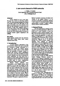
There are those based on radio beacon signals, those using time, those using signal strength and last the ones using angle. Schematically, they are shown in Figure 1.
GPS and satellite networks in general, are mostly used for outdoor environment positioning. They can be used for an indoor environment as well, but their use is not prevalent as its accuracy is much less than the outdoor environment one. In GPS, satellites transmit a signal with the exact place of the satellite and the time the signal was sent. The terminal device receives at least three signals like this, from three different satellites, and computes its position by using trilateration procedure. The positioning techniques used in Wi-Fi are discussed in details in Section II and after studying all those techniques there is a close-up choice in one of them in order to enquire about the way it can be used in practice to help a user locate himself. The experimental test bed, methodology, data collection and positioning procedure are presented in Section III. In Section IV there is a result analysis and some concluding remarks and in Section V the future work.
II.
TECHNIQUES USED IN Wi-Fi NETWORKS
Positioning techniques used in Wi-Fi can be networkbased or client-based. Network-based techniques need a mobile device, Access Points (APs), Reference Points (RPs) and a positioning server. The positioning server, can be accessed by a network manager only. It is informed about the exact position of each AP and RP. The collected data (ex. signal strength) is transferred to the positioning server from every RP and every device transfers the collected data to the positioning server. The positioning server compares them and informs the device user for his/her estimated position. At the client-based techniques, there is a device user, RPs and APs. The mobile device is notified about every AP position and stores the data it collects from every AP. For this purpose the device has special software equipment, the location determination server. The comparison described above now takes place in the terminal device. Techniques used in Wi-Fi are separated in four categories. The difference has to do with the way and the information they need in order to locate the user.
Figure 1 : Wi-Fi positioning techniques.
When using radio beacon techniques the user’s device scans the environment to find beacon signals from APs and its position is the position of the AP from which it receives the greatest signal strength. The user has a map of the APs being in his/her environment. A beacon signal is related to its transmitter in proportion to the MAC address sent, which is part of the beacon signal. In radio beacon signals, position estimation can happen either with predictive radio models or with radio fingerprinting. Predictive radio models usually take into account antenna types and their characteristics, and environment conditions. There are some predictive radio models like “war driving” [1] that use these data to estimate a user’s position. In radio fingerprinting approach, a radiomap with radioscannings is created. When a user wants to be located he/she just searches in the map to find the radioscanning - and so the place most identified with the data it receives in the place he/she wants to be located in. In this approach there is no need at all for a predictive radio model. Radio beacon techniques do not offer efficient accuracy. “War driving” for example provides accuracy 15-20m. Positioning in Wi-Fi systems can also happen using time. Positioning systems based in Time Difference of Arrival (TDoA) are systems that use the time difference of received signal and are the development of Time of Arrival (ToA) positioning systems. In ToA, the device receives the signal with the additional information of the time when the signal left AP and transforms time into distance. The device needs at least three APs to achieve desirable accuracy. At TDoA systems, AP transmits two signals at the same time at
different frequencies. Usually one of them is the beacon signal and the other can be an acoustic signal or an electromagnetic signal. As a result these signals reach the receiver different times. This time difference is transformed into distance. In order to find the user’s position this approach needs to take place three times from three different APs. The user’s position can then be found using the triangulation approach. The technique using signal angle is known as Angle of Arrival (AoA). It is mostly used for the outdoor environment but it can also be used for indoor environments. Nevertheless, it is not really used for indoor environments as it provides reduced accuracy comparing to other indoor positioning techniques. Generally, it measures the time difference for the signal to be transferred from two or more different elements of the same antenna. The most common way to find a user’s location in a Wi-Fi Network is positioning through the signal strength approach. Methods used in this approach are categorized in Figure 2.
Figure 2 : RSSI positioning techniques in Wi-Fi.
Positioning techniques in Wi-Fi networks can be based either on a propagation model or on an empirical model. The propagation model is connected with the degradation of the signal strength while drawing away from the AP and the empirical model relates to the collected data stored (signal strength) in a database. While a radio-signal transmits through the environment its signal strength is reduced. This signal loss can be translated into distance and can be modelled with models like hata-okumura model [14]. Having at least three distances from three different APs position can be computed with the triangulation approach. In Wi-Fi networks, radio-signal can be affected from multipath effects, dead spots, noise and interference and can get through reflection, diffraction, refraction and scattering. Moreover, the number of people in the environment, movements in the environment (people, doors etc) and antenna orientation can add some more effects in the signal distribution. In particular, people and movement in the environment can affect signal strength from 3 to 10 dBm and antenna orientation from 5 to 10 dBm. A typical propagation model, like the hata-okumura model, has an accuracy of 3 to 4m
for the indoor environment. On the other hand, the empirical model is based on the creation of a database. This database consists of signal strength values, which have been measured for a certain area. For this purpose, the area where positioning is taking place, is separated into smaller, practically similar, parts representing a grid. These parts are the reference points (RPs). Database creation, a procedure called mapping, is the creation of a map where signal strengths of each AP are stored for each part of the grid (RP). All this process is an offline process and is the first phase of the empirical model. It is the training phase of the fingerprinting approach. The database form is in Figure 3.
Figure 3 : Database form
The next phase is an online procedure and it is the actual positioning phase. Its purpose is to find the user’s position. In this phase, the terminal device measures received signal strength from each AP at the place where it is and wants to be located in. Those values are compared to the data of the database which was created in the training phase. The comparison is made with match (search and correspond) algorithms. This comparison procedure takes place in the positioning server which is in the terminal device in the client-based approach or somewhere else at the network (like in an AP) in the network-based approach. At the end the requested place is returned to the device user.
Figure 4 : The Online procedure
There are two algorithm categories used to match the real-time values to the database values. They are those based in probabilities and are called probabilistic methods and those based on deterministic methods. The probabilistic method approach, usually concludes to more detailed results, even though deterministic methods are the most commonly used because of the heavy computational power of probabilistic methods. The most widely probabilistic algorithms used are the Bayes rule, the Kernel method and the histogram method.
In the deterministic method approach, there are lots of algorithms that can be used. Some if them are Nearest Neighbour, K Nearest Neighbour, Viterbi-like algorithm, Naïve Bayes, Neural networks, Fuzzy logic, Subspace Techniques and Hidden Markov model techniques. In this paper Nearest Neighbour (NN) and k Nearest Neighbour (kNN) are used. In NN algorithm, the difference from the signal strength of each AP at a requested spot, to the signal strength of every spot of the database is measured. This difference is : n
Lq = (∑ | si − Si |q )1/ q
(1),
i =1
where si : signal strength of an AP and Si : signal strength of the same AP in the database. For q = 1: n
L1 = ∑ | si − Si |
(2),
i =1
which is Manhattan distance. For q=2: n
L2 = (∑ | si − Si |2 )1/ 2
(3),
i =1
which is Euclidean distance. Manhattan distance provides a shortly better accuracy but Euclidean distance is the most common distance used. At the end, Nearest Neighbor is the one with the least Lq. In kNN algorithm, instead of using the distance Lq from one Nearest Neighbor, there are k Nearest Neighbors and the final value to the user is their average value. K depends on the number of RPs. In particular, Lq distances are calculated and in the end there are k Nearest Neighbors. The values for each AP from each of the k distances are located in the database. Their average SS value for each AP is calculated and so at the end there is a combination like : (meanSS1,meanSS2,…..,meanSSn). The next step is for this combination to be transformed into one location. This happens by using the Lq type once more.
III. EXPERIMENTAL TEST BED The layout of the test bed for Wi-Fi signal analysis is shown in Figure 5.
Figure 5 : The test bed
The experimental procedure took place in the Electrical engineer and computer technology building, department of the Polytechnic school of the University of Patras. Specifically, half of the second floor of the central building was used. This part is rectangular and has a dimension of 50 * 20 meters, an area covering 1000m2. As can be seen in Figure 5, it includes a hallway from the one side to the other, some smaller hallways, several smaller rooms most of which are professors’ offices and some larger rooms which are classrooms or labs. Five APs (AP1…5) were used in this area as shown in Figure 5. Some of them were already there (AP2,AP3,AP4) and were used for the connection of the computers to the internet and for connection among computers. The other two APs (AP1,AP5) were placed there for the experimental procedure. The Wi-Fi APs were placed in specific spots so that the whole area was covered. The access points are 3COM type and their cover range is about 90 m at 1 Mbps and 30 m at 11 Mbps. To study signal propagation, we used a FujitsuSiemens Amilo L 7320 equipped with a NETGEAR WG111 adapter which receives the signal from the AP. The collected signal strength is in negative decibel meters (-dΒm) units. For the collection of the measurements the area was separated in 224 rectangulars of about the same size. 206 of them where used as the others are not at the building’s border. Each rectangular is considered to be a single spot. In each of them, we measure the received signal strength of each of the five APs so that the database is filled. When there is no signal from an AP the value of -110 dBm is used to express that at the database. All the measurements took place at about the same hours of the days except for weekends so that the conditions were considered to be about the same. After collecting all the measurements for the positioning procedure, the empirical model was used for the location positioning and in particular fingerprinting and the deterministic models by using NN and kNN algorithms as described in II. In kNN algorithm, k is four according to [2] this should be its value in relation to the number of RPs.
IV. EXPERIMENTAL VALUES USE AND ANALYSIS The next stage of the experimental procedure was the processing of the values of the database and the two algorithms used, in order to verify the experiment’s validity. The main purpose was the measurement of the accuracy of the two algorithms so as to verify the total accuracy they provide in positioning. For this purpose, the two algorithms were tested. The tests were made
using the values of the database and some extra values that were obtained for exactly this reason. Accuracy of the algorithms used In order to measure the accuracy of the two algorithms, all the values of the database were used. In particular, the two algorithms run 206 times as 206 are the spots of the map in the database. Each time, each algorithm was running having as entries the five values of the signal strength from each one of the 204 spots and the coordinates of a spot were returned. This spot was then compared to the spot which really corresponds to the signal strength values used in the algorithms. This comparison was made in the map, where the distance in spots becomes a distance in meters, knowing the scale of the map. After computing all the differences from the real spots to the returned spots in meters, their average for each algorithm was computed. The first algorithm, NN, has finally had an error of 2.018 meters and the second, kNN, has had an error of 3,379 meters. Those values are really accurate compared to the values suggested by the bibliography. Bibliography suggests that error values should be at least 2 meters. So the results for the accuracy can be considered as satisfactory. Moreover, we made a statistical data processing concerning the error of the two algorithms. The number of the returned spots is related to the distance error in meters. The results were put in the table in Figure 6.
Figure 6 : The number of the spots related to the distance from the real spot. From this table result these distributions : alg1
0-1,5m 1,6-3,2m 3,3-5,6m
alg2
0-1,5m 1,6-3,2m 3,3-5,6m 5,7-8,4m 8,5-10,6m 10,7-11,9m >12m
Figure 8 : kNN distribution
As can be seen in Figures 7 and 8, most of the values have minor divergence. Moreover, the number of spots with a large distance decreases as the distance error increases. In Figure 9 there is a comparison of the two distributions. The number of meausurements with less error is larger for NN than kNN. That is not true for the rest of the error values.
Figure 9 : NN AND kNN comparison
Experimental values use Except for the values which constitute the database, there were also some more measurements made – about fifty - after the completion of the database. Those measurements were made in the same period and at the same time of the day as those in the database, so as to retain the maintenance of the same conditions. Moreover, the coordinates of the extra spots were also known, except for the measurements, so that we would be able to test them. The measurements were tested in both NN and kNN algorithms so as to verify or not their proper working. The results were really favoring as, following the same procedure as before for computing the error, there was an error of 1.29 meters for the NN algorithm and 2.00 for the kNN.
5,7-8,4m 8,5-10,6m 10,7-11,9m >12m
Changes in values There are some areas at the map with some special characteristics. Areas like the hallways, and especially the big central hallway, or the region inside a room.
Figure 7 : NN distribution
and.
To start with, studying the measurement table, it is really easy to see that while leaving an AP the received signal strength reduces, as expected. The noticeable
thing here is that in a hallway this reduction is really slow. There is a slight difference in received signal strength from spot to spot while crossing the hallway. This is because there is an area where there are no obstacles like walls or people moving around. For the same reason it can be seen that, in most spots of the hallway, there is a received signal strength from each of the five APs. This happens mostly in this special area. Similar to hallway, in the inside of a room there are about the same conclusions. It is expected that while leaving an AP the received signal strength is reduced because of signal propagation. We studied the number of the received signal strength values being in a value range, so as to see where most of the values fluctuate. For this purpose the whole range of the values was separated into smaller ones and the results are in Figure 10 where the distribution of the values of the received signal strength can be seen.
kNN. As described before this is supposed to be a good accuracy (as min(accuracy)=2m).
V. FUTURE WORK This paper has discussed positioning in Wi-Fi Networks. Lots of issues related to this were analyzed, like all the methods that can be used and all the essentials for achieving a good accuracy as well. Yet, there are more things which could be further studied. Other issues, like the requirements needed in order to use more Wi-Fi positioning in outdoor environments, how to be able to reach a position localizing without always needing a new database, how to use this knowledge for further use (other networks), how to secure user’s privacy for his/her position and even more issues.
REFERENCES [1]
[2]
Figure 10 : Distribution of RSS
Outdoor environment (balcony) Finally, the perspective of positioning in an outdoor environment using a Wi-Fi network was examined. At the same floor that was used before, there is a balcony (Figure 11), whose shape was really interesting to study in our experiment.
[3]
[4]
[5]
[6] [7]
Figure 11 : The balcony
The database expanded with the values for the RSS of this new part of the map. Those values were used like the others in the previous phase of the experiment, to see if positioning can really work outdoors as well. The results were really promising. Almost all the spots were really located. This gives the two algorithms an accuracy of 3.018 meters for NN and 3,4 meters for
[8]
[9]
[10]
Anthony LaMarca, Jeff Hightower, Ian Smith, Sunny Consolvo, ”Self-Mapping in 802.11 Location Systems”, Intel Research Seattle. Binghao Li1, James Salter, Andrew G. Dempster and Chris Rizos, Indoor Positioning Techniques Based on Wireless LAN, School of Surveying and Spatial Information Systems, UNSW, Sydney, 2052, Australia School of Computer Science and Engineering, UNSW, Sydney, 2052, Australia. Ulf Rerrer, Location-awareness for a Serviceoriented Architecture using WLAN Positioning, Department of Computer Science Fuerstenallee 11, 33102 Paderborn Paderborn University, Germany. Paul Hii, Arkady Zaslavsky, “Improving Location Accuracy by Combining WLAN Positioning and Sensor Technology”, Monash University, 900 Dandenong Road Melbourne, Australia. Jonathan Wierenga, Peter Komisarczuk, “Location Based Services – SIMPLE”, NZNOG 2006, VUW March 22-24, 2006. Nicola Lenihan, “WLAN POSITIONING”, Univercity of Limerick. Z. Xiang, S. Song, J. Chen, H. Wang, J. Huang, X. Gao, “A wireless LANbased Indoor positioning technology”, IBM J. RES. & DEV. VOL. 48 NO. 5/6 SEPTEMBER/NOVEMBER 2004. R. Zhou, “Wireless Indoor Tracking System (WITS)”, Communication Systems/Computing Center, University of Freiburg, p.163-177. Anthony LaMarca, Jeff Hightower, Ian Smith, Sunny Consolvo, “Self-Mapping in 802.11 Location Systems”, Intel Research Seattle. Mark Paciga and Hanan Lutfiyya, Member, IEEE,” Herecast:An Open Infrastructure for LocationBased Services Using WiFi”.
[11]
[12]
[13]
[14]
[15]
[16]
[17]
[18]
[19]
[20] [21]
Marion Hermersdorf,” Location and Position Measurements”, Presentation for Licentiate course in measurement science and technology, 28.03.2007. Ciprian-Romeo ComUal, Jianghong Luo2, Alexander Haimovichl, Stuart Schwartz3, “Wireless Localization using Time Difference of Arrival in Narrow-Band Multipath Systems”, ECE Dept, CWCSPR Lab, New Jersey Institute of Technology, Newark, NJ, USA, Alcatel-Lucent Technologies, NJ, USA, EE Dept, Princeton University, Princeton, NJ, USA. Ryota Yamasaki, Atsushi Ogino, Tsuyoshi Tamaki, Takaki Uta, Naoto Matsuzawa and Takeshi Kato, “TDOA Location System for IEEE 802.11b WLAN”, Hitachi,Ltd., Central Research Laboratory, JAPAN Hitachi,Ltd., WirelessInfo Venture Company, JAPAN. Y. Okumura, E. Ohmori, T. Kawano, and K. Fukuda, "Field Strength and Its Variability in VHF and UHF Land-Mobile Radio Service," Review of the Electrical Communication Laboratory, 16, pp. 825-873, September-October, 1968. E. Elnahrawy, X. Li, R. P. Martin, “The Limits of Localization Using Signal Strength: A Comparative Study” in Proc First IEEE International Conference on Sensor and Ad hoc Communications and Networks (SECON), 2004. Binghao Li, Andrew G. Dempster, Joel Barnes, Chris Rizos, Donghang Li, “Probabilistic Algorithm to Support the Fingerprinting Method for CDMA Location”, School of Surveying & Spatial Information Systems University of New South Wales, Sydney, NSW 2052, Australia, Institute of Geomatics, Tsinghua University, Beijing, P.R. China. Teemu Roos, Petri Myllyma¨ki, Henry Tirri, Pauli Misikangas, and Juha Sieva¨nen, “A Probabilistic Approach to WLAN User Location Estimation”, International Journal of Wireless Information Networks, Vol. 9, No. 3, July 2002 (q 2002). Christos D. Desiniotis, “A Method to Improve Mobile Terminal Positioning Accuracy by Exploiting Historical Data”. P. Bahl, V. N. Padmanabhan, and A. Balachandran, “A Software System for Locating Mobile Users: Design, Evaluation, and Lessons”, Technical Report MSR-TR-2002-12, Microsoft Research, February 2000. ETSI TS 101 724 v8.1.0, “Location Services (LCS)”, April 2001. Y.-C. Cheng, Y. Chawathe, A. LaMarca, J. Krumm, “Accuracy Characterization for Metropolitan-scale Wi-Fi Localization” in Proc Third International Conference on Mobile Systems, Applications, and Services (MobiSys 2005), 2005.
[22]
[23]
[24]
[25]
[26]
[27]
[28]
[29]
M. Youssef, A. Agrawala, A. U. Shankar, “WLAN Location Determination via Clustering and Probability Distributions” in Proc IEEE PerCom2003, 2003. M. Youssef, A. Agrawala, “On the Optimality of WLAN Location Determination Systems”, Tech. Rep. UMIACS-TR 2003-29, and CS-TR 4459, University of Maryland. College Park,2003. R. Singh, M. Guainazzo, C.S. Regazzoni, “Location determination using WLAN in conjunction with GPS network (Global Positioning System)”, IEEE 59th Vehicular Technology Conference (Spring), 2004. C. Komar, C. Ersoy, T. Istanbul, “Location Tracking and Location Based Service Using IEEE 802.11 WLAN Infrastructure”, European Wireless, 2004. Kamol Kaemarungsi, Prashant Krishnamurthy, “Modeling of Indoor Positioning Systems Based on Location Fingerprinting”, IEEE Infocom, 2004. K. Kaemarungsi, “Design of indoor positioning systems based on location fingerprintingtechnique”, Doctoral Dissertation, University of Pittsburgh, 2005. Ekahau (2002), “Ekahau Positioning Engine 2.0: 802.11-based Wireless LAN positioning system”, An Ekahau Technology Document (http://www.ekahau.com), Nov 2002. Antti Kotanen, Marko Hännikäinen, Helena Leppäkoski, Timo D. Hämäläinen, “Positioning with IEEE 802.11b Wireless LAN”, Tampere University of Technology Institute of Digital and Computer Systems Korkeakoulunkatu 1, FIN33720 Tampere, Finland.