Power Line Communication Based Automation. System Using a Handheld Wi-Fi Device. Karthik Shivaram1, Nikhil Rajendra2, Kavi Mahesh3, Balasubramanya ...
2012 IEEE 16th International Symposium
2012 ISCE 1569550137
Power Line Communication Based Automation System Using a Handheld Wi-Fi Device Karthik Shivaram1 , Nikhil Rajendra2 , Kavi Mahesh3 , Balasubramanya Murthy K.N.3 , Padmavathy Jawahar3 University of Michigan, USA; 2 Stanford University, USA; 3 P.E.S. Institute of Technology, Bangalore, India
1
Abstract—An open source automation system for controlling electrical appliances using power line communication is presented here. Control messages are sent over Wi-Fi network from a Wi-Fi device to the micro-controller which then couples the messages to the power lines. Ubiquitous power lines are used as physical media to transmit data over 220V/50Hz signal to control appliances/equipment. The data from the microcontroller is coupled onto the power lines using a PLC (Power Line Communication) modem and DCSK (Differential Code Shift Keying) modulation technique is employed to transmit data. Each receiver unit consists of PLC modem plus microcontroller and can be connected anywhere in the power line network. The receivers have addresses assigned to them and only respond to the commands sent to them by the transmitter PLC modem. The receiver unit controls the flow of electricity to the socket. The entire system is devoid of a computer to save power and make it low cost. Use of open source hardware, Power Line Communication and micro-controller collectively reduce the cost of controlling appliances remotely. Keywords: Automation, PLC, DCSK, Open Sound Control, Wi-Fi, Open Source
example the systems which use Ethernet [4]. This escalates the cost and deters users from using such systems. Some of the other existing systems use archaic user interfaces which are neither natural nor intuitive, for example [5]. Also RF, Bluetooth based automation systems have limitations in being employed in areas which have concrete walls and surroundings [6],[7]. These problems necessitate a solution based on already existing infrastructure, one of which is using ubiquitous power lines, to overcome the limitations posed by the above technologies. The purpose of the system is to provide convenience to the user and also to reduce power consumption and save energy. This system requires no modification to the appliances, and it works for all appliances using electricity since electricity to the socket is controlled and not the appliance directly. The number of appliances needed to be controlled can be easily increased by increasing the range of addresses of the receiver units. Also the hardware and software used to build the system are licensed under open source license, unlike commercial systems which are proprietary in nature, thus lowering the cost of the system significantly.
I. I NTRODUCTION Automation essentially involves leveraging the power of technology to reduce the dependency on human presence and decision making for any process. It leverages different electronic equipment (either standalone or interlinked with appropriate applications) to control different parameters of any process. In these days of energy scarcity, it is prudent to save energy in every way possible. It is paramount to make such systems as easy to use as possible so that people can use their appliances in a smarter way to save energy. It also enables people to be more energy conscious by enabling them to have a real time status of electric appliances. Automation also helps reduce peak hour power consumption by enabling people to turn off appliances at will remotely. This facilitates a constant power supply by having varied pricing policies for different times of day and night. Aim of this project is to simplify the process of human-machine interaction through the use of a generic interaction system and to make things around us smarter and interactive. We envisaged building an interaction system that would allow us to interact with the physical/analog world. Earlier systems are mainly based on the use of telephone lines, such as a phone-based system for home automation using a hardware-based remote controller [1][2], and a personal computer [3]. The technologies used in existing automation systems have a number of limitations. Most of them require rewiring or connecting every appliance to a central unit, for
978-1-4673-1356-8/12/$31.00 ©2012 IEEE
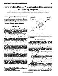
II. S YSTEM OVERVIEW A Wi-Fi enabled device is used as means of input. An iPod Touch is used for this purpose, which provides the user with a touch screen interface facilitating ease of use. A Wi-Fi network is first setup using a wireless router. The micro-controller connects to the wireless router through an Ethernet interface card. The Ethernet interface card and the micro-controller communicate over a Serial Peripheral Interface (SPI) bus. An application on the device consists of 3 buttons and 1 slider and enables us to send messages in Open Sound Control format. OSC (Open Sound Control) protocol is used to communicate between the iPod Touch and the micro- controller over a Wi-Fi network. When a user presses a particular button, specific messages are sent over the Wi-Fi network to the micro-controller which decodes the messages. The microcontroller converts these messages into simple control signals. The commands sent by the micro-controller to switch ON/OFF an appliance are not sent directly to the appliance, but rather these commands are broadcasted over the power lines using a Power Line Communication (PLC) transmitter. The microcontroller sends data to the PLC modem using UART protocol. Each end appliance has a PLC receiver plus micro-controller combination to listen to these commands, if the commands are
1
Figure 1.
System Block Diagram
intended to the corresponding appliance; it switches ON/OFF the appliance.
controls the behavior of the appliance. It also implements a software serial interface that allows it to communicate with and control the IT800D over the UART Host Interface.
III. P OWER L INE C OMMUNICATION (PLC) Power Line Communication is a technology which uses power lines as physical media for data transmission. PLC offers a no new wires solution because the infrastructure has already been established. PLC modems are used for transmitting data at a rapid speed through a power line in a house, an office, a building, and a factory, etc. Here, the existing alternating current (AC) power wires serve as a transmission medium by which information is relayed from a transmitter or control station to one or more receivers.
Figure 3.
A. PLC Modem description
UART
IT800D - The IT800D is a system on chip solution optimally designed to provide the best performance over the Power Line medium. PLC capabilities are added to the modem by integrating the IT800D into the modem circuitry. The IT800D handles the channel access on behalf of the modem, in addition to handling the entire communication over the power line. The PLC modem can be configured with various communication parameters through a programmable interface [8]. Analog Front End and Line Coupler - It sits between the IT800D and the physical network, connecting the device to the physical network medium (the power line). The AFE includes reception and transmission paths, with the required filtering and amplification. The Line Coupler couples the data to the power line. Power Supply - The power supply is a separate block, providing the required power to the IT800D and AFE. B. Modulation
Figure 2.
DCSK (Differential Code Shift Keying) modulation technique is known for its extreme robustness and belongs to the family of spread spectrum modulation technologies. Spread spectrum modulation is a technique in which a signal is transmitted on a bandwidth considerably larger than the frequency content of the original information [9]. Spread spectrum modulations provide many advantages: they are less susceptible to narrowband and burst noises, able to work when the signal level is lower than the noise level (negative SNR). They are
PLC Modem block diagram
Application Circuitry - It contains the relay circuit which provides the interface for connecting the appliance. Host - It is typically implemented using a general-purpose simple micro-controller; a Atmega 328 in this case. The Host
2
also less susceptible to multi-path fading, signals arriving via different routes, and impedance modulation. A communication medium such as the AC Power Line may be corrupted by fast fading, unpredictable amplitude and phase distortion and additive noise. In addition, communication channels may be subjected to unpredictable time varying jamming and narrowband interference. In order to transmit digital data over such channels it is preferable to use as wide a bandwidth as possible for transmission of the data. This is achieved using spread spectrum techniques; in particular a type of spread spectrum called “Differential Code Shift Keying” is used for the modulation technique [10]. DCSK modulates the symbol by cyclic shifting of the basic symbol in the transmitter, and detection of the shift in the receiver. The first picture in figure 4 shows the original none shifted symbol, which may also represent a ‘0000’ information. The second and third picture in figure 4 (below) demonstrate modulated symbols that are created from the original symbol by cyclic shift according to the data value.
Figure 4.
to send control commands to the micro controller over the Wi-Fi network [11]. Structure of OSC content The basic unit of Open Sound Control data is a message. This message contains a symbolic address and message name, and any amount of binary data. Entities within a system (network) are addressed individually by an open-ended URLstyle symbolic naming scheme that includes a powerful pattern matching language to specify multiple recipients of a single message. OSC streams are sequences of frames (also referred to as ‘bundles’) defined with respect to a point in time called a timetag. A bundle contains a number of messages, each of which represent the state of a sub-stream at the enclosing reference timetag. The sub-streams are labeled with a human-readable character string called an address. OSC bundle timestamps can be used to recover the correct order of the packets at the receiving end. The size of an OSC packet is always a multiple of 4.
DCSK Modulation Figure 5.
DCSK is spectrum modulation technology that enables extremely robust Power Line Communication. The features of DCSK which make it one of the best technologies for Power Line communication are as follows: Resistance to pulse noise, Resistance to linear and non-linear distortion, Adaptive operation handles fast variations in medium characteristics, Resistance to synchronization errors & timing jitters, Fast recovery from severe fade or jamming.
OSC Structure Format
The comparison below is provided to give a perspective of how the OSC message format compares with message formats for MIDI and XML. OSC’s advantages include interoperability, accuracy, flexibility, enhanced organization and documentation. Efficiency, low cost and reliability of this new protocol make it a potential replacement for current technology. iOSC is a remote control application that uses the OSC (Open Sound Control) protocol encodings for integers, real numbers and text. Using the OSC protocol over the device‘s built-in WiFi connection, the OSC application communicates with other compatible hardware and software nodes over the network. Comparison of message formats of OSC vs. MIDI vs. XML OSC: /server/slider1/3 f 0.25 MIDI: 0x01 0x00 0x03 0x32 XML: 0.25
IV. O PEN S OUND C ONTROL Open Sound Control (OSC) is a protocol for real time communication between computers, sound synthesizers and other multimedia devices which are optimized for networking technology. OSC is touted as the next generation replacement for the MIDI format. OSC is a transport independent protocol which means that it is a format for data that can be carried across a variety of networking technologies like USB, Firewire and Ethernet. OSC offers bandwidth greater than 10mbps compared to MIDI‘s 31.25kbps. We have used OSC protocol
3
Figure shows the screenshot of iPod interface consisting of 3 buttons and a slider for controlling appliances. The program residing on the micro-controller is designed to decode the encoded OSC messages from the iPod. if( osc.available() ) { if(!strcmp( recMes.getAddress(0) ,topAddress ) ) { if(!strcmp( recMes.getAddress(1) ,subAddress[0] ) ) { if(recMes.getArgInt(0) == 1) { digitalWrite(RED\_LED, HIGH);}}}} In this code snippet, the osc.available() function is used to check for availability of OSC messages, the topaddress and subaddress of the OSC message is compared. If both the address match then the integer value is checked to determine whether to switch ON/OFF the appliance. The code on the micro controller is just 6.2kB in size. The micro-controller converts the decoded OSC messages into control signals to turn ON/OFF specified appliance. The micro-controller and the PLC modem communicate over UART.
V. I MPLEMENTATION An iPod touch is used for sending control commands to the micro-controller over Wi-Fi using OSC protocol. OSC can be used to encode integers, real numbers and text. Using the OSC protocol over the device‘s built-in Wi-Fi connection, the OSC application communicates with other compatible hardware and software nodes over the network. Any client which supports the OSC format could be used, for example Mrmr, Touch OSC, OSCemote. The iOSC application on the iPod allows us to send customized messages in the OSC format over Wi-Fi. The interface consists of three buttons (to send high and low values) and a slider for pulse width modulation.The sliders can be used for varying brightness of light bulbs or for controlling the speed of fans. This application will convert the button presses into predetermined OSC messages and will append specific IP and port addresses to the message. A router is used in the setup to host a local wireless network. The Ethernet interface card connected to the microcontroller is initialized to a specific IP address so that it is in the same network as the iPod. The IP address and port addresses are set to be the same in both Ethernet interface card and in the iOSC application. byte serverMac[] = { 0xDE, 0xAD, 0xBE, 0xEF, 0xFE, 0xED }; byte serverIp[] = { 192, 168, 1, 104 }; int serverPort = 10000; Ethernet.begin(serverMac ,serverIp); Here the MAC, IP and Port address values are defined and the Ethernet interface card is initialized using the Ethernet.begin() function. button1 button2 button3 slider1
Message /server/yelled /server/grnled /server/redled /server/pwmled
Type int int int int
On 1 1 1 max:255
Off 0 0 0 min:0
Figure 7.
The micro-controller sends the commands serially to the master PLC modem. Serial.println("0"); delay(500); Serial.println("0"); Here the micro-controller sends data to the PLC modem over UART interface using the Serial.println() function. The data is sent twice to the PLC modem by retransmitting the same data with a delay of 500 milisecond. This modem broadcasts the control signals through the Power Lines. At the receiving end, each appliance has a PLC modem. This PLC modem listens over the Power Lines for any control signals. If a PLC control signal is available, the modem sends it to the receiving micro-controller. The micro-controller checks if the command was intended for this appliance, if not simply ignores it. If the command was for that particular appliance, the microcontroller switches ON or OFF the relay connecting the appliance. while (Serial.available() > 0)
Table I PARTS SETTING
Figure 6.
Actual picture of the PLC modem used in our setup
Screenshot of iPod Touch interface
4
{ cmd = Serial.read(); switch (cmd) { case ’0’: { digitalWrite(RELAY_PIN, HIGH); digitalWrite(PIN, HIGH); break; }}} Here is a code snippet of the receiving micro-controller, where first the availability of serial data is checked and then read into a register. The received data is compared with the standard address of the unit and correspondingly the relay unit is switched ON/OFF.
Figure 10.
Figure 8.
Figure 9.
VI. A PPLICATIONS Agriculture, Soil monitoring, Weather station reporting, Remote data acquisition, Power line fault monitoring, Home and industrial automation, Home networking, Automatic meter reading systems, Real time monitoring of energy consumption, Building management solutions. Use of the system shown above for the implementation of a particular application is explained briefly- The increase in public demand for energy creates the need for Energy Saving and Energy Management procedures. Utilities can lower cost by reading meters remotely, charging according to time of use or according to level of power used, automating power failure recovery and lowering the investments in new power stations. Utilities can increase revenue by offering more services to the customers (besides just offering power). In some areas of the world, 30% and more of the electricity is stolen. AMR/AMM is used to detect electricity looting. Real time remote monitoring of energy consumption: Every socket in a particular environment could be monitored for energy consumption, and the data could be transmitted over the power lines by using PLCs and then the data could be uploaded onto the web for visualization. Access to the data could be enabled using mobile devices so that the user knows which appliance is consuming the maximum power and could also provide data to the electricity company about the electricity consumption patterns in various homes/residences.
Transmitter Schematic
VII. F UTURE A DVANCEMENTS /E NHANCEMENTS
Receiver Schematic •
• • • • • • •
Setup
The use of a computer is avoided leading to lower power consumption and reduced costs. No rewiring required, uses existing power lines. Modularity Size, compactness. Supports for upto 256 appliances/devices Ease of installation Open source hardware
•
• •
5
The transmitter unit can be made portable and compact by incorporating a battery pack, Wi-Fi interface card instead of Ethernet to the existing set-up. A java based interface could be implemented to incorporate the addresses to increase the number of receiver units thereby controlling more number appliances. One can use advanced communication interface (GPRS, EGPRS, UMTS) for extended range of control. The entire setup could be miniaturized using SMD components and multiple layer PCBs. The resulting size will
•
be small enough to be fixed inside a switch board. High speed Power Line modems could be used for last mile broadband connectivity. Implementation of PLC-Zigbee Hybrid combination could further enhance the functionality of the system.
[9]
Shwehdi, M.H.; Khan, A.Z.; , "A power line data communication interface using spread spectrum technology in home automation," Power Delivery, IEEE Transactions on , vol.11, no.3, pp.1232-1237, Jul 1996 doi: 10.1109/61.517476 [10] Raphaeli, D.; , “Spread Spectrum Communication System Utilizing Differential Code Shift Keying”, Itran Communications, Israel [11] Schmeder, A; Freed, A; and Wessel,D; , “Features and Future of Open Sound Control version 1.1 for NIME”, Center for New Music and Audio Technologies (CNMAT), UC Berkeley
VIII. R ESULTS AND CONCLUSION The system was tested using a Power Line transmitter and two receivers connected to appliances kept at different locations but within the same electric network. The appliances were controlled by sending specific commands to trigger the relays which were the switch link in the circuit. The signals do not get transmitted through the MCB so the signals sent from one house don’t interfere with that of the neighbor’s. The response to commands sent by the iPod interface had a lag of 0.6 to 1 second. Some of the challenges faced during the course of implementation of the system. • Porting the decoding program of OSC messages onto the microcontroller. • Reliability of Power Line communication system • To improve the reliability of data reaching the end receiver redundancy was introduced by sending the data twice from the Power Line transmitter. • The noise on the Power Line and interference if beyond a threshold could corrupt the data being transmitted on the Power Line. • The range of control primarily depends upon the range of the Wi-Fi router as the range of the PLC modem has been validated to be 300m in a straight-line environment. The system was extensively tested for various conditions/cases such as AC power, UPS and no power and practical conditions were simulated artificially; for example resetting automatically from no power state. The system uses Power Line as a physical media for communication so in spite of no activity on the Power Line data was being transferred reliably. R EFERENCES [1] Wong, E.M.C.; , "A phone-based remote controller for home and office automation," Consumer Electronics, IEEE Transactions on , vol.40, no.1, pp.28-34, Feb 1994 doi: 10.1109/30.273654 [2] Coskun, I.; Ardam, H.; , "A remote controller for home and office appliances by telephone," Consumer Electronics, IEEE Transactions on , vol.44, no.4, pp.1291-1297, Nov 1998 doi: 10.1109/30.735829 [3] Koyuncu, B.; , "PC remote control of appliances by using telephone lines," Consumer Electronics, IEEE Transactions on , vol.41, no.1, pp.201-209, Feb 1995 doi: 10.1109/30.370328 [4] Zhang X.; Sun J.; Zhou L., “Development of an Internet Home Automation System using Java and Dynamic DNS Service”, Sixth International Conference on Parallel and Distributed Computing, Applications and Technologies (PDCAT ’05) 0-7695-2405-2/05 [5] Rosendahl, A.; Hampe, J. Felix and Botterweck, G., “Mobile Home Automation-Merging Mobile Value Added Services and Home Automation Technologies”, Sixth International Conference on the Management of Mobile Business (ICMB 2007) 0-760695-2803-1/07 [6] Sriskanthan N.; Tam, F.; Karande, A. “Bluetooth based home automation system”, Microprocessors and Microsystems 26, 2002, pp 281-289. [7] Poole, I. “What exactly is Zigbee?”, Communications Engineer, Volume 2. Issue 4, August-September 2004, pp 44-45. [8] Yitran IT800D Power Line Communication Modem Data Sheet
6