expectation is that precise visual pattern specification will firstly enable clear ...
pattern users), and secondly enable CASE tool support for design patterns,.
Precise Visual Specification of Design Patterns Anthony Lauder and Stuart Kent Division of Computing University of Brighton, Lewes Road, Brighton, UK
[email protected] fax: +44 (0) 1273 642405, tel: +44 (0) 1273 642032
[email protected] fax: +44 (0) 1273 642405, tel: +44 (0) 1273 642494
Abstract. There has been substantial recent interest in captured design expertise expressed as design patterns. Prevalent descriptions of these design patterns suffer from two demerits. Firstly, they capture specific instances of pattern deployment, rather than the essential pattern itself, thus the spirit of the pattern is often lost in the superfluous details of the specific instances described. Secondly, existing pattern descriptions rely upon relatively informal diagrammatic notations supplemented with natural language annotations. This can result in imprecision and ambiguity. This paper addresses these problems by separating the specification of patterns into three models (role, type, and class). The most abstract (role-centric) model presents patterns in their purest form, capturing their essential spirit without deleterious detail. A role-model is refined by a type-model (adding usually-domain-specific constraints), which is further refined by a class-model (forming a concrete deployment). We utilise recent advances in visual modelling notation to achieve greater precision without resorting to obtuse mathematical symbols. A set-oriented view of state, operations, and instances is adopted, permitting their abstract presentation in models via this visual notation. This paper utilises these ideas in the unambiguous specification of a selection of prominent design patterns. The expectation is that precise visual pattern specification will firstly enable clear communication between domain experts and pattern writers (and ultimately pattern users), and secondly enable CASE tool support for design patterns, permitting the designer (pattern user) to operate at a higher level of abstraction without ambiguity.
1
Introduction
1.1 Design Patterns Design patterns capture the distilled experience of expert designers. Patterns are not invented, rather they are “mined” from existing systems. The mining process involves the extraction of designs from a number of systems, looking for “patterns” in designs across those systems. The expectation is that expert designers will have utilised similar proven designs to resolve similar problems in different application domains. Patterns document these proven designs, removing domain-specific features thus specifying only their essential aspects. A documented pattern, then, is deployable in a E. Jul (Ed.): ECOOP’98, LNCS 1445, pp. 114-134, 1998. c Springer-Verlag Berlin Heidelberg 1998
Precise Visual Specification of Design Patterns
115
new domain via the addition of domain-specific features to the pattern’s essential aspects. There exists a rapidly expanding body of literature documenting important design patterns [3], [5], [8], [14], [20]. The most influential of these is the “Gang of Four” text [20] (hereafter referred to as GoF) which details twenty-three fundamental patterns. 1.2 Impure Pattern Modelling Current pattern literature (including GoF) tends to present each pattern in terms of a specific implementation of that pattern. The intent is that the reader should be able to glean from the specific implementation the essential elements (or “spirit”) of the pattern, rejecting those aspects which are relevant only to the example presented. It is our belief that, although examples of pattern deployment are valuable in their own right, the essential spirit of a pattern is often lost in the superfluous details of a specific implementation. It is our assertion that example-based revelation is enhanced by the addition of precise visual specifications which retain that essential spirit. 1.3 Pure Pattern Modelling In this paper we propose a three-model presentation of patterns. The first model (the role-model) is the most abstract and depicts only the essential spirit of the pattern, excluding inessential application-domain-specific details. The second model (the typemodel) constrains the role-model with abstract state and operation interfaces forming a (usually domain-specific) refinement of the pattern. The final model (the class-model) realises the type-model, thus deploying the underlying pattern in terms of concrete classes. 1.4 Formal Modelling A model may be viewed as a composition of constraints. Prevalent modelling notations such as Booch [2], OML [7], OMT [16], and UML [17] are not sufficiently expressive in the constraints they can represent graphically. Consequently, the designer is forced to supplement modelling diagrams with constraints specified textually. This supplementary text is typically expressed as natural language narrative. The formal methods community has argued that this combination of existing diagrammatic notations and natural language text often results in specifications which are imprecise and, therefore, ambiguous. Consequently, formal-methods mathematical notations such as Z [1] and VDM [11] have been developed to add precision to specifications. A number of contemporary object-oriented methodologies such as Syntropy [4] and Catalysis [6] replace natural language with these mathematical notations to supplement diagrammatic models with precise constraint specifications. Formal methods research has clearly provided a strong theoretical foundation for precise specification. Research in formal methods, though, has been lacking in the area of approachability. In particular, there has been the underlying assumption that obtuse mathematical notations are necessary to achieve precision, thus alienating all
116
Anthony Lauder and Stuart Kent
but the most mathematically mature modellers. To address this problem, UML has recently been supplemented with the Object Constraint Language (OCL), a textual notation which has been developed “… to fill this gap. It is a formal language that remains easy to read and write” [19]. 1.5 Visual Pattern Modelling OCL is an important advance towards approachability. The notation, however, is founded upon the assumption that “a graphical model … is not enough for a precise and unambiguous specification” [19]. That is, there is the underlying assumption that constraints are necessarily specified textually. Recent work by Kent [12], however, dispels this assumption by presenting an approachable diagrammatic notation with which constraints are specifiable visually with no loss of precision. Kent’s notation, termed Constraint Diagrams is compatible with, and thus may supplement existing and less-expressive diagrammatic modelling notations: [2], [6], [7], [16], [17]. Note that a separate research effort is providing the formal semantics of the Constraint Diagram notation. Current pattern literature supports diagrammatic pattern specifications with textual supplements. These textual supplements serve two purposes. The first is to reinforce diagrams with supporting information. Examples of this are descriptions of motivation for, consequences of using and known uses of the pattern. This supporting information forms a crucial and intrinsic part of any pattern description and must be retained, since a description of patterns without this supporting information would simply be an architecture without context. The second purpose of textual supplements, though, is to disambiguate pattern diagrams. For example, GoF presents participants and collaborations narrative to add precision and expressiveness to their structure diagram. That is, these narrative sections recognise that the diagrams presented are both ambiguous and inexpressive. We will demonstrate throughout this paper that with constraint diagram notation we are able to depict unambiguous and expressive pattern structure in a visual form, supplemented with only supporting textual information (i.e. excluding the need for narrative to disambiguate the diagrams). In this paper we utilise constraint diagrams in combination with UML for the unambiguous specification of selected design patterns. 1.6 Selected Patterns GoF segregates patterns into three categories: Creational Patterns (which create objects), Structural Patterns (which form composite classes and objects), and Behavioural Patterns (which partition algorithms across collaborating objects). This paper focuses upon the specification of one design pattern from each category. More specifically: Abstract Factory (Creational), Composite (Structural), and Observer (Behavioural). The first of these patterns (AbstractFactory) is the focus of the main body of the paper. The remaining patterns (Composite and Observer) are presented in the appendix.
Precise Visual Specification of Design Patterns
2
117
Gang-of-Four Presentation of Abstract Factory Pattern
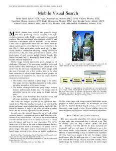
The intent of the abstract factory creational design pattern is to “Provide an interface for creating families of related or dependent objects without specifying their concrete classes” [9] GoF presents the AbstractFactory as the single diagram, reproduced in figure 1.
Fig. 1. Gang-of-Four Presentation of Abstract Factory Pattern Client
AbstractFactory CreateProductA()
AbstractProductA
CreateProductB()
ConcreteProductA2 ConcreteFactory1
ConcreteProductA1
ConcreteFactory2
CreateProductA()
CreateProductA()
CreateProductB()
CreateProductB()
AbstractProductB
ConcreteProductB2
ConcreteProductB1
2.1 GoF Impurity The GoF presentation of Abstract Factory, as in figure 1, suffers from the major demerit that it actually represents a single deployment of the abstract factory pattern rather than the generalised pattern itself. More specifically, the pattern as presented defines specific operation interfaces for the AbstractFactory class (CreateProductA and CreateProductB) which are realised by fixed concrete classes (ConcreteFactory1 and ConcreteFactory2). In addition, two specific abstract product classes are depicted (AbstractProductA and AbstractProductB), each further specialised by concrete product classes. This significantly reduces the general applicability of the pattern as specified. In practise, other deployments of the pattern would require different numbers of and different properties for these types and operations. The general pattern, then, is not expressed with purity in figure 1. 2.2 Collections As Named Pairs We believe that a major cause of the lack of purity in GoF pattern diagrams is the tendancy to imply collections via the expression of fixed numbers of named instances or classes. For example, turning to figure 1 there are two concrete factory classes, and two abstract product classes each implemented by two concrete product classes. This is unsatisfactory since it forces the diagram to misrepresent quantities in the pattern
118
Anthony Lauder and Stuart Kent
(by premature commitment to a cardinality of two), and forces premature commitment to names for each of those collection elements (ProductA1, ProductA2 etc). Similar premature commitments to named specific quantities proliferate in the GoF pattern descriptions. The behaviour of the Observer pattern, for example, is depicted via a sequence diagram depicting two concrete observer instances, whereas in reality the pattern permits any arbitrary number of observers. Neither the commitment to fixed quantities, nor the commitment to element names such as ProductA1 and ProductA2, adds any semantic value to the pattern whatsoever. Indeed, the presence of these commitments actually detracts from the semantics of the essential spirit of the pattern, since they inaccurately depict constrained generality. Consequently, it would be almost impossible to take the pattern as presented in figure 1 and specify differentially a divergent deployment of that pattern. 2.3 Anonymous Arbitrary Collections What we actually require, to express a pattern in its full generality (i.e. purity), is a way to express and reason about collections without premature commitment to either cardinality (i.e. quantity) or naming of collection members. This, we assert, would permit direct differential specification (refinement) of the pattern into ad-hoc deployments. 2.4 Constraint Diagrams We choose to represent collections in terms of sets, upon which we may specify constraints applying to set members. Sets enable us to talk about collections generally (without premature commitment to cardinality or naming), and constraints enable us to talk about collections precisely. Since constraint diagrams focus upon the specification of constrained sets and set members, they constitute the ideal notation with which to depict anonymous arbitrary collections. Constraint diagram notation is detailed initially in [12] and [13], and in an upcoming series of papers which explore both the syntax and the semantics of the notation. In the current paper we utilise a number of recent enhancements to the notation documented in the early papers. Below, we provide a brief introduction to the notation, including the recent enhancements we have utilised. Constraint diagrams depict sets as Venn diagrams. An arbitrary member of a set is depicted via a dot within or on the edge of the set (see figure 2). Two unconnected dots are definitely distinct. Two dots connected via a spring indicates that the dots do not necessarily represent distinct set elements (i.e. they may be the same element). Two dots connected via a strut represent alternative positions for a single element (i.e. an element may reside in only one of the positions represented by the connected dots at any time).
Precise Visual Specification of Design Patterns
119
A directed arc represents a traversable relationship between sets and set members (see figure 3). Fig. 2. Set Membership paperback a
b
‘a’, 'b', and ‘c’ are distinct arbitrary set members. ‘d’ and ‘e’ are not-necessarily-distinct arbitrary set members 'f', 'g', and 'h' represent a single element which may exist in one, and only one, of three positions at a given time.
c
d
e
f
g h out of print
Fig. 3. Navigable Relationships publication
title
title Each publication has a title
2.5 UML In this paper we utilise constraint diagrams in conjunction with UML notation. In UML “a class is drawn as a solid-outline rectangle with 3 compartments separated by horizontal lines. The top compartment holds the class name and other general properties of the class (including stereotype; the middle list compartment holds a list of attributes; the bottom list compartment holds a list of operations” [17]. Figure 4 gives an example, depicting a publication from the perspective of a publisher: Fig. 4. UML Class Diagram General Properties (incl Name)
publication
State (Attributes)
Title : string Authors : list ISBN : string Body : text
Behaviour (Operations)
Sell( Copies, Client ); Print( Copies );
Bill( Copies,Client,this ); Send( Copies,Client, this ); for(int i=0;i!=Copies;i++) printer
>
AbstractFactory
AbstractProduct >
>
>
>
>
AbstractFactory
CreateProductA (): AbstractProductA CreateProductB ():AbstractProductB
> AbstractProductB
> AbstractProductA
> >
3.7 Class-Model as refinement of Type-Model Figure 9 could be flattened (by synthesis) into the original type-model depicted in figure 1. Since both models are semantically equivalent this would be a purely cosmetic step and is unnecessary for the purposes of this paper. Consequently, we omit this step here. It is similarly easy to visualise how the concrete (class-model)
124
Anthony Lauder and Stuart Kent
deployment of the abstract factory pattern, as depicted in figure 7 may be re-expressed as a refinement of the type-model in figure 9. Again, since this is a trivial step, we omit it here. In practise, a CASE tool supporting patterns would benefit from accommodating the flattening of derived patterns via synthesis (e.g. flattening figure 9 back to figure 1), since a valid criticism of the refinement approach is that the user can become overwhelmed by the number of levels of refinement and their interconnections. In other words, although the layering approach is valuable for building models, it is not necessarily the best approach for presenting them in an ultimate (or even intermediate) design. Tool support would presumably permit traceability between layered and synthesised models, with a mechanism for easily switching between them. 3.8 Summary of Three-Model Specification In summary, we have argued that purity in pattern description may be achieved by employing a layered three-model specification. The first layer (the role-model) expresses the pattern purely in terms of highly abstract state and highly abstract behavioural semantics, forming a constraint set which captures the essential spirit of the pattern without dilution in non-essential (application-domain specific) details. The middle level (the type-model) refines the role-model adding usually-domain-specific refinements to the abstract state and semantics, and concrete syntax for operations described by the abstract semantics. The final layer (class-model) deploys the typemodel in application-specific terms via the specification of concrete state (attributes) and concrete semantics (method implementation), which realise the abstract state and abstract semantics respectively. This layering of models is summarised in figure 10. Fig. 10. Three-Model Layering
RoleName Abstract State Structure
Abstract Behavioural Semantics Abstract Instances
TypeName
Refined Abstract State Structure Refined Abstract Behavioural Semantics + Operation Interfaces Refined Abstract Instances
>
ClassName
Concrete State Structure Concrete Behavioural Semantics (Method Implementations) Instances
Precise Visual Specification of Design Patterns
4
125
Dynamics of AbstractFactory
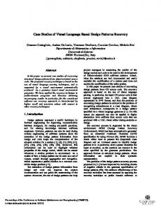
The previous section focused upon purity of specification by presenting patterns at multiple levels of abstraction, each refining the level above it. The focus was very much on the static properties of patterns. Our attention now turns to dynamic behaviour. 4.1 Sequence Diagrams UML permits two overlapping forms of behavioural specification: Sequence diagrams and collaboration diagrams. The former presents time as a separate dimension but loses depiction of relationships between collaborators, whereas the latter preserves relationships but the time dimension. Interestingly, GoF does not present AbstractFactory behaviour diagrammatically. It does, however present the behaviour of other patterns via sequence diagrams. We continue that tradition here, although we present a slightly modified form of sequence diagram, which combines the benefits of UML sequence diagrams and collaboration diagrams by bounding sequence diagrams with pre- and post-conditions expressed as constraint diagrams. That is, our diagrams show time as a separate dimension, yet still preserve relationships between collaborators. We present our diagrams in flat twodimensional form. It is possible, however, to provide a three-dimensional rendering where each constraint diagram is tilted away into a three-dimensional image, with the time dimension running through the tilted constraint diagrams thus connecting them. This would be particularly advantageous with appropriate CASE tool support. Threedimensional constraint diagram modelling is investigated further in [10]. 4.2 Class-Model Sequence Diagrams Typically, one or more sequence diagrams are drawn for each method in a concrete class-model. For example, we present a sequence diagram specification of ConcreteFactory1::CreateProductA() in figure 11. Fig. 11. Class-Model-Level Sequence Diagram Pre ConcreteFactory1
ConcreteProductA1
CreateProductA():ConcreteProductA1
CreateProductA()
new()
Post
ConcreteFactory1 CreateProductA():ConcreteProductA1
ConcreteProductA1
126
Anthony Lauder and Stuart Kent
Let us examine figure 11 in detail. An instance of ConcreteFactory1 (depicted by a dot in the abstract instances compartment) is the target of the invoked operation (CreateProductA1). The invoked operation calls the ‘new()’ operation of ConcreteProductA1 to create an instance of that class. The created product is returned back to the client. 4.3 Type-Model Sequence Diagrams Although it is useful to present sequence diagrams for all class-model methods, we can achieve a much cleaner view of behaviour by shifting abstract semantics up to the type-model and specifying in class-model sequence diagrams only method-specific variants of the abstract semantics. For example, all realisations of the operation AbstractFactory::CreateProductA() must respect a shared semantics, which rightly belongs as an abstract behavioural specification in the type-model. Thus, we can place shared abstract behaviour in sequence diagrams at the type-model level. An example of this is shown in figure 12. Fig. 12. Type-Model-Level Sequence Diagram Pre AbstractFactory CreateProductA()
CreateProductA()
AbstractProductA
new()
Post
AbstractFactory
AbstractProductA
CreateProductA()
4.4 Role-Model Sequence Diagrams We saw above how to move shared behavioural semantics up into the type-model. Since a role-model is an abstraction of a type-model it would appear useful to be able to abstract semantics further and move them up to the role-model. How to achieve this is not immediately obvious since a role-model neither lists nor names operations. Looking back at figure 8, however, we recollect that we were able to express operations as abstract sets sharing constraints. If we also view behavioural semantics as constraints, then we realise that we can attach sequence diagrams to abstract and anonymous sets of operations. This appears to be a novel idea that we have not seen explored elsewhere. As an example, we present in figure 13 a role-model-level sequence diagram shared by all members of the set of operations to which it is attached. That sequence diagram
Precise Visual Specification of Design Patterns
127
forms the abstract semantic specification of all operations that refine the related operation set. AbstractFactory
Fig. 13. Role-Model Sequence Diagram
Pre AbstractFactory
AbstractProduct
[invoke]
new()
Post AbstractFactory
AbstractProduct
In figure 13, the abstract operations of the AbstractFactory role are depicted as a set (of anonymous operations) each of which creates an object derived from AbstractProduct. An arbitrary operation from this set is invoked on the selected AbstractFactory compliant object. Figure 13, then, specifies semantic constraints on operations without committing to concrete syntax or implementation. Types (and subsequently classes) which refine these abstract operations must respect these constraints. Hence, abstract operations constitute the minimal specification of the (abstract) semantics of a concrete method. Types add concrete syntax (and may further refine abstract semantics) and classes add concrete implementation. It is our assertion that figure 13 is a precise and expressive specification of the essential spirit of the AbstractFactory pattern. We have already seen in earlier sections how to refine role-model specifications into type-models and, ultimately, into classmodel deployment, and hence we will not repeat those steps here.
5
Conclusions
This paper has shown visual notations can present patterns purely, precisely, and expressively. We have argued that purity, precision, and expressiveness are achieved by adopting a three-model layering of pattern descriptions, wherein the essential spirit of the pattern is represented as a role-model, further refined by a type-model, and implemented by a class-model. The essence of three-model layering is to utilise abstraction without loss of expressiveness, thus achieving maximal generality and unambiguity in pattern description. In particular, we achieve abstract-yet-precise expressiveness via the set-oriented representation of state, operations, and instances. Since design patterns are intended for dissemination to a wider audience than ad-hoc designs, it is particularly important that they are expressed in their most general terms
128
Anthony Lauder and Stuart Kent
and communicated unambiguously. Furthermore, unambiguous specification of designs is of paramount benefit when mining existing systems for new patterns. The designs of existing systems can be examined and documented precisely as the raw material from which purely specified patterns are later derived. Unless this raw material is specified unambiguously, its subsequent refinement into pure patterns will be error-prone. The benefit of a visual notation rather than a mathematical one is that it is immediately approachable and therefore more readily understandable by other designers and, perhaps more importantly, by domain experts. Visual specifications, then, enable unambiguous communication between the domain expert and the pattern miner, and between the pattern writer and the pattern user, permitting them to speak the same language. This unambiguous communication facilitates review, verification, and correction of mined patterns by the domain expert, and comprehension and deployment of expressed patterns by the pattern user, without mandating fluency in obtuse mathematical notations. An additional (perhaps even greater) benefit of unambiguous specification of pure patterns is that it enables their expression in automatable form, permitting automated checking of designs for inconsistency or incompleteness. Perhaps more importantly though, CASE tool support of patterns enables the designer to work at the pattern level rather that at the level of individual classes. Consequently the designer is freed to work at a higher level of abstraction. We can envision tools which enable the designer to browse purely- and precisely-specified pattern catalogues, selecting design patterns which closely match the designer’s requirements, adapting selected patterns via refinement, and combining and deploying these adapted patterns as appropriate for the application domain. The point has been raised by an early reviewer of this paper that many pattern authors will find formal specification difficult, even with a visual notation. We have to agree with this comment. However, we are constantly working at simplifying the notation, and in a more general sense at bridging the gap between formal methods work and approachability. Only time will tell whether or not we can reach widespread approachability for the modelling community. In the interim, there is, of course, no requirement that the original author of a pattern must also be the author of its formal specification. It is our belief, and indeed our current practise, that existing patterns can be 'formalised' at a time subsequent to their original publication. Clearly, formal pattern specification may not suit everybody, but for those for whom it is appropriate, we aim to provide relevant insights, notations, and tools.
6
Further Work
We have explored only one possible refinement of each role model. For example, the AbstractFactory pattern is refined (following the GoF) into a set of concrete classes implementing separate functions for each concrete product. The GoF have observed that this is just one possible implementation strategy for this pattern. Other possibilities include the use of prototype products, and also a generalised create function parameterised with the product type to be created. It is our belief that rolemodels are (or should be) sufficiently general to accommodate all of these
Precise Visual Specification of Design Patterns
129
alternatives. A useful short-term goal, then, is to demonstrate how these are alternatives are themselves refinements of a common role-model. This is the focus of a forthcoming paper, which will re-express completely a GoF pattern using a GoF style of presentation, including all alternatives and trade-offs, but with a layering of precise visual models at its core. In the medium term we are describing the formal semantic underpinnings of the notation for submission to an appropriate journal, with an approachable summary submitted to a periodical of broader readership. The intent of this work is to prove that the notation forms a sound basis for formal specification. Longer term, we are undertaking three relevant on-going research efforts: Firstly, we are exploring the applicability of these techniques to the description and refinement of other kinds of patterns (particularly analysis patterns, process patterns, and organisational patterns). Secondly, we are working with a commercial enterprise to apply these techniques in the mining of a large existing legacy system for migration to component based technology, thus demonstrating the practical application of the work. Thirdly, we intend to investigate the requirements of CASE tool support for this type of modelling.
7
Appendix
7.1 Composite Design Pattern The intent of the Composite structural design pattern is to “Compose objects into tree structures to represent part-whole hierarchies. Composite lets clients treat individual objects and compositions of objects uniformly.” [9] In the composite design pattern a Component consists of either a leaf or a Composite which itself consists of a set of Component objects. This is depicted in figure A1. Fig. A1. Composite Design Pattern Invariant Component
isa
isa
Leaf
Composite children
130
Anthony Lauder and Stuart Kent
The Add() operation adds a component to a composite component. This is depicted in figure A2. Fig. A2. Composite Design Pattern: Add() Pre Component
Composite
(Component) isa children
( )
Post Component
Composite
isa children
The Remove() operation removes a component from a composite component. This is depicted in figure A3. Fig. A3. Composite Design Pattern: Remove() Pre >
Component
Composite
(Component) isa children
( )
Post Component
Composite
isa children
The Operation() operation is propagated to each component. This is depicted in figure A4.
Precise Visual Specification of Design Patterns
131
Fig. A4. Composite Design Pattern: Operation() Pre >
>
Component
Composite
() isa children > >
Post > Component
> Composite
isa children
7.2 Observer Pattern The intent of the Observer behavioural design pattern is to “Define a one-to-many dependency between objects so that when one object changes state, all its dependants are notified and updated automatically.” [9] Figure A5 presents the invariant constraints on the observer pattern. Objects with changing state are termed subjects. Observer objects are registered with subjects. Each subject, then, has a registered set of observers. Each observer is associated with only one subject. A set of concrete subjects refines the abstract specification of the subject role. A set of concrete observers refines the abstract specification of the observer role. Concrete subjects and concrete observers maintain state information. Fig. A5. Observer Design Pattern Invariant Subject
Observer observers
observers
subject
Concrete Subjects
State
isa
subjectState
subject
Concrete Observers
isa
observerState
132
Anthony Lauder and Stuart Kent
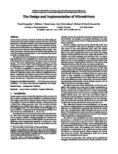
The observer pattern notifies observers when their subject’s state changes, so that they may update their own state to reflect this change. The state of a subject is modified via the SetState() operation, in which the subject invokes its own Notify() operation. The Notify() operation invokes the Update() operation of each observer to inform those observers of the subject’s state change. In an observer’s Update) operation, the notifying subject is asked to reveal its new state (via the GetState()) operation, which then becomes the new state of the observer. In summary, the observer pattern synchronises the state of observer objects with the evolving state of subjects with which they are registered. The dynamics of this synchronisation effort are depicted in figure A6.
Fig. A6. Observer Design Pattern: SetState() Pre Subject
Observer observers
observers
subject
Concrete Subjects
Concrete Observers
State
isa
isa
(State) () ()
subject
observerState () subjectState
( )
Post
State
observerState
subjectState
Precise Visual Specification of Design Patterns
133
References 1.
Abrial, J-R., Schuman, S., Meyer, B.: A Specification Language. On the Construction of Programs, McNaughten, R., and McKeag, R. (eds.), Cambridge University Press (1980)
2.
Booch, G.: Object-Oriented Analysis and Design With Applications (2nd Edition), Benjamin/Cummings (1993)
3.
Buschmann, F., Meunier, R., Rohnert, H., Sommerlad, P., Stal, M.: PatternOriented Software Architecture: A System of Patterns, Wiley (1996)
4.
Cook, S., and Daniels, J.: Designing Object Systems: Object-Oriented Modelling with Syntropy, Prentice-Hall (1994)
5.
Coplien, J., Schmidt, D. (eds.): Pattern Languages of Program Design, AddisonWesley (1995)
6.
D’Souza, D., and Wills, A.: Objects, Components and Frameworks with UML: The Catalysis Approach, Addison-Wesley (1998)
7.
Firesmith, D., Henderson-Sellers, B., Graham, I.: OPEN Modelling Language (OML) Reference Manual, SIGS Reference Library (1997)
8.
Fowler, M.: Analysis Patterns: Reusable Object Models, Addison-Wesley (1997)
9.
Gamma, E., Helm, R., Johnson, R., Vlissides, J.: Design Patterns: Elements of Reusable Object-Oriented Software, Addison-Wesley (1995)
10. Gil, J., and Kent, S.: Three Dimensional Software Modelling, Unpublished Manuscript (1998) 11. Jones, C.: Systematic Software Development using VDM (2nd edition), Prentice Hall (1990) 12. Kent, S.: Constraint Diagrams: Visualising Invariants in Object-Oriented Models, to appear in Procs. of OOPSLA97, ACM Press (1997) 13. Kent, S.: Visualising Action Contracts in Object-Oriented Modelling, submitted to Visual 98 (1998) 14. Pree, W.: Design Patterns for Object-Oriented Software Development, AddisonWesley (1995) 15. Reenskaug, T., Wold, P., Lehne, O. A.: Working With Objects, Manning Publications (1996)
134
Anthony Lauder and Stuart Kent
16. Rumbaugh, J., Blaha, M., Premerlani, W., Eddy, F., Lorensen, W.: ObjectOriented Modelling and Design, Prentice Hall (1991) 17. UML Consortium: The Unified Modelling Language Notation, version 1.1, http://www.rational.com (1997) 18. UML Consortium: The Unified Modelling Language Semantics, version 1.1, http://www.rational.com (1997) 19. UML Consortium: Object Constraint Language Specification, version 1.1, http://www.rational.com (1997) 20. Vlissides, J., Coplien, J., and Kerth, N., (eds.): Pattern Languages of Program Design 2, Addison-Wesley (1996)