Proceedings of the World Congress on Engineering 2007 Vol II WCE 2007, July 2 - 4, 2007, London, U.K.
Program for Structural Synthesis of the Multiple Fixtures N. Seghedin, C. Zlati, and N. Zlati
Abstract—This paper presents a program for structural synthesis -conception and design work-of the multiple fixture devices in the machine-tool structure. This program was created according to the principles of object-oriented programming. The program is also built upon two fundamental principles which characterize the evolution of the systems: the combination and the selection. The basic structural elements of the fixture devices are the clamping mechanisms. For this reason the program accomplishes clamping mechanism combinations, obtaining mathematically-possible combinations from which the combinations of technical incompatibility are excluded. Finally, the paper presents some fixtures functional structures obtained with the proposed program. Index Terms—computer-aided planning and design, clamping mechanisms, fixtures, object-oriented programming.
I. INTRODUCTION The multiple fixtures are subsystems of technological systems of chip removal machine work and they are destined for the fixture (locating and clamping) of more pieces during one technological operation. The computer-aided synthesis of fixtures represent an important preoccupation for engineers in the manufacturing systems field. Therefore, significant development was made in the field of computer-aided intelligent synthesis, and of fixtures out of modular elements [1]-[3]. Besides that, various automatic synthesis methodologies of the production system devices were structured [3]-[6]. Important advancements have been made concerning the genetic algorithms-aided synthesis of new fixtures [7]-[10]. Regarding clamping the pieces in devices, researches have been made concerning the determination of the optimum force of clamping [3], [9]. As far as the multiple clamping is concerned, researches have been made regarding the determination of the optimum force of clamping [10]. For structuring multiple fixtures, many researches have been made which primarily consisted in obtaining new structures of multiple clamping mechanisms in the construction of these devices [11], [12]. Furthermore, researches have been Manuscript received March 7, 2007. Neculai Seghedin. Eng. Ph.D., Associate Professor, Technical University “Gheorghe Asachi” Iaşi, Romania (phone: +40232271142; fax:
[email protected], +40232233924; (e-mail:
[email protected] ). Cătălin Zlati. M. Sc. in Computer Science, Platespin LTD, Toronto, Canada (e-mail:
[email protected]). Nicoleta Zlati. M. Sc. in Computer Science, Opalis INC, Toronto, Canada (e-mail:
[email protected]).
ISBN:978-988-98671-2-6
made concerning the possibilities of analysing the multiple clamping mechanisms, which is an essential condition for making an advanced synthesis of these mechanisms [13]. Analysing the literature of the field, one can notice that the multiple fixtures are characterised by important economical advantages. Thus, according to [14], these devices can lead to a time rate decrease of approximately 80 %. Therefore, when there are more pieces fixed in a device, the time rate decreases, among other reasons, because of: reducing the aiding time when fixing and detaching the pieces; reducing the basic time when using multiple tools; overlapping the basic time on the fixing-detaching aiding time, in the case of devices with charging-discharging stations. These economical advantages determine the multiple fixture study have a great importance in the engineering theory and practice. II. THE STRUCTURAL ANALYSIS OF THE MULTIPLE FIXTURES Since the purpose of this paper is the structural synthesis of multiple fixtures, it is necessary that first and foremost a structural analysis of the multiple fixtures is made. After analyzing a large number of multiple fixtures, the result showed that the multiple fixture integrants can be reunited in various groups, named structural categories. Therefore, the basic structural groups that build a fixture are: Locating Elements and Mechanisms; Clamping (Alignment-Clamping) Elements and Mechanisms; Action Elements and Mechanisms; Division Elements and Mechanisms etc [11]. From all the structural groups composing the multiple fixtures, it was noticed that the group with the most influence on the structural aspect of the device is the Clamping (Alignment-Clamping) Mechanism group. This is due to the fact that these mechanisms are, generally, the most complex and multiple in the structure of the fixtures. These mechanisms are the ones which transmit the necessary energy for clamping the pieces, from the (manual, hydraulic, pneumatic, electromagnetic, electric etc.) action sub-system of the fixture. III. THE STRUCTURAL ANALYSIS OF THE MULTIPLE CLAMPING MECHANISMS The structural analysis of the multiple clamping mechanisms is aimed to track down the component elements of these mechanisms and the manner in which these elements combine. The analysis of the multiple clamping mechanisms has been made on several levels. On a first analysis level, as a consequence of the study of a WCE 2007
Proceedings of the World Congress on Engineering 2007 Vol II WCE 2007, July 2 - 4, 2007, London, U.K.
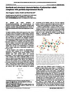
significant number of multiple clamping mechanisms, and according to the research papers [11]-[13], the result was that the general structure of multiple clamping mechanisms (for clamping the pieces P), contains three subsystems: the entry subsystem (In), the intermediary subsystem (Im) and the exit subsystem (Ie) (Fig. 1).
multiple); Ball (roller); Wedge (cone); Hydrorubber; Jointed bar; Rack-gear wheel; Screw–nut; Worm and gear; Gear wheel- gear wheel; Connecting rod; ─ Exit subsystem (Ie): Lever; Ram (jaw, prism); Spring; Lever-wedge; Wedge; Roller; Chuck. In
Clamping mechanism
Im
Ie
Ini
P1
Iek P2
Action system
Entry subsystem In
Intermediary subsystem Im
Exit subsyste m I
P
P1 Ini
ISBN:978-988-98671-2-6
Iek P2
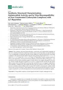
Fig. 1. The general structure of multiple clamping mechanisms The entry subsystem contains those elements through which the energy is transmitted from the action system at the other multiple clamping mechanism subsystems. There are also cases in which the clamping is made directly through the entry elements, because the other clamping mechanism are missing or the entry subsystem makes a contact with the pieces P1, P2, …Pn. The intermediary subsystem contains the elements which change (amplify or reduce) the action forces. The exit subsystem contains those elements which make close contact with the pieces–they are the elements which effectively assure the clamping of the pieces P into the fixture. On a second analysis level of the multiple clamping mechanisms, the structuring means (the functional structures) of the three (entry, intermediary, exit) subsystems were settled. Thus, the following conclusions resulted: ─ the entry subsystem is embodied by one single element, one of the multiple clamping mechanism characteristics being that the energy flux enters the mechanism through one single channel, after which there follows a dispersal of forces on more channels in order to simultaneously or gradually clamp more pieces; ─ the intermediary subsystem can be missing from the multiple clamping mechanism structure or it can be embodied in one, two, three or four clamping elements; ─ the exit subsystem can be missing, case in which it can be confused with the entry subsystem; this subsystem is embodied, almost always, by one single generic element, which is an element that can be found, at the same time, on more patterns of force transmission, patterns equal in number with the clamped pieces number. In Fig. 2, there are examples of functional structures of multiple clamping mechanisms. On a third analysis level of the multiple clamping mechanisms, clamping elements that are included in the entry, intermediary and exit subsystem structure were settled: ─ entry subsystem (In): Screw - nut (simple, left-right); Hydraulic (pneumatic) cylinder rod; Cam (eccentric) (simple, multiple); Lever; ─ Intermediary subsystem (Im): Ram (rod, pipe) (simple, special); Lever; Lever-hydrorubber; Cam (eccentric) (simple,
Imj
Imj
Iek
P1
Imj
Iek
P2
Imj
Iek
P3
Imj
Iek
P4
Imj Ini Imj
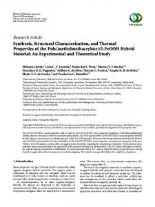
Fig. 2. Examples of functional structures of multiple clamping mechanisms (i=1... 4; j=1... 13; k=1... 7) IV. THE STRUCTURAL SYNTHESIS PROGRAM OF THE MULTIPLE FIXTURES The GENERATOR program, created in Visual C++ allows the obtaining of new functional structures of multiple clamping mechanisms, by the logical combination of the clamping elements in the entry, intermediary and exist subsystems. The program excludes the technically incompatible combinations and organizes the technically compatible combinations according to the extent to which these combinations meet certain appreciation criteria. The GENERATOR program uses the elements of the C++ programming language for a class and object programming. The object-oriented programming (object-oriented techniques) is based on the concepts of class, object and a set of paradigms – the abstraction of the data and communication through messages, encapsulating, inheritance, polymorphism and dynamic binding. In the object-oriented software engineering, the object-oriented analysis and the object-oriented design work-synthesis are very important. All remarcable methodologies of object-oriented software development impose, in the analysis stage, the identification and itemizing (attributes, behaviour, relationships) of the abstractions in the application field. The premise of an object-oriented computational model is that the data nature of any application consists in a collection of objects as referrals to some classes. The architecture of the object systems is based on classes, objects, and the interactions between them. In the case of multiple clamping mechanisms, the classes are represented by the three subsystems: the entry, intermediary and exit subsystems. The objects – the clamping elements –
WCE 2007
Proceedings of the World Congress on Engineering 2007 Vol II WCE 2007, July 2 - 4, 2007, London, U.K.
Code
Constructive variants simple E
Screwnut
In1a
T
left-right
In1
E1 I R
In1b
T E2
Fig. 3. The screw-nut entry element as an object According to object-oriented programming theory, every object must be described by a value. These values given to the objects (clamping elements) will be the base of the evaluation and regulation (arrangement) of the combinations that will be made by the GENERATOR program. We opted for the determination, for each clamping element, of some value numbers obtained by implementing the imposed decision technique, from the value engineering. These value numbers are obtained according to the extent to which every clamping element meets certain appreciation criteria. For the clamping elements which are entry elements the systematisation criteria are: operating mechanization possibility (OM); capacity of the forces distribution (FD); cost (C); selfbreaking characteristics (SB); capacity of the forces amplification (FA); efficiency (EF). The clasification criteria for the clamping elements from the intermediary subsystem are: capacity of the forces distribution (FD); cost (C); selfbreaking characteristics (SB); capacity of the uniform application of the forces (U); efficiency (EF); capacity of the forces amplification (FA). The clasification criteria for the exit clamping elements are: size of the contact tension between the clamping element and the piece (CT); efficiency (EF); capacity of the uniform application of the forces (U); capacity of the clamping of the different configuration pieces (DC); selfbreaking
ISBN:978-988-98671-2-6
DECISIONS D 1 2
I R
Table I. Weighing the appreciation criteria for the entry elements
3
4 5 6 7
8 9 10 11 12 13 14
OM 1 1 0.5 1 1 1 0.5 0.5 1 FD 0 0 0 0 0.5 0 C 05 05 1 0.5 0.5 SB 0 0.5 05 0.5 FA 0 0 1 0.5 EF
15
1 0
Total decisions D
Name of object
characteristics (SB); capacity of the forces amplification (FA); cost (C). We used the “imposed decision” technique from the value engineering for the global evaluation of the clamping elements. So, each clamping element will be characterized by a value (valuable) number (NV) according to the way the appreciation criteria are solved. First, a balanced sample of the appreciation criteria must be made. The criteria are compared one to the other and this is how the D decisions are obtained: 1-0; 0,5-0,5; 0-1. For example, in Table I the weighing of the appreciation criteria for the entry elements is presented.
Appreciation criteria for the entry elements
consist in the component elements of the three subsystems. The interactions refer to the clamping elements combining manner etc. The referral objects of some classes have an inner structure and an outer behaviour defined by the class which they belong to. Therefore, the clamping elements are characterised by a certain number of entries and exits, as an expression of their inner structure. The outer behaviour is characterised by the value number which expresses the extent to which various criteria have been met. The same element can have various value numbers, according to the class (subsystem) which it belongs to. Essentially, an object has a state, a behaviour and an identity. As a first phase, to characterise these objects, with regard to the computer-aided synthesis, the following data must be pointed out: name, code, types of movement during the entry and the exit (rotation = R, translation = T), number of entries (I), number of exits (E). An example of a clamping element considered an object is presented in image three.
Weighting factor WN (WN=D/15)
4.5 3 0.5 3 2.5 1.5
WNOM=0.30 WNFD=0.20 WNC=0.03 WNSB=0.20 WNFA=0.16 WNEF=0.10
Using this method, the appreciation criteria are re-arranging as in the following model: a. The entry elements appreciation criteria (weights WN): 1-Operating mechanization possibility (OM) (WNOM = 0.3); 2-Selfbreaking characteristics (SB) (WNSB = 0.2); 3-Capacity of the forces distribution (FD) (WNFD = 0.2); 4-Capacity of the forces amplification (FA) (WNFA = 0.16666); 5-Efficiency (EF) (WNEF = 0.1); 6-Cost (C) (WNC = 0.03333). b. The intermediary elements appreciation criteria (weigts WM): 1-Capacity of the uniform application of the forces (U) (WMU = 0.26666); 2-Capacity of the forces distribution (FD) (WMFD = 0.23333); 3-Capacity of the forces amplification (FA) (WMFA = 0.2); 4-Selfbreaking characteristics (SB) (WMSB = 0.13333); 5-Efficiency (EF) (WMEF = 0.13333); 6-Cost (C) – (WMC = 0.03333). c. The exit elements appreciation criteria (weights WE): 1-Size of the contact tension between the clamping element and the piece (CT) (WECT = 0.26190); 2-Capacity of the uniform application of the forces (U) (WEU = 0.23809); 3-Capacity of the clamping of the different configurations pieces (DC) (WEDC = 0.16666); 4-Capacity of the forces amplification (FA) (WEFA = 0.16666); 5-Efficiency (EF) (WEEF = 0.07142); 6-Selfbreaking characteristics (SB) (WESB = 0.04761); 7-Cost (C) – (WEC = 0,04761). Next, the value numbers for each clamping element must be fixed. The value numbers for each element are obtained using the comparison, by all appreciation criteria, of the elements (which are components of each subsystem). For example, in Table II the comparison of the entry elements after the OM criteria, for obtaining the total decisions (DOM)is presented. The same way, the decisions DSB, DFD, DFA are obtained etc.
WCE 2007
Proceedings of the World Congress on Engineering 2007 Vol II WCE 2007, July 2 - 4, 2007, London, U.K.
Table II. Comparison of the entry elements after the OM criteria (i = 1…4) Entry elements In
DECISIONS D 1
2
3
Screw-nut 0 Hydraulic 1 cilinder rod Cam (eccentric) Lever
05
0
4
1 05
5
0.5
0 1
6
0.5
0 1
Total decisions DOMi
DOMi/6
0.5
0.83333
2.5
0.41666
0.5 2.5
0.08333 0.41666
The value numbers (NV) for these elements are established in order to the decisions (D) made after the comparison, one to another, of these elements using each of the criteria, the number of the decisions and the criteria weight. Thus, the general formula for the value numbers calculation for the entry elements (Ini, i=1…4) is: D D D NV (Ini ) = OMi ⋅ WN OM + SBi ⋅ WN SB + FDi ⋅ WN FD + 6 6 6 DFAi DEFi DCi ⋅ WN FA + ⋅ WN EF + ⋅ WN C . 6 6 6 The same way, each intermediary element (Imj, j=1 13) will receive a value number, after the formula : DUj DFDj DFAj NV Im j = ⋅ WM U + ⋅ WM FD + ⋅ WM FA + 78 78 78 DSBj DEFj DCj ⋅ WM SB + ⋅ WM EF + ⋅ WM C . 78 78 78 In a similar manner, the value numbers for the exit elements (Iek, k=1...7) are established using the formula: D D D NV (IeK ) = CTk ⋅ WECT + Uk ⋅ WEU + DCk ⋅ WE DC + 21 21 21 DFAk DEFk DSBk D ⋅ WE FA + ⋅ WE EF + ⋅ WE SB + Ck ⋅ WEC . 21 21 21 21 In Table III, the value numbers of the clamping elements belonging to the three subsystems are determined. The relations between objects, between classes, and between classes and objects represent, in fact, the essence of the computer based synthesis program of the multiple clamping mechanisms. In other languages, these relations are called rules and they underlie the structuring of the inference motors that characterize artificial intelligence. The relations have been stated, formulated and structured after many observations and analysis on multiple clamping mechanisms. So, one of the first structuring rules is that multiple clamping mechanisms may have a liniar structure, as well as an arborescent, branched structure, and because of this, for each clamping element, the number of the convection tracks, for the input and output must be specified. A very important rule or relation between objects is the on concerning the layout order of the clamping elements inside a combination. This rule is stated as the principle of the movement transmition compatibility: the imperative condition for a two-clamping element sequence to be technically viable is that the first element’s output must coincide, concerning the movement form, with the second element’s input.
( )
ISBN:978-988-98671-2-6
Table III. The value numbers of the clamping elements belonging to the three subsystems. Code In1 In2 In3 In4 Code Im1 Im2 Im3 Im4 Im5 Im6 Im7 Im8 Im9 Im10 Im11 Im12 Im13 Code Ie1 Ie2 Ie3 Ie4 Ie5 Ie6 Ie7
Entry subsystem Clamping Elements Hydraulic (pneumatic) cylinder rod Screw - nut (simple, left-right) Lever Cam (eccentric) (simple, multiple) Intermediary subsystem Clamping Elements Hydro-rubber Lever-hydro-rubber Lever Ball (roller) Wedge (cone) Cam (eccentric) (simple, multiple) Screw - nut (simple, left-right) Worm and gear Rack-gear wheel Gear wheel- gear wheel Jointed bar Connecting rod Ram (rod, pipe) (simple, special) Exit subsystem Clamping Elements Lever Chuck Ram (jaw, prism) Spring Ball(roller) Lever-wedge Wedge
Nv 0.32499 0.26666 0.25277 0.19721 Nv 0.10208 0.10033 0.09285 0.09285 0.08315 0.08174 0.07824 0.07042 0.06576 0.06149 0.05995 0.05837 0.04999 Nv
0.16835 0.15338 0.15146 0.14182 0.13093 0.12923 0.12470
Computer instructions are structured in such a way that, if this condition is not achieved inside a combination, then the whole combination is deleted. This is the reason why the movement form of the input and output has been defined (rotation R and translation T) for each element inside the three subsystem structures (entry, intermediary and exit). In Fig.3 the use of the principle of the movement transmition compatibility is presented in a simplified way.
YES
NO
R In2 T
R Im6 T
T
Ie1
T
NO
Fig. 3. The use of the principle of the movement transmition compatibility The program allows structuring a data base that contains the elements inside the three subsystems. Inside this data base (Fig.
WCE 2007
Proceedings of the World Congress on Engineering 2007 Vol II WCE 2007, July 2 - 4, 2007, London, U.K.
4), the name, the belonging subsystem, the motion form which characterizes the entries and the exits, the minimum and the maximum number of entries and exit, and the value number for each element are specified.
solutions concerning these kinds of mechanisms.
Fig. 4. The data base with clamping elements In Fig. 5 the main window of the program is presented.
Fig. 6. Choosing the entry subsystem elements.
Fig. 5. The main window of the program. Fig7. Choosing the intermediary subsystem elements. To generate various functional structures of multiple clamping mechanisms, the elements that will embody the entry subsystem, the intermediary subsystem and the exit subsystem must be selected (Fig. 6, Fig. 7 and Fig. 8). The program allows the visualization of the elements chosen for combination (Fig. 9). Another thing to be determined is how many levels (one, two or three) the contact elements must be set on, and then the combination, selection and arrangement process starts. The program arranges the obtained combination, according to the sums of the elements’ value numbers. In Fig. 10 the arrangement of the obtained combinations is presented. The program allows the visualization of the obtained combinations. These combinations can symbolize functional structures of some existent solutions concerning the multiple clamping mechanisms, or belonging to some new, unknown
ISBN:978-988-98671-2-6
In this latter case, the obtained combinations can underlie in making some creation themes in the multiple fixtures field. In Fig. 11 some functional systems obtained with the GENERATOR program are presented. V. CONCLUSIONS The GENERATOR program can be used as a means of obtaining new creation themes in the field of multiple fixtures, being at the same time, an efficient tool in stimulating technical creativity. The program can be improved by associating it with data bases containing graphical representations of clamping elements that combine in such a way that in the end structures of multiple clamping elements at the level of technical solution result, not only at the level of functional structure. Moreover, it
WCE 2007
Proceedings of the World Congress on Engineering 2007 Vol II WCE 2007, July 2 - 4, 2007, London, U.K.
may forecast subprograms that can allow an automatic dimensioning of the obtained technical solutions.
Fig. 11. Functional systems obtained with the GENERATOR program REFERENCES Fig. 8. Choosing the exit subsystem elements.
[1] [2] [3] [4] [5] [6]
[7] [8]
Fig. 9. The visualization of the elements chosen for combination
[9] [10] [11] [12]
[13]
[14]
A. Senthil Kumar, J. Y. H. Fuh and T. S. Kow, “An automated design and assembly of interference-free modular fixture setup”, Computer-Aided Design, Vol. 32, Issue 10, 1 Sept. 2000, pp. 583-596. Y. Wu, Y. Rong, W. Ma and S. R. LeClair, “Automated modular fixture planning: Geometric analysis”. Robotics and Computer-Integrated Manuf., Vol. 14, Issue 1, February 1998, pp. 1-15. A.Y.Nee, Z.J.Tao, A. and Sentil Kumar, An Advanced Treatise on Fixture Design and Planning. World Scientific Publishing, Singapore, 2004. Y. Wang , X. Chen, Q. Liu and N. Gindy, “Optimisation of machining fixture layout under multi-constraints”, Int. Journal of Machine Tools and Manuf., Vol. 46, Issues 12-13, Oct. 2006, pp. 1291-1300. R. Hunter, J. Rios, J.M. Perez and A. Vizan, “A functional approach for the formalization of the fixture design process”, Int. Journal of Machine Tools and Manuf., Vol. 46, Issue 6, May 2006, pp. 683-697. Bijan Shirinzadeh, “A CAD-Based hierarchical approach to interference detection among fixture, modules in a reconfigurable fixturing system”, Robotics and Computer-Integrated Manuf., Vol. 12, Issue 1, March 1996, pp. 41-53. Necmettin Kaya, “Machining fixture locating and clamping position optimization using genetic algorithms”, Computers in Industry. Vol. 57, Issue 2 , February 2006, pp. 112-120. K. Kulankara, S. Satyanarayana and S.N. Melkote, “Iterative fixture layout and clamping force optimization using the genetic algorithm”, J. of Manuf. Sc. and Eng.-Trans. of the ASME, 124 (1), Feb. 2002, pp. 119-125. Z.J. Tao, A.S. Kumar, A.Y.C. Nee, “A computational geometry approach to optimum clamping synthesis of machining fixtures”, Int. Journal of Production Research, 37 (15), Oct. 15, 1999, pp. 3495-3517. B. Li, S.N. Melkote, “Fixture clamping force optimisation and its impact on workpiece location accuracy”, Int. Journal of Adv. Manuf. Technology, 17 (2), 2001, pp. 104-113. N. Gherghel, Resurse metodologice de creativitate în domeniul dispozitivelor de prindere. Revista de inventica, vol. III, anul VI, nr. 15, 1995, pp. 6 ─ 9. N. Seghedin, N. Gherghel, C. Zlati, N. Zlati, “Computer-Aided Structural Synthesis of the Multiple Clamping Mechanisms”, Proceedings of the 9th International DAAAM Symposium“, Published by DAAAM International, Cluj-Napoca, 22-24 october, 1998, pp. 431-432. N. Seghedin, “Rules on the fixtures synthesis using the object-oriented programming”. Proceedings of the 10th International DAAAM Symposium, Published by DAAAM International, Vienna, Austria, 21- 23 october 1999, p. 491-492. H. Matuszewski, Handbuch Vorrichtungen. Konstruktion und Einsatz, Vieweg Verlag, Braunschweig, 1986.
Fig. 10. The arrangement of the obtained combinations. ISBN:978-988-98671-2-6
WCE 2007