ARTICLES PUBLISHED ONLINE: 10 JULY 2011 | DOI: 10.1038/NCHEM.1070
Programmable molecular recognition based on the geometry of DNA nanostructures Sungwook Woo1 * and Paul W. K. Rothemund1,2,3 * From ligand–receptor binding to DNA hybridization, molecular recognition plays a central role in biology. Over the past several decades, chemists have successfully reproduced the exquisite specificity of biomolecular interactions. However, engineering multiple specific interactions in synthetic systems remains difficult. DNA retains its position as the best medium with which to create orthogonal, isoenergetic interactions, based on the complementarity of Watson–Crick binding. Here we show that DNA can be used to create diverse bonds using an entirely different principle: the geometric arrangement of blunt-end stacking interactions. We show that both binary codes and shape complementarity can serve as a basis for such stacking bonds, and explore their specificity, thermodynamics and binding rules. Orthogonal stacking bonds were used to connect five distinct DNA origami. This work, which demonstrates how a single attractive interaction can be developed to create diverse bonds, may guide strategies for molecular recognition in systems beyond DNA nanostructures.
D
NA base pairing is unique among mechanisms for molecular recognition1 because it allows the creation of combinatorially diverse bonds: the number of possible binding interactions scales exponentially with polymer length so that a polymer of just N nucleotides A, T, G or C can express on the order of 4N binding interactions. In practice, many sequences are unusable because they exhibit undesired interactions with themselves or other sequences. However, with attention to base composition, secondary structure, sequence homology and thermodynamics, extremely large sets of orthogonal sequences (!240,000, N ¼ 25) can be designed to bind within a narrow range of melting temperatures2. This ability to instantiate diverse binding interactions has driven the creation of a wide variety of DNA nanostructures3–8, molecular computers9–11 and nanomachines12–14. Although DNA hybridization is extremely powerful, researchers have developed numerous artificial systems for molecular and macroscopic recognition using simple interactions, including hydrogen bonds15, p–p stacking16,17, entropic depletion18,19 and capillary forces20,21. There has been little development, however, of general systems capable of creating combinatorially diverse bonds; each new type of interaction typically requires unique design insights and considerable synthetic effort. Besides DNA, other information-bearing heteropolymers, such as proteins, might be used for combinatorially diverse bonds. However, even for wellunderstood systems (for example, protein coiled coils22) no systematic method exists for designing multiple orthogonal bonds. Towards understanding and recreating the recognition properties of DNA it is natural to ask, ‘What causes two complementary DNA strands to bind?’ Although the first answer that may spring to mind is the hydrogen bonding between base pairs, base stacking between adjacent base pairs is apparently the dominant stabilizing factor in DNA binding23–25. The dominance of stacking is consistent with the sequence-dependent strength of DNA binding because stacking is itself sequence-dependent: the strongest stacking occurs between a GC pair and a CG pair (–2.17 kcal mol21), and the weakest stacking is at AT/TA (–0.19 kcal mol21) (ref. 24).
The nearest-neighbour model for the strength of DNA binding26–28 owes its success over the base-composition model (simply counting AT and GC pairs) to the fact that it includes stacking. One consistent picture is this: stacking provides much of the binding enthalpy for the duplex, and base pairing enforces specificity. The question arises whether stacking alone can be used to create specific molecular recognition. Pure base stacking can be studied by examining the binding between blunt ends, the termini of a DNA duplex. Blunt-end stacking between individual duplexes is directly observed only at extremely high (!100 mM) concentrations29, but DNA nanostructures, such as three-helix tiles30 and 24-helix origami5, form long chains at much lower (500 nM and 1 nM, respectively) concentrations because of the cooperative binding of multiple blunt ends. In achieving specific bonds using stacking, some difficulties might be expected. First, in contrast to base pairing, which involves heterophilic (‘like–unlike’) attraction, blunt-end stacking involves homophilic (‘like–like’) attraction. Whether combinatorially diverse bonds in homophilic polymers are even possible has been an open question since Crick first suggested that the primitive genetic code might have been homophilic31. Second, DNA uses two types of attraction (A-T and G-C), so how can combinatorially diverse bonds be constructed from just a single type of attraction? Here we present two general approaches to programming combinatorially diverse and specific bonds in a scalable fashion from a single homophilic interaction. Both approaches use DNA origami to create stacking bonds: geometric arrangements of stacked blunt ends. We mapped these arrangements onto abstract sequences, used computer algorithms to find sets of sequences predicted to be orthogonal and experimentally tested sets for orthogonality. The first approach encodes bond type using a 16-bit binary code along the edges of an origami rectangle. It is reprogrammable and efficient: a single set of 16 strands can create 216 ¼ 65,536 bond types. The second approach encodes bond type using geometric complementarity between pairs of ‘Manhattan skyline’ edge shapes, with N ‘skyscrapers’ each having one of M heights; the
1
Department of Bioengineering, California Institute of Technology, Pasadena, California 91125, USA, 2 Department of Computer Science, California Institute of Technology, Pasadena, California 91125, USA, 3 Department of Computation & Neural Systems, California Institute of Technology, Pasadena, California 91125, USA. * e-mail:
[email protected];
[email protected]
NATURE CHEMISTRY | ADVANCE ONLINE PUBLICATION | www.nature.com/naturechemistry
© 2011 Macmillan Publishers Limited. All rights reserved.
1
ARTICLES
NATURE CHEMISTRY
a
c
b 10.67 bp/turn
DOI: 10.1038/NCHEM.1070
10.44 bp/turn
+
Dumbbell hairpin
d
Base deletion columns
Single-stranded loopouts
e
f 15 nt h2t
v-flip
h-flip
h2t
16 nt
g h2t
rot
h2t
rot
rot
rot
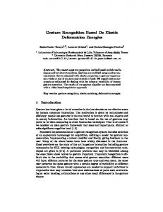
Figure 1 | Stacking of rectangles. a, A long scaffold strand (black) is folded by multiple short staple strands to form a rectangle; features include edge staples (blue and red), interior staples (grey), dumbbell hairpins (orange ovals) and single-stranded loopouts (black bulges). The grey box indicates an area enlarged in (f). Each column of staples was originally 16 nucleotides (nt) wide5; in twist-corrected rectangles, columns with base deletions (pink) are 15 nt wide. b,c, AFM comparison of rectangle chains without (b) and with (c) twist correction, deposited on mica. Upper left insets show models of single rectangles. Lower right inset (b) models how periodic breaks arise in a twisted chain during deposition. d, Proposed structure of a ‘stressed edge’. e, Model and AFM image of rectangles with ‘stressed edges’. Solid vertical bars indicate that no stacking polarity is expected. Dashed vertical arrows emphasize that edges do not bond in an exclusively antiparallel orientation, as exemplified by rectangles related by 1808 horizontal or vertical flips (indicated by half-circle arrows with an in-plane axis of rotation). Rectangles bind in head-to-tail (h2t), rotated (rot), horizontally flipped (h-flip) and vertically flipped (v-flip) orientations. f, Proposed structure of a ‘relaxed edge’. g, Model and AFM images of rectangles with ‘relaxed edges’ (a larger example shown in c). Vertical arrows label stacking polarity; only ‘antiparallel’ bonds form. Half-circle arrows indicate 1808 rotation (about an axis going into the plane through the centre of a bond). Scale bars: 500 nm (b,c); 100 nm (e,g).
case of N ¼ 4 and M ¼ 3 with 34 ¼ 81 bond types was explored. This approach is not reprogrammable (each origami is ‘hard-coded’; a unique origami must be synthesized for each shape), but it is experimentally simpler. In both systems, symmetry and mismatch constraints limit the number of bond types and size of orthogonal sets. Non-idealities, such as the flexibility of edges, further decrease the number of usable bond types. We demonstrate the combination of origami using orthogonal sets of up to four distinct bond types. Finally, we use both systems to control the cis/trans geometry of multi-origami structures.
Results and discussion Stacking of origami rectangles. We first explored stacking using a rectangular origami with 24 blunt ends along each edge (Fig. 1a). Approximately 200 staple strands (typically 32 nucleotides) were used to fold a scaffold strand (!7,000 nucleotides) into the desired shape. An L-shaped pattern of dumbbell hairpins5 was added to provide height contrast under atomic force microscopy (AFM). Crossovers are positions at which a strand jumps from one helix to another. Previously, we observed stacking of similar 24-helix rectangles into long chains (up to 5 mm) (ref. 5). However, the quality of the chains was low: they exhibited complete breaks (as in Fig. 1b) or dislocated bonds (with edges in partial contact, as in Fig. 1e) and the bonds between origami occurred in all four possible orientations (as in Fig. 1e). We hypothesized that three factors might be responsible: (1) the sequence of blunt-end base pairs was random, (2) the origami had a large global twist and (3) the blunt ends had a crossover geometry incompatible with B-form stacking. We reduced or eliminated all three factors, demonstrated that at least (2) and (3) contributed to the low quality of chains, and obtained straight linear chains with only two orientations. 2
Regarding (1), the sequence at blunt ends: in principle, the strength of stacking bonds with random blunt-end sequences could vary by a factor of !11 (22.17/20.19) for all ‘GC’ versus all ‘AT’ pairs. Thus, in all the experiments presented here, we decreased potential variability by placing a ‘GC’ base pair at each blunt end. This was achieved by introducing single-stranded loopouts in the scaffold (Fig. 1a) to shift the scaffold sequence until a ‘GC’ occurred at the adjacent pair of blunt ends (Supplementary Note S2.4). Regarding (2), the global twist: B-form DNA has a helical twist of 10.4 base pairs/turn (bp/turn) (ref. 32). The original rectangles5 were designed using a helical twist of 10.67 bp/turn, which was found to induce a significant global twist (recently studied in detail33,34). Here, we achieved an average helical twist of 10.44 bp/turn by deleting one base from every third column of staples (Fig. 1a) using our design code or caDNAno (ref. 35). Two AFM images show the difference in quality between chains formed by rectangles without (Fig. 1b) and with (Fig. 1c) twist correction when deposited on mica. Whereas chains of twisted origami break with a characteristic offset (with a chirality consistent with a right-handed superhelix) every 2–6 origami, chains of twistcorrected origami exhibit rare breaks. For twisted and twist-corrected origami, factors (1) and (3) were minimized by design. Regarding (3), the crossover geometry at blunt ends: in general, we expect deviations from the B-form to weaken stacking23. The original rectangles were designed with a set of edge staples that resulted in a crossover at every available location between adjacent blunt ends (Fig. 1d). In such edges, a conflict may arise because (i) the simultaneous presence of the scaffold and staple crossovers pulls the phosphates of scaffold and staples towards positions 1808 away from each other and (ii) the major–minor groove relationship of a B-form base pair naturally places the phosphates
NATURE CHEMISTRY | ADVANCE ONLINE PUBLICATION | www.nature.com/naturechemistry
© 2011 Macmillan Publishers Limited. All rights reserved.
ARTICLES
DOI: 10.1038/NCHEM.1070
a
b
‘1’
Inactive patch
‘0’
1011010100010001
Active patch
‘1’
1011010100010001
NATURE CHEMISTRY
0001011110001100
110000
0010
1100
1100
1110
001011
001101
111000
001001
011100
001001
000101
0 00 1 0 1 1 1 1 0 0 0 1 1 0 0
c
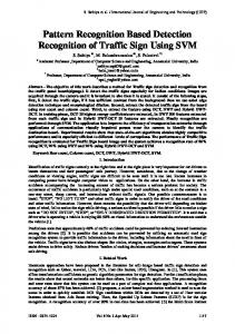
Figure 2 | Recognition based on binary sequences of blunt ends and scaffold loops. a, Model and AFM images of a 32-helix tall rectangle that enables 16-bit binary codes. Addition of a staple at a specific edge site creates two blunt ends, which compose an active patch (‘1’); omission of the staple leaves a single-stranded loop that forms an inactive patch (‘0’). Use of an asymmetric sequence ‘0001011110001100’ with seven active patches creates long chains with an exclusively head-to-tail orientation. Active patches can be clearly observed; each doublet of helices typically appears as a single grey bar across the bond. Scaffold loops have a more variable appearance (sometimes invisible, sometimes appearing almost as prominently as an active patch), presumably because of variable conformation or, potentially, some loop–loop binding. b, A bent-patch bond, a common error for binary-coded bonds. Here, helix bending allows a five-patch bond that would otherwise not occur. c, AFM image of a five-rectangle chain built using four orthogonal bond types. Inset shows dumbbell hairpin labels. Scale bars: 60 nm.
1508 apart. Thus, such ‘stressed edges’ seem incompatible with any geometry in which all of the blunt ends are in native form, and they might be expected to weaken or otherwise change stacking. Many different non-B-form geometries could resolve the stress at such edges, including breakage of the final base pair or a change in major/minor groove angles; accurately predicting what happens lies beyond the state of the art. We propose that near flattening of the major and minor grooves decreases the distinction between them (Fig. 1d) and creates a top– bottom pseudosymmetry that prevents stacking from exhibiting a strongly preferred orientation. Experimentally, just such a promiscuity of orientation is observed: rectangles bind in head-to-tail (34% of total bonds), rotated (44%), horizontally flipped (17%) and vertically flipped (5%) orientations (N ¼ 174, Fig. 1e). Further, dislocated bonds are often observed (71%). One interpretation is that the bonds are well-aligned in solution, but dislocate on deposition. Another is that the dislocated bonds form in solution as kinetically trapped states; the stressed blunt ends might take on a corrugated geometry that, once bound, cannot easily slide to find a more stable state. Edge staples were redesigned so that there were no staple crossovers (Fig. 1f). In such ‘relaxed edges’, blunt ends are free to assume normal B-form groove angles. Rectangles with ‘relaxed edges’ can bind via near-B-form stacking (Supplementary Note S2.5) in head-to-tail and rotated orientations, but not in flipped orientations because of their strong top–bottom asymmetry. The results of our experiments are consistent with the hypothesis that near-B-form stacking is preferred; only head-to-tail (42% of total bonds) and rotated orientations (58%) were observed (N ¼ 318, Fig. 1g). Further, dislocations are exceedingly rare (1%). This is consistent with the idea that either (i) stacking bonds based on ‘relaxed edges’ are stronger than those formed from ‘stressed edges’ or (ii) ‘relaxed edges’ are more geometrically uniform (thus allowing any dislocated bonds that form as kinetic
products to slide and become full bonds). Origami in Fig. 1e,g have factors (1) and (2) minimized by design. The asymmetry of ‘relaxed edges’ gives stacking bonds a pleasant property analogous to the antiparallel nature of DNA hybridization: if we label ‘relaxed edges’ with arrows according to their asymmetry, we see that two edges form a bond only if the arrows point in opposite directions. Thus, the arrows define an antiparallel stacking polarity. We label edges such that when the major grooves at an edge point up, the arrow’s direction matches the 5′ to 3′ polarity of the scaffold at the edge. Stacking polarity allows stacking bonds to specify unique products by breaking the symmetry of otherwise symmetric bonds. Recognition based on binary codes. Stacking between two origami edges can be largely abolished by omitting their edge staples5: each omitted staple prevents the formation of two blunt ends and leaves a 32-nucleotide single-stranded scaffold loop. Sufficient complementarity between such loops could allow them to associate. For the M13mp18-based designs used so far, origami without edge staples do not aggregate, which suggests that scaffold loops may act primarily as entropic brushes with no affinity36. The key idea, then, is to encode specificity using stacking sequences: binary sequences of blunt ends and scaffold loops (abbreviated to ‘sequences’ when clear). A stacking bond based on such sequences should have maximum strength when the sequences are aligned to maximize the number of blunt-end interactions (assuming the change in Gibbs free energy, DG, is zero for potential loop–loop and loop–blunt end interactions; we revisit these assumptions later). We implement binary sequences by dividing edges into patches. Each patch is a two-helix wide section of edge; it contains a single scaffold loop to represent ‘0’ or a doublet of blunt ends to represent ‘1’ (Fig. 2a). There is a 1–1 correspondence between each edge staple and a particular patch. Including an edge staple in the reaction mixture yields an active patch (‘1’) capable of
NATURE CHEMISTRY | ADVANCE ONLINE PUBLICATION | www.nature.com/naturechemistry
© 2011 Macmillan Publishers Limited. All rights reserved.
3
ARTICLES
NATURE CHEMISTRY
stacking; omitting the same staple yields an inactive patch (‘0’). We explored 16-bit codes using a 32-helix tall rectangle. Given the number of bits available, our goal was to construct a code for the largest set of specific bond types possible and to use this set to connect the longest chain of distinct rectangles possible. To construct such a code, it is crucial to understand the binding rules of binary-coded stacking bonds. Stacking sequences are read in the direction of the stacking polarity. Just as the 5′ to 3′ polarity of DNA ensures that a DNA sequence is not, in general, equal to its reverse (‘ATGC’ = ‘CGTA’), stacking polarity ensures that a stacking sequence is not, in general, equal to its reverse (‘1011’ = ‘1101’). However, whereas the complementary sequence to a DNA sequence is its reverse complement (‘ATGC’ binds to ‘GCAT’), the complementary sequence to a stacking sequence is simply its reverse (‘1011’ binds to ‘1101’). Another parallel distinction is that, whereas a self-complementary DNA sequence must be a reverse palindrome (‘AGCT’ binds itself ), a self-complementary stacking sequence must be a palindrome (‘0110’ binds itself). The latter two differences result from the homophilicity of blunt-end stacking, but they highlight the importance of stacking polarity as a symmetry breaker; without stacking polarity, non-palindromic stacking sequences would also be self-complementary, because an origami bearing any sequence could bind itself in a horizontally flipped orientation. Palindromic sequences are useful when a two-fold rotational symmetry is desired (as in Fig. 4c). If a non-palindromic sequence, stripped of leading and lagging zeros, is still non-palindromic (e.g. ‘0010110’ # ‘1011’), it specifies a stacking bond with a unique head-to-tail orientation (Fig. 2a) and we say such a sequence is uniquely orienting. Like DNA sequences, stacking sequences can be partially complementary; thus, origami can make partial bonds with a strength equal to the number of matching active patches. When origami with fully complementary stacking sequences match at every patch, they make a full bond. Partial bonds and other undesired bonds are incorrect; full bonds are correct. A set of stacking sequences is considered orthogonal under mathematically defined mismatch constraints similar to those used for DNA sequences. In practice, experimental claims of orthogonality must be accompanied by correct bond yields. DNA strands of the same base composition (percentage of A, C, G and T) have similar bond energies; we say that stacking sequences with the same number of ‘1’s have the same weight and assume that the corresponding stacking bonds will have similar bond energies; that is, they are roughly isoenergetic (we provide evidence later). We began our search for a code with the largest set of orthogonal sequences by first narrowing the search to non-orthogonal candidate sets of sequences that were of constant weight and uniquely orienting, and that minimized undesired self-interactions. Candidate sets were parameterized by the number of active patches p in a correct bond and by the mismatch constraint i, the maximum strength of all possible partial bonds (considering all possible alignments between a sequence and itself as well as those between a sequence and its complement). Computer search was used to exhaustively determine candidate sets for values of p ¼ 5 to 10 and i ¼ 2 to 6, with i , p; for example, ( p, i) ¼ (7, 4) contained 4,614 sequences. Using the same mismatch constraint for interactions between sequences, we found the largest orthogonal subsets we could by greedy search (Supplementary Note S2.3). From these we chose a code by considering both theoretical and experimental estimates of error rates. For a sequence of given ( p, i) the energy difference between its correct and strongest partial bonds is 2DGst ( p – i), where DGst is the energy of a blunt-end stack. Thus, the lowest error rate might be expected for codes that maximize p – i (assuming a similar degeneracy of strongest partial bonds across different codes). The maximum p – i for which we found reasonably sized codes (with at least ten orthogonal sequences) was 3; (7, 4), 4
DOI: 10.1038/NCHEM.1070
(8, 5) and (9, 6) fit this criterion. We concentrated on (7, 4) codes because preliminary experiments suggested that these would give the lowest error rates (Supplementary Note S2.1.3). We investigated two of the largest (7, 4) codes we found, one with 11 orthogonal sequences and the other with 12. Correct bond/total bond fractions for their 23 individual sequences ranged from 73% to 98% (average, 87%). Figure 2a shows one of the better sequences (94.4%, N ¼ 659). Although predicted four-active-patch incorrect bonds were observed, a significant source of error came from bonds not considered in the design process: the flexibility of active patches allows them to form bent-patch bonds that encompass five or more active patches (Fig. 2b). We observed that contiguous runs of active patches were less likely to form bent-patch bonds than isolated active patches or pairs of active patches. Thus, we verified the orthogonality of multiple sequences using a subset of the 11sequence code for which the sequences all had runs of at least three active patches in a row (‘111’). Figure 2c shows the four sequences that were used, and a five-origami chain made with this code; all-‘0’ null bonds were applied to the left edge of the first origami and the right edge of the fifth. 88% of total bonds (N ¼ 66) observed were correct bonds, a rate similar to that observed for single bond types in isolation. Further, the rate of monomer conversion was significant: the fraction of origami found in correctlength chains was 31% (N ¼ 192). This result compares favourably with the best yield (24%) reported using DNA hybridization to construct chains of five origami37. Also, the latter process requires purification of individual origami because excess copies of origami-connecting staples interfere with the coupling reaction. Our approach has a similar difficulty: because all origami share the same design, excess edge staples from one rectangle can bind inactive patches of a different rectangle, flipping ‘0’s to ‘1’s. Here, rather than purifying rectangles (which causes loss of origami), we added a tenfold excess of complementary quencher strands to neutralize excess staples (Supplementary Note S2.6). Recognition based on shape codes. We next encoded bond type using geometric complementarity between shape pairs; for example, the right (r) edge of origami A fits the left (l ) edge of B (Fig. 3a). Edges are again divided into patches, but with three differences. First, each patch has four helices rather than two. (Two-helix patches are too flexible and formed too many bentpatch bonds, Supplementary Note S2.7.1.) Second, all patches are active. Third, each patch has one of d depths from 0 to (d – 1). Each depth corresponds to a physical width, measured in the x-direction in increments of three helical turns (for example, depth-2 is six turns). Again, abstract sequences that represent bonds are defined; for example, the shape sequence on the right side of origami A is ‘2201’. Shape sequences are not necessarily unique, for example ‘0101’ ¼ ‘1212’. Also again, stacking polarity ensures that a shape sequence is not, in general, equal to its reverse; stacking polarity further ensures that all sequences except ‘0000’, including palindromes such as ‘0110’, are uniquely orienting. Complementarity for shape sequences is similar to that for DNA: a sequence n1n2n3n4 binds a reverse complement n4 n3 n2 n1 , where nk ¼ (d 2 nk 2 1); for example, ‘2201’ binds ‘1200’. All shape-pair bonds with the same number of patches p have the same number of blunt-end stacks and so we assume they are roughly isoenergetic. As before, we constructed shape codes by starting with candidate sets of shape pairs with minimal self-interaction. Candidate sets were parameterized by p, d and the same mismatch constraint i. For example, for ( p, d, i) ¼ (9, 5, 3), 24,791 possible shape sequences were found. However, we avoided large p values because the size limit placed on origami by scaffold length prevented the use of numerous four-helix wide patches. Similarly, we avoided using large d because deeper patches are more flexible. Thus, we started from the ( p, d, i) ¼ (4, 3, 2) candidate set, which has 16 sequences
NATURE CHEMISTRY | ADVANCE ONLINE PUBLICATION | www.nature.com/naturechemistry
© 2011 Macmillan Publishers Limited. All rights reserved.
NATURE CHEMISTRY
Depth: 2 1 0
a
One patch
y x
b
c
d
ARTICLES
DOI: 10.1038/NCHEM.1070
Ar
Ar + l B
Br
lB
Br + l C
lC
Cr + l D
Cr
lD
e
Ar + l Br + l Cr + l D
Figure 3 | Recognition based on complementarity of origami edge shapes. a, Models of four origami, A, B, C and D. Orange dots mark positions of dumbbell hairpin labels. b, Test of self-interactions for each edge shape. Subscripts ‘r’ and ‘l’ denote the edge tested. AFM images show common partial self-bonds that result in aggregation. c, Tests of complementary edge shapes. AFM images show correct, full bonds. d, AFM images of the four-origami chain, A–B–C–D. e, AFM image and schematic representation of a three-patch bent-patch bond. Scale bars: 100 nm.
(Supplementary Note S2.2.2). Although p 2 i ¼ 2 for such shape pairs is smaller than that for the binary sequences used above ( p 2 i ¼ 3), the absolute energy difference between a correct bond and a strongest possible partial bond is larger for the shape pairs (8 DGst versus 6 DGst) and so we expected the fraction of correct bonds could be higher (ignoring the degeneracy of partial bonds or off-model interactions, such as bent-patch bonds). Using the same mismatch constraint of i ¼ 2, we constructed maximal orthogonal sets of shape pairs exhaustively. Maximal sets with four shape pairs were found; we tried a fourshape-pair set and found that one of its shape pairs created numerous bent-patch bonds. Other four-shape-pair sets included the offending shape pair, or similar ones. Thus, the largest orthogonal set achieved had three shape pairs (Fig. 3a). Half of each shape pair was tested to measure its propensity for self-interaction: single origami were synthesized with edge staples only for the shape tested (Fig. 3b). When annealed from 90 8C to 20 8C without a complementary partner, such origami bind via predicted two-patch partial bonds and often form extended zigzags. Simply mixing complementary origami at 20 8C gives poor results because they remain kinetically trapped in partial bonds. Full four-patch bonds formed well (Fig. 3c) when complementary origami were annealed from 90 8C to 50 8C, mixed and held at 50 8C for 12 hours, and then cooled to 20 8C over six hours: the fraction of correct bonds was 95% for Ar þ lB (N ¼ 191), 98% for Br þ lC (N ¼ 203) and 97% for Cr þ lD (N ¼ 179) and the rate of monomer conversion into correct dimers was 91% for Ar þ lB (N ¼ 397), 90% for Br þ lC (N ¼ 442) and 91% for Cr þ lD (N ¼ 384). When all four complete origami were mixed together and subjected to the same protocol (Fig. 3d), 81% of the total bonds (N ¼ 279) observed were correct bonds and the rate of monomer conversion into correct four-origami chains was 44% (N ¼ 430). Again, bent-patch bonds not considered in the design process were a significant source of error (Fig. 3e). Control of cis–trans isomerism. We next show that stacking bonds can be used to control complex geometric arrangements of origami by exploring the multimerization of a 608 corner (Fig. 4). Such a
corner, with straight edges of the same stacking polarity, can selfassociate in two ways (Fig. 4a,f ): in cis via a 1208 rotation or in trans via a 1808 rotation. With all-cis bonds the corner would make triangles; with all-trans bonds the corner would make zigzags. For all-‘1’ edges, a mixture of diastereomers results (Fig. 4k,p) with a cis:trans ratio that mildly favours cis bonds (68:32) and a relatively poor full-bond yield (53%, cis þ trans). The question is, ‘How do we use binary or shape codes to achieve high yields of a single diastereomer?’ Using an asymmetric sequence ‘11001111’ on one edge and its reverse ‘11110011’ on the other specifies the creation of only cis bonds (Fig. 4b,g). Indeed, a high cis:trans ratio of 98:2 and a cis full-bond yield of 83% were observed. Conversely, use of two orthogonal palindromic sequences, ‘01111110’ and ‘11100111’, should create only trans bonds (Fig. 4c,h). A poorer cis:trans ratio of 10:90 and a lower trans full-bond yield of 48% were observed. Use of a simple centrosymmetric shape pair should create only cis bonds (Fig. 4d,i); it results in a very high cis:trans ratio of ≫99:1 (with only a single trans bond among 727 bonds analysed) and a cis full-bond yield of 79%. For such centrosymmetric shape pairs, which isomer forms is specified entirely by the stacking polarity, and so switching from cis to trans isomers requires the addition of a polarity-reversing seam for one of the edges; here, the trans bonds involve both a 1808 rotation and an additional flip (Fig. 4e,j). The shape-coding approach resulted in a better cis:trans ratio (4:96) than that for the corresponding trans-specifying binary code, but gave a similarly low (48%) trans full-bond yield. Given that similar binary sequences or identical shapes were used for both cis- and trans-specifying systems, the performance of transspecifying systems was unexpected. We hypothesize that the lower full-bond yield and poorer cis:trans ratio of trans-specifying systems, as well as the cis preference for all-‘1’ bonds, are artefacts of deposition. For triangles to fall apart two bonds must break, so they may survive the deposition process better than zigzag chains, which require only one bond break to fall apart. Further, the absence of long zigzag chains and the observed patterns of origami in trans-specifying experiments suggest that the origami
NATURE CHEMISTRY | ADVANCE ONLINE PUBLICATION | www.nature.com/naturechemistry
© 2011 Macmillan Publishers Limited. All rights reserved.
5
ARTICLES a
NATURE CHEMISTRY b
11
11
11
11
c
11 00 11
d
01
11
11
DOI: 10.1038/NCHEM.1070
e
11
10
11100111
11110011
11111111
Polarity reversing seam or
g
h
i
j
l
m
n
o
s
t
+
tra ns
f
cis
k
8
q
p
r
4
6
6
8 8 c:t = 68:32 N = 573 % cis
c:t > 98:2 N = 198 % trans
% non-bonded or dislocated
c:t >> 99:1 N = 727
c:t = 10:90 N = 276
cis:
trans:
Non-bonded:
c:t = 4:96 N = 456
Dislocated:
Figure 4 | Control of cis-trans isomerism. a–e, A variety of 608 corner origami whose edges specify particular binary or shape sequences. f–j, Assembly of origami based on the bonds encoded by their edges. a, Scaffold path for a corner, with straight edges. Arrows indicate stacking polarity, which allows corners to form two types of antiparallel bond: trans bonds (rotated 1808) or cis bonds (rotated 1208) as indicated in f by 1808 or 1208 arcs. b, A corner with sequences ‘11001111’ and ‘11110011’, designed to specify all-cis bonds to create triangles (shown in g). c, A corner with sequences ‘01111110’ and ‘11100111’, designed to specify all-trans bonds to create zigzags (shown in h). d, Scaffold path, and AFM image (inset), for a corner with the ‘0110’/‘1001’ shape pair used between B and C in Fig. 3a. This shape pair specifies the formation of all-cis triangles (shown in i). e, Scaffold path for a corner with the same shape pair, but with the polarity of one edge reversed. This specifies the formation of all-trans zigzags (shown in j). k–o, AFM images of origami based on the designs in a–e. Parts l and o have been stretched and/or sheared to compensate for AFM drift. p–t, Large-field AFM images corresponding to k–o. Bar graphs indicate the fraction of bond types: cis (grey), trans (white) and disrupted (black, non-bonded or dislocated); the fractions are given as percentages in the text. The normalized cis:trans ratio (c:t such that c þ t ¼ 100) and number of origami counted (N) are given next to the bar graphs. White numbers next to zigzag clusters in m, r and t give the number of origami they contain. Scale bars in a,f,k–o, 50 nm; in p–t, 200 nm.
may form closed zigzag loops in solution: chains, closely associated pairs of chains and other clusters for which the total number of origami is even are commonly observed (numbers in Fig. 4m,r,t; to have an odd length, closed loops would have to twist 1808). To stick flat on mica, closed loops must break once to form chains or twice to form pairs of chains; small chains with several associated singletons suggest that loops break more than twice. Thermodynamic parameters. To understand stacking bond energies, it is necessary to know the single blunt-end stacking 6
energy, DGst. Origami chains break and sometimes aggregate on deposition, so we measured DGst using a simpler system based on equilibrium between monomers and dimers (Supplementary Note S3). A palindromic binary code with p ¼ 2, 4 or 6 (‘000001100000’, ‘000011110000’ or ‘000111111000’) was applied to only one edge of the 24-helix rectangle. We deduced equilibrium concentrations from the number of monomers and dimers in AFM images, calculated the free energy of binding for each bond and interpreted these binding energies under two different models. Our first model assumes loop–loop interactions
NATURE CHEMISTRY | ADVANCE ONLINE PUBLICATION | www.nature.com/naturechemistry
© 2011 Macmillan Publishers Limited. All rights reserved.
NATURE CHEMISTRY
ARTICLES
DOI: 10.1038/NCHEM.1070
at inactive patches are neutral (that is, DGll ¼ 0). Our second model assumes DGll is a potentially non-zero constant, independent of sequence. As we did not observe loop–blunt end interactions, we did not consider them. For the first model (Supplementary Note S3.1) we assumed DGll ¼ 0 and simply divided the binding energy by the number of blunt end stacks per bond (2p) to arrive at DGst. For short DNA complexes, the free energy of hybridization is linear in the number of base pairs; thus, we assumed that the total stacking bond energy would be linear in p and hence DGst would be roughly constant. Surprisingly, stacking bond energy appeared quite sublinear in p, and DGst increased from –2.6 kcal mol21 for p ¼ 2, to –1.8 kcal mol21 for p ¼ 4 and to –1.4 kcal mol21 for p ¼ 6. Although this range of values encompasses that measured for ‘GC’ blunt-end stacking elsewhere24, such sublinearity is predicted to decrease the performance of stacking bonds. The sublinearity would result in a smaller energy difference between correct and incorrect bonds than is predicted by a linear energy model and cause a correspondingly higher rate of incorrect bonds. It also suggests that stacking sequences with the same p – i but higher i/p might give higher error rates; this is consistent with our observations for (7, 4), (8, 5) and (9, 6) sequences (Supplementary Note S2.1.3). Sublinear binding energies were reported previously in DNA tiling systems using sticky ends38. Here, we hypothesize that sublinearity might derive from deformation of the edge caused by residual local twist (twist correction sets only the global average twist), potential curvature induced because all breaks in the phosphate backbone lie on the same side of the origami or a combination of both. If only a few nearby patches bind, they would not have to bend or twist much; thus, strain will contribute little to the stacking bond energy, and a large |DGst| that closely reflects the free-solution stacking energy will be observed. Our data for p ¼ 2 indeed match free-solution values fairly well (Supplementary Fig. S12). In contrast, if numerous patches bind, strain will make a large contribution to the stacking bond energy, and |DGst| will be underestimated. Our hypothesis further suggests that the distribution of ‘1’s in a stacking sequence might affect bond energy, so we tested an additional sequence (Supplementary Fig. S11) for p ¼ 2 and two additional sequences for p ¼ 4, with active patches spread out more (for example, ‘100100001001’). The data support our earlier assumption that bonds with identical p are roughly isoenergetic: for p ¼ 2 no significant difference was measured, but for p ¼ 4 small (up to 0.2 kcal mol21) statistically significant differences were measured. The trend for p ¼ 4 is that spreading out active patches weakens stacking bonds, in agreement with the deformation hypothesis. Under the second model (Supplementary Note S3.2) we examined the hypotheses that DGll . 0 (because of entropic brush interactions) or DGll , 0 (because of some hydrogen bonding or stacking between loops). We assume a linear relationship between the free energy of binding and the numbers of both active patches (each contributing DGst) and inactive patches (each contributing DGll ). Pairwise intersections of the three linear equations derived from our data for p ¼ 2, 4 and 6 gave very similar estimates for DGst and DGll , with the least-squares estimate being DGst ¼ 21.12 kcal mol21 and DGll ¼ 20.59 kcal mol21. This analysis suggests that assigning a small attractive energy for loop–loop interactions eliminates the need to interpret stacking bond energies as nonlinear. However, loop–loop interactions are likely to be highly sequence specific, so assigning a single average energy to all of them is unsatisfying. Although the |DGst| estimated by our second model is smaller than stacking energies measured elsewhere, the data suggest that, on average, the bond strength for an active patch (2DGst) is significantly stronger (approximately four times) than the loop–loop interaction of an inactive patch. Neither of our models is perfect, but together they highlight the extent to which the behaviour of real stacking bonds might depart from our assumptions.
Conclusions Our goal was to develop new systems in which we could create large sets of orthogonal and isoenergetic bonds. From large sequence spaces, we achieved small sets. DNA flexibility forced us to pick bond types that were both simple and rigid, and thus less numerous. Can one do better? Flexibility could be addressed by increasing crossover density or by using multilayer three-dimensional origami8,34. Inactive patches could be implemented by more rigid ‘steric blockers’ (which would prevent neighbouring active patches from bending). Alternatively, inactive patches could be replaced by active patches of opposite stacking polarity, creating a binary code based on stacking polarity. Hybrid codes21, using both binary and shape coding, might be another route to greater bond diversity. Above all it will be important to have better energy models so we can maximize the difference between correct and incorrect bonds. Stacking bonds offer a couple of advantages over DNA hybridization for the assembly of origami into more complex structures. When origami are joined by DNA sticky ends, each new origami– origami interaction requires the design and synthesis of unique sequences. Our binary-coding approach allows the bond type to be reprogrammed easily and cheaply, post-synthesis. Further, neither of our approaches requires the purification usually needed for approaches based on sticky ends: the binary-coding approach requires quenchers, but the shape-coding approach allows the direct coupling of origami without additional steps. One disadvantage of stacking bonds is that the total binding energy is limited by the size of the origami: a greater range of binding energies might be achieved in an approach based on sticky ends by changing stickyend lengths. We have concentrated on replicating the combinatorial nature of DNA hybridization. Yet, a dynamic mechanism, strand displacement12,39, is the foundation for a large number of DNA nanomachines and circuits in which it drives non-equilibrium reactions in a programmed order. An analogous displacement mechanism for stacking bonds might allow programming of large-scale rearrangements of origami, in the context of much larger DNA nanomachines. Finally, we return to the question, ‘What causes two complementary DNA strands to bind?’ One answer is that base stacking is the dominant stabilizing force and the specificity derives from base pairing. However, base pairing has a couple of components: in addition to hydrogen bonding there is the geometric fit of the base pairs. These factors are hard to disentangle because without geometric fit hydrogen bonds cannot form. However, in certain contexts it seems that geometry alone underlies specificity: geometrically complementary base analogues can be incorporated into DNA in the absence of hydrogen bonds40. Hence, perhaps the role of base pairing is mostly to provide a geometric framework (aligning the two bases in a plane) that encourages and allows stacking if and only if the bases are complementary. Here, we have used DNA origami as a geometric framework to align complementary sequences of blunt-end stacking interactions. Thus, in a sense, DNA hybridization and our systems work on a very similar principle: the geometric relationships between stacking interactions in our systems just operate at a ten-times-larger scale. Received 20 January 2011; accepted 17 May 2011; published online 10 July 2011; corrected after print 15 August 2011
References 1. Suckling, C. J. Molecular recognition – a universal molecular science? Cell. Mol. Life Sci. 47, 1093–1095 (1991). 2. Xu, Q., Schlabach, M. R., Hannon, G. J. & Elledge, S. J. Design of 240,000 orthogonal 25mer DNA barcode probes. Proc. Natl Acad. Sci. USA 106, 2289–2294 (2009). 3. Seeman, N. C. Nucleic-acid junctions and lattices. J. Theor. Biol. 99, 237–247 (1982). 4. Winfree, E., Liu, F. R., Wenzler, L. A. & Seeman, N. C. Design and self-assembly of two-dimensional DNA crystals. Nature 394, 539–544 (1998).
NATURE CHEMISTRY | ADVANCE ONLINE PUBLICATION | www.nature.com/naturechemistry
© 2011 Macmillan Publishers Limited. All rights reserved.
7
ARTICLES
NATURE CHEMISTRY
5. Rothemund, P. W. K. Folding DNA to create nanoscale shapes and patterns. Nature 440, 297–302 (2006). 6. Yin, P., Choi, H. M. T., Calvert, C. R. & Pierce, N. A. Programming biomolecular self-assembly pathways. Nature 451, 318–322 (2008). 7. He, Y. et al. Hierarchical self-assembly of DNA into symmetric supramolecular polyhedra. Nature 452, 198–201 (2008). 8. Douglas, S. M. et al. Self-assembly of DNA into nanoscale three-dimensional shapes. Nature 459, 414–418 (2009). 9. Adleman, L. M. Molecular computation of solutions to combinatorial problems. Science 266, 1021–1024 (1994). 10. Barish, R. D., Schulman, R., Rothemund, P. W. K. & Winfree, E. An informationbearing seed for nucleating algorithmic self-assembly. Proc. Natl Acad. Sci. USA 106, 6054–6059 (2009). 11. Seelig, G., Soloveichik, D., Zhang, D. Y. & Winfree, E. Enzyme-free nucleic acid logic circuits. Science 314, 1585–1588 (2006). 12. Yurke, B., Turberfield, A. J., Mills, A. P. Jr, Simmel, F. C. & Neumann, J. L. A DNA-fuelled molecular machine made of DNA. Nature 406, 605–608 (2000). 13. Lund, K. et al. Molecular robots guided by prescriptive landscapes. Nature 465, 206–210 (2010). 14. Gu, H., Chao, J., Xiao, S-J. & Seeman, N. C. A proximity-based programmable DNA nanoscale assembly line. Nature 465, 202–205 (2010). 15. Zimmerman, S. C. & Corbin, P. S. Heteroaromatic modules for self-assembly using multiple hydrogen bonds. Struct. Bonding 96, 63–94 (2000). 16. Claessens, C. G. & Stoddart, J. F. p–p interactions in self-assembly. J. Phys. Org. Chem. 10, 254–272 (1997). 17. Klosterman, J. K., Yamauchi, Y. & Fujita, M. Engineering discrete stacks of aromatic molecules. Chem. Soc. Rev. 38, 1714–1725 (2009). 18. Sacanna, S., Irvine, W. T. M., Chaikin, P. M. & Pine, D. J. Lock and key colloids. Nature 464, 575–578 (2010). 19. Zhao, K. & Mason, T. G. Directing colloidal self-assembly through roughnesscontrolled depletion attractions. Phys. Rev. Lett. 99, 268301 (2007). 20. Bowden, N., Terfort, A., Carbeck, J. & Whitesides, G. M. Self-assembly of mesoscale objects into ordered two-dimensional arrays. Science 276, 233–235 (1997). 21. Rothemund, P. W. K. Using lateral capillary forces to compute by self-assembly. Proc. Natl Acad. Sci. USA 97, 984–989 (2000). 22. Woolfson, D. N. The design of coiled-coil structures and assemblies. Adv. Protein Chem. 70, 79–112 (2005). 23. Kool, E. T. Hydrogen bonding, base stacking, and steric effects in DNA replication. Annu. Rev. Biophys. Biomol. Struct. 30, 1–22 (2001). 24. Protozanova, E., Yakovchuk, P. & Frank-Kamenetskii, M. D. Stacked–unstacked equilibrium at the nick site of DNA. J. Mol. Biol. 342, 775–785 (2004). 25. Yakovchuk, P., Protozanova, E. & Frank-Kamenetskii, M. D. Base-stacking and base-pairing contributions into thermal stability of the DNA double helix. Nucleic Acids Res. 34, 564–574 (2006). 26. DeVoe, H. & Tinoco, I. Jr. The stability of helical polynucleotides: base contributions. J. Mol. Biol. 4, 500–517 (1962). 27. Crothers, D. M. & Zimm, B. H. Theory of the melting transition of synthetic polynucleotides: evaluation of the stacking free energy. J. Mol. Biol. 9, 1–9 (1964).
8
DOI: 10.1038/NCHEM.1070
28. SantaLucia, J. & Hicks, D. The thermodynamics of DNA structural motifs. Ann. Rev. Biophys. Biomol. Struct. 33, 415–440 (2004). 29. Nakata, M. et al. End-to-end stacking and liquid crystal condensation of 6 to 20 base pair DNA duplexes. Science 318, 1276–1279 (2007). 30. Wang, R., Kuzuya, A., Liu, W. & Seeman, N. C. Blunt-ended DNA stacking interactions in a 3-helix motif. Chem. Commun. 46, 4905–4907 (2010). 31. Crick, F. H. C. The origin of the genetic code. J. Mol. Biol. 38, 367–379 (1968). 32. Wang, J. C. Helical repeat of DNA in solution. Proc. Natl Acad. Sci. USA 76, 200–203 (1979). 33. Dietz, H., Douglas, S. M. & Shih, W. M. Folding DNA into twisted and curved nanoscale shapes. Science 325, 725–730 (2009). 34. Ke, Y. et al. Multilayer DNA origami packed on a square lattice. J. Am. Chem. Soc. 131, 15903–15908 (2009). 35. Douglas, S. M. et al. Rapid prototyping of 3D DNA-origami shapes with caDNAno. Nucleic Acids Res. 37, 5001–5006 (2009). 36. Kegler, K. et al. Polyelectrolyte-compression forces between spherical DNA brushes. Phys. Rev. Lett. 100, 118302 (2008). 37. Endo, M., Sugita, T., Katsuda, Y., Hidaka, K. & Sugiyama, H. Programmedassembly system using DNA jigsaw pieces. Chem. Eur. J. 16, 5362–5368 (2010). 38. Nangreave, J., Yan, H. & Liu, Y. Studies of thermal stability of multivalent DNA hybridization in a nanostructured system. Biophys. J. 97, 563–571 (2009). 39. Zhang, D. Y. & Seelig, G. Dynamic DNA nanotechnology using stranddisplacement reactions. Nature Chem. 3, 103–113 (2011). 40. Smirnov, S., Matray, T. J., Kool, E. T. & de los Santos, C. Integrity of duplex structures without hydrogen bonding: DNA with pyrene paired at abasic sites. Nucleic Acids Res. 30, 5561–5569 (2002).
Acknowledgements The authors gratefully acknowledge financial support for the Molecular Programming Project from the US National Science Foundation for Expeditions in Computing (No. 0832824, http://molecular-programming.org) and the Computer and Communication Foundations Emerging Models and Technologies grants No. 0829951 and No. 0622254, the Semiconductor Research Corporation Focus Center on Functional Engineered Nano Architectonics, the Microsoft Corporation and Mark Sims of Nanorex Corporation. S.W. thanks the Benjamin M. Rosen Family Foundation for a graduate fellowship. The authors thank the DNA and Natural Algorithms laboratory, and in particular L. Qian, N. Dabby, D. Doty, R. Schulman and J. Szablowski for comments.
Author contributions S.W. and P.W.K.R. designed the experiments, analysed the data and co-wrote the paper. S.W. wrote the computer programs for designing bond types and performed binary code, shape code and thermodynamics experiments. P.W.K.R. performed cis–trans isomerism experiments.
Additional information The authors declare no competing financial interests. Supplementary information accompanies this paper at www.nature.com/naturechemistry. Reprints and permission information is available online at http://www.nature.com/reprints/. Correspondence and requests for materials should be addressed to S.W. and P.W.K.R.
NATURE CHEMISTRY | ADVANCE ONLINE PUBLICATION | www.nature.com/naturechemistry
© 2011 Macmillan Publishers Limited. All rights reserved.