The project to upgrade the SRS with two more high field insertion devices is now well under way. The 2 T multipole wigglers are scheduled for installation ...
PROGRESS WITH THE SRS UPGRADE PROJECT J. A. Clarke, H. L. Owen, M. W. Poole and S. L. Smith, CLRC Daresbury Laboratory, Warrington, WA4 4AD UK
The project to upgrade the SRS with two more high field insertion devices is now well under way. The 2 T multipole wigglers are scheduled for installation towards the end of 1998, following construction and full magnetic testing presently in progress. Several modifications to the storage ring have already been made including the installation of one of the narrow gap vacuum vessels. Preliminary experience of operating with this new vessel will be discussed including the commissioning of the new active interlock system to detect undesirable and potentially damaging beam movements. This paper will review all of the progress made to date and outline future topics that form part of the upgrade project.
1 INTRODUCTION The SRS Upgrade is a major project to install two new beamlines onto the SRS based upon high field multipole wiggler insertion devices [1]. The two insertion devices are identical and have been specified to provide the maximum flux possible at about 10 keV. The chosen design has nine 2 T poles with two 1.8 T end poles. This will provide a source with about 25 times more photons per horizontal angle at 10 keV than a standard SRS dipole source. One of the beamlines will have 2 experimental stations, both dedicated to protein crystallography [2]. The other beamline will initially have one station, for studying the interaction of photons with molecules, nanoclusters nd and surfaces, although provision has been made for a 2 station to be added at a later date. nd As the SRS is a 2 generation light source the installation of insertion devices is not so straightforward rd as it is in modern 3 generation rings. To make room in the SRS for two new insertion devices requires several machine components to be rearranged. In particular all four RF accelerating cavities need to be relocated [3]. A shutdown will be held towards the end of 1998 for the RF cavities and associated items to be relocated and the two multipole wigglers to be installed.
2 OPERATION WITH THE NARROW GAP VESSEL Some installation work has already taken place in advance. In particular one of the narrow gap titanium vacuum vessels [4] was installed in January 1998 so that experience could be gained early on in the project with running the SRS with a much reduced aperture. The
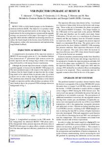
smallest internal vertical aperture in the SRS was 34 mm in the undulator vessel. Following extensive studies of the SRS with beam scrapers the internal aperture for the new insertion device vacuum vessels was set at 15mm [5]. A major consequence of the reduced aperture is that if the electron beam is mis-steered then the synchrotron radiation from the upstream dipole could illuminate the uncooled surfaces of the new ID vessel. The calculations of the temperature rise of the vessel in the worst case scenario show that the titanium vessel could melt in a few seconds with a 300mA, 2GeV beam. This temperature rise is so fast that it cannot be detected adequately by external thermocouples and so a beam interlock system has been installed that relies on vertical beam position monitors installed in the vessel itself [6]. Thermocouples are in fact installed on the external surface of the vessel as they will be able to detect more gradual rises in temperature such as that expected from grazing incidence synchrotron radiation striking the vacuum vessel. Very small limits of ± 2.4 mm have been imposed on the vertical beam position before the interlock dumps the beam by switching off the RF system. Such restrictive limits make operation of the SRS more difficult. For instance, ramping the beam energy now requires very close control of the beam orbit [7]. However, operation of the SRS has gone smoothly since the introduction of the new active interlock system with very few spurious beam losses caused by mis-firing of the trip system. 1.2 1.0 Normalised Lifetime
Abstract
0.8 0.6 0.4 0.2 0.0 0.0
1.0
2.0
3.0 Beam Position (mm)
4.0
5.0
6.0
Figure 1. Normalised beam lifetime measured as a function of vertical beam position at 600 MeV. The stored beam lifetime was predicted to be reduced by about 15% with the installation of the narrow gap vessel due to a reduction in the gas-scattering lifetime. The vacuum system has not yet recovered sufficiently since the installation to measure the new baseline lifetime of the SRS but lifetimes of greater than 25 hours at
571
200mA and 40 hours at 100 mA are already achieved routinely during operations. The lifetime has been measured as a function of beam position in the new vessel at 600MeV (figure 1). The results agree qualitatively with the expected shape of the lifetime vs position graph. The lifetime in the central part of the vessel changes slowly with beam position which agrees well with measurements taken at 2 GeV before the installation of the new vessel (figure 2). 60
Lifetime (hrs)
50 40 30 20 Equivalent Aperture of New Vacuum Vessel
10 0 0
1
2
3 4 5 6 7 Distance between Beam and Scraper (mm)
8
9
10
Figure 2. Variation of lifetime at 2 GeV with vertical aperture at the beam scraper before the installation of the new vessel.
3 PROGRESS WITH THE MULTIPOLE WIGGLERS
The magnetic material was supplied by Vacuumschmelze (Vacodym344) with the average remanent field for the main blocks being 1.28 T with an rms spread of only 0.3%. The spread in remanent field for the side pieces was even better at 0.2%. Vacuumschmelze also supplied the steel for the pole pieces (Vacoflux 50) which was measured to have a flux saturation of over 2.34T. The permanent magnet blocks and steel pole pieces were bonded into non-magnetic holders with some additional clamps provided for added security. Each of the fully assembled individual magnet arrays has been magnetically measured with a scanning Hall Probe to check the quality of the build (figure 3). The field was measured on the nominal electron beam axis at a distance of 10 mm from the pole surface. The results have been very encouraging with the peak field measured agreeing very well with the 3 dimensional modelling results carried out using Opera-3D with the actual measured parameters for the permanent magnet material included in the model (figure 4). The integrated vertical magnetic field has been found to be less than 10 G-m in all of the 4 arrays. This is an impressive result considering that the only block sorting that was carried out was the simple step of excluding the permanent magnet blocks with remanent field farthest away from the average values measured.
Two new high field multipole wiggler magnets are presently being manufactured and tested. The magnets are being built under a commercial contract by Sincrotrone Trieste to a CLRC design and specification. The design for the magnets was altered slightly from that already presented [8, 9] as the permanent magnet material used in the design was not available during the construction phase. A slightly lower remanent field material was used and this necessitated a slight increase to the dimensions of the side blocks to maintain a peak field of 2 T at the minimum gap of 19.2 mm. The final specification of the multipole wigglers is given in Table 1.
Peak Field on Axis Minimum Gap Period K Value Number of Full Strength Poles Pole Material Permanent Magnet Material Minimum Remanent Field Pole Dimensions Main PM Block Dimensions Side PM Block Dimensions Total Length of Magnet
2.0 T 19.2 mm 200 mm 37.4 9 Vacoflux 50 Vacodym 344 1.25 T 100 x 80 x 30 mm 130 x 120 x 70 mm 96 x 20 x 30 mm 1.078 m
Figure 3. Photograph of one of the assembled arrays undergoing magnetic testing.
Table 1. Specification of the Multipole Wigglers
572
their associated equipment, such as the waveguide and vacuum isolation valves. A second narrow aperture vacuum vessel will also be installed with another dedicated beam interlock system. Recommissioning of the SRS will begin in January 1999 with the two new beamlines complete by the end of 1999.
0.8 0.6
Magnetic Field (T)
0.4 0.2 0 -0.2
REFERENCES
-0.4 Theoretical Value -0.6
Measured Value
-0.8 0
100
200
300 400 Longitudinal Position (mm)
500
600
700
Figure 4. Comparison between calculated and measured magnetic field for one half of one array. One multipole wiggler is now complete and will undergo detailed mechanical and magnetic testing shortly (figure 5). Initial results indicate that the peak on-axis field will exceed 2 T at the minimum gap.
[1] J.A. Clarke and M.W. Poole, “Upgrading the SRS with Additional Insertion Devices and itsth Implications for the Storage Ring Layout”, Proc. 5 Euro. Part. Accel. Conf., Sitges, June 1996, p623. [2] E.M.H. Duke et al, “Beamline 14: A New Multipole Wiggler Beamline for Protein Crystallography on the SRS”, to be published in Proceedings of the Synchrotron Radiation Instrumentation Conference, Himeji, August 1997. [3] D.M. Dykes, “RF System thChanges Associated with the SRS Upgrade”, Proc. 5 Euro. Part. Accel. Conf., Sitges, June 1996, p1946. [4] N. Bliss and C.L. Dawson, “The Design, Construction and Testing of a Multipole Wiggler Magnet Titanium Vacuum Chamber for the SRS”, Proc. 1997 Part. Accel. Conf., Vancouver, 1997. [5] J.A. Clarke and H.L. Owen, “Operation of the Daresbury Synchrotron Radiation thSource with Reduced Vertical Aperture”, Proc. 5 Euro. Part. Accel. Conf., Sitges, June 1996, p620. [6] J.A. Balmer et al, “The SRS Multipole Wiggler Vacuum Vessel Protection System”, these proceedings. [7] S.F. Hill, “An Improved Closed Orbit Servo for Energy Ramps on the SRS at Daresbury”, these proceedings. [8] J.A. Clarke, “The Magnetic Design of a High Field Permanent Magnet Multipole Wiggler for the SRS”, Proc. 1997 Part. Accel. Conf., Vancouver, 1997.
Figure 5. Photograph of a fully assembled multipole wiggler.
4 FURTHER WORK
[9] J.A. Clarke et al, “Design of a 2 Tesla Multipole Wiggler Insertion Device for the SRS”, to be published in Proceedings of the Synchrotron Radiation Instrumentation Conference, Himeji, August 1997.
The two multipole wigglers are almost complete and will be fully tested before they are installed into the SRS in a shutdown towards the end of 1998. In the same shutdown all four RF cavities will be relocated along with
573