Propagation and Interference Issues in a 60 GHz Mobile Network Maxime Flament, Communication Systems group, Dept. of Signals and Systems Chalmers University of Technology, S-412 96 Gothenburg, Sweden
[email protected] ABSTRACT In the framework of the 4th Generation Wireless (4GW) Infrastructure project, the study of new air interfaces is needed to provide a broadband wireless infrastructure to mobile users. The 60 GHz frequency band presents a very large bandwidth that has been allocated to mobile communication. In this paper, propagation and interference issues in different environments are presented and analyzed to identify the air interface limitations for the deployment of 60 GHz networks. Simulations using a ray-tracing tool show the dynamics of the interference in chosen situations. The very short time variation scales underline the need of ad-hoc solutions, directional antennas, fast and intelligent IP handovers, and efficient network design. INTRODUCTION The millimeter waves are very attractive for broadband mobile telecommunication. Indeed, the 59-64 GHz frequency band has been internationally designated for unlicensed devices [1]. The study of a mobile system at this frequency should provide judicious design methods that will provide flexible and reliable mobility. For many reasons, such as limited emitted power, high temperature noise, and high oxygen absorption, the range of a millimeter-wave mobile system is relatively low. Layers of concrete or wood reflect the electromagnetic waves. Hence, channels in indoor and large area environments show strong multipath behavior. So, the millimeter wave propagation at these frequencies is usually confined within the rooms or open areas where the antennas are located. The band is therefore even more attractive for broadband mobile telecommunication since it allows better reuse of resources. However, in these environments, unacceptably strong interference situations occur frequently. Typically, in a single frequency network [2], users walking in a hallway will experience bursty interference yielding bad link quality and frequent need for handover. In dynamic situations, interference from other antennas can completely compromise the received signal, for example, while passing in front of an open door in a hallway. In this paper, we show that the Signal-to-Interference ratio can drop from 15 dB to 0 dB within a few centimeters. From the point of system flexibility, we assume that frequency reuse factors higher than one are not an acceptable solution to solve this problem. We assume OFDM modulation with a cyclic prefix long enough to
provide a modulation scheme that is able to reduce the effect of the strong multipath situation. However it does not mitigate the strong interference situation, nor reducing the number of handovers. The organization of the paper is as follows. The PCC-4GW working assumptions and link to other research are presented in next section. Two infrastructure scenarios are also described. We then introduce the channel behavior and the way we simulated it along user paths using ray simulation tools. Analysis of received and interference signals and examples of interference situations are discussed in the simulations section. The next section discusses the ways of mitigating the interference issues. Finally, conclusions and future work are presented. 4GW INFRASTRUCTURE The design of an infrastructure for mobile broadband communication is a real challenge. To start on a good basis, the PCC-4GW group has set up a series of working assumptions (WA) [3]. Below, the relevant WAs are recalled. The mobile system is supposed to provide up to 100 Mbit/s using unlicensed spectrum and ad-hoc techniques. The 60 GHz frequency band has been identified as one of the potential high-bit-rate bands. Even if the 4GW infrastructure is not only based on the millimeter wave band, particular effort should be provided to identify the limiting factors of such high carrier frequency. One of the important requirements in the design of the air interface is its flexibility. User deployed access points and self-planning capabilities are the underlying factors that will make the 4GW infrastructure economically viable. Indeed, public and private networks are expected to coexist, both offering high bit rate communication and broad range of commercial or noncommercial services. The 4GW infrastructure is meant to use technologies and backbone access that will be available around the year 2010. Therefore, we assume that the fixed infrastructure will be able to provide the required bandwidth to the users connected to the same access point. Assuming small cells and transmission up to 100 Mbit/s, a minimum requirement is for instance the 155 Mbit/s ATM technology. New emerging techniques, such as radio-over-fiber or IP-over-fiber, are good candidates to reach better system performance.
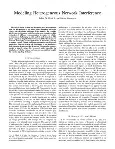
In [4], properties of typical large office and shopping mall environments are described. The first one is depicted in Figure 1. In such scenarios, the air interface has to deal with two major problems: the interference and the coverage issues. 3m
means that the loss can be approximated using the free space loss formula. Thus, assuming antenna gains of one, the received power PRx of the line-of-sight signal is given by
(PRx )dBm = (PTx )dBm − çç (4πr2 ) æ
è λ
2
ö
(1) dB
where PTx is emitted power, λ is the wave length (5x10⁻³ m), and r is the distance between transmitter and receiver. 18m
The received power PRx should exceed the receiver sensitivity. The receiver sensitivity includes thermal noise power N, shadow margin M and the needed signalto-noise ratio SNR for required performance:
(PRx )dBm ≥ N dBm + M dB + SNRdB Room situation Hallway situation Access point
Figure 1: Large office scenario and user pathways
(2)
Considering a signal with B=100 MHz bandwidth, the noise floor power is -94dBm, according to N=FkTB where T =290 K, k is the Boltzmann constant, and F=10 is the noise figure of the receiver.
This section is divided in three sub-sections: the coverage, the multipath, and the influence of the user's speed. While the coverage and multipath are relevant to this paper, we show that the speed of the mobile is not affecting our results.
The high penetration loss for most materials in the 60 GHz band is both advantageous, since it almost perfectly isolates closed rooms and limits interference, and disadvantageous, since any obstacle blocks the lineof-sight path or alternative paths and produces strong shadow fading. Therefore, the shadow-fading margin should be relatively high (10 dB). Finally, to achieve a BER of 10-3, we assume that we need an Eb/N0 higher than 10 dB. The emitted power PTx is limited by European regulations [6] to 100 mW EIRP (20 dBm). Using (1) and (2) yields finally an approximation of the range of a 60 GHz access point, which is r ≈ 20 m. Thus, in an office environment it is not likely to fall out of range except if the line-of-sight disappears. The system will be interference limited, and as we will see later the interference situations are typically bursty and difficult to predict. On the other hand, we will need at least 4 antennas to provide a reasonable coverage to a shopping mall. Coverage is the limiting factor. Interference situations are more predictable. However, we will show later that the shopping mall scenario is even more difficult to predict due to dynamics of the surrounding objects and people.
Coverage
Multipath channel
We assume here that distances involved in the 60 GHz system are small enough to ignore the effect of the oxygen absorption (14 dB/km) as showed in [5]. Furthermore, even if non line-of-sight could still provide a sufficient link quality, we consider line of sight propagation at 60GHz to calculate the coverage. This
The channel at 60 GHz has strong multipath behavior. Typical RMS delay spread in office room is 18 to 20 ns and excess delay spread for 30 dB attenuation is 70 ns [7].
The large office scenario is composed of a number of room and a hallway. The hallway is 3 meters wide and the rooms are six by six meters. The two user pathways that are depicted in Figure 1 are studied in this paper. The shopping mall scenario consists of a 20 meters by 40 meters large area surrounded by shops. Two stands are placed in the middle of the area. Propagation and interference issues in this scenario are discussed. CHANNEL DESCRIPTION To understand the underlying problems in designing a 60 GHz physical layer, one need to know how the channel behaves. We consider in this paper only single frequency networks, since the flexibility of the system is one of the main driving forces. However, the discussion could be extended to higher frequency reuse.
The Saleh-Valenzuela channel model, based on a double Poisson process, can be adapted to describe
Channel multipath is usually resolved by the use of an equalizer or by increasing the symbol time. OFDM makes use of FFT to form a signal constellation of high dimension and thus increase the symbol time. Using a cyclic prefix and a simple equalizer in the frequency domain, the multipath channel can be easily resolved. In this paper, the total power Pr,k received from the Access Point (AP) k is the integral in time of the simulated power delay profile (PDP) calculated from the incoming rays from this AP k. A new PDP is given for each position of the receiver. Note that the sampling rate of the signal is 200 MHz. Influence of the speed of the mobile In an OFDM transmission, large number of sub-carriers reduces sub-channels bandwidth but increases the symbol time and the dimension of the constellation. The frequency dispersion of the channel introduces an error floor and limits the performances of the system. This dispersion is also called the Doppler spread of the received signal because this effect is due to the Doppler shift of the rays coming from different directions when the receivers or the scatterers are moving. The error floor of an OFDM system is similar to the one of a single carrier modulation because we can consider each of the sub-carriers as a single carrier in a flat fading situation. (See e.g. [10].) The maximum Doppler frequency of a signal modulated on 60 GHz carrier is around a few hundred Hz at a normal walking speed (1 m/s). The normalized Doppler frequency compares this value to the bandwidth of a sub-carrier. This is to say that if we use a 200 MHz bandwidth and 1024 OFDM sub-carriers, the normalized Doppler frequency is around 10-3, for which the error floor is lower than 10-9. Thus, the Doppler spread has no substantial influence on the performance and we can consider in the spatial simulation of our channel that the speed of the mobile can be neglected.
RAY-TRACING TOOL The ray-tracing tool is called Radio Propagation Simulator (RPS). RPS is a ray optical wave propagation model. It allows the determination and analysis of wave propagation characteristics in indoor environments. It has been specially designed for 60 GHz network analysis. For example, it was used in the MEDIAN European research program to simulate ATM LANs at 60GHz. Time variation along a user pathway Figure 1 above depicts two typical paths that a mobile user connected to one base station could take. Incoming rays are calculated at evenly spaced points along these paths. The distance between the points is determined by the spectral properties of the time-varying multipath channel. The stronger multipath, the closer the points should be to keep a sufficient correlation of the channel impulses between successive points along the user pathway. The short-term spectral analysis of the received power shows whether we should increase the rate of the points on the path. The incoming rays arriving within one sampling interval are added together. The phase of the incoming rays is uniformly distributed. Thus, the amplitude of the total received power is varying along the path. Figure 2 shows a short sample of the simulated time-varying channel. −75
−80
Received Power [dBm]
statistically the time of arrival and complex value of the rays [8]. This model assumes that the received signal rays arrive in clusters. The rays have independent uniformly distributed phases. They also have independent Rayleigh distributed amplitudes whose variances decay exponentially with cluster and ray delay. The cluster and the rays within a cluster form Poisson arrival processes that have different but fixed rates [9]. Depending on the type of antenna, the power delay profiles have different properties. As the direction of arrival of the rays is correlated with the cluster, the rate of cluster arrival drops dramatically when the antenna gains increase.
−85
−90
−95
3.8
3.85
3.9 3.95 Distance from Access Point [m]
4
4.05
Figure 2: Received power 4 meters from hallway antenna Single frequency network assumption To emphasize the effect of the interference, we considered in the simulations that any rays coming from a different antenna are contributing to the interference power. This would be the case in a loaded single frequency network using code or time division multiple access. In next section, we identify the interference situations along the two proposed path.
SIMULATIONS
25
Hallway situation
20
15
10
SIR [dB]
The simulation results are based on the time variation of the received power from the connected antenna (PRx) and the signal-to-interference ratio (SIR). Three situations are described in the following sub-sections: the Hallway, the Room and the Shopping mall.
5
0
For this situation, the PRx value was simulated every 2.5 mm. This distance is half the wavelength and was shown to be short enough to keep a strong correlation between consecutive points. Short-term spectral analysis shows that the bandwidth is far below the sampling rate of the channel measurement. The user along the hallway experiences large variation of the SIR. Figure 3 shows the SIR along the Hallway path ranging from almost no interference to -20 dB.
30
SIR [dB]
20
−5
−10
−15
1.84
1.86
1.88 1.9 1.92 distance from Access Point [m]
1.94
1.96
1.98
Figure 4: Example of fast varying SIR along the hallway path A large number of crossings along with short interference duration might initiate bad hand-over decisions. Moreover, [11] is investigating the IP handover latency and shows that 0.1 second is needed to make an IP handover using pre-registration (30 seconds without pre-registration). 0.04
10
0.035
0
Level Crossing Rate
0.03
−10
−20
0.025
0.02
0.015
1
1.5
2
2.5 3 3.5 4 4.5 distance from Access Point [m]
5
5.5
6
Figure 3: SIR along the hallway path
0.01
0.005
However, the problem is not the range of the SIR values, it is its occasional rapid change within a short distance (or short period of time). Figure 4 shows that the SIR between adjacent small areas varies very fast. We can see a first drop from 20 dB to -5 dB within 2 cm, followed by a 20 dB raise then coming back under 0 dB after 1 cm. One could argue here that we actually have, for each channel measurements (2.5 mm), approximately 200 000 samples (at 1 m/s), which correspond roughly to 2000 OFDM symbols (with FFT size 1024). It means that during this time we might have enough time to report a new interference and change channel or base station. So, the interference signal detection will have to be fast. However, fast handovers might not always be a good solution. Indeed, an analysis of the level crossing rates shows that most of the level crossings happen around 0 to 3 dB, where the handover decision should be made.
0 −15
−10
−5
0
5
10 SIR [dB]
15
20
25
30
35
Figure 5: Level Crossing Rate of the SIR signal along the hallway path Room situation In a room, the multipath situation is much worse than in the hallway. Third order reflections contribute to the multipath. Hence, the variation of the channel is faster. Distance between the simulated points was chosen as 1 mm, which was shown to be enough. On the other hand, a nicer interference situation is observed for users walking out of a room. This situation shows a normal handoff case issue. However, the user going out of a room will still be connected to its room BS. He will arrive in a 2 dB to 4 dB SIR area. The MAC will then not trigger the handover directly. But once the
path passes out of the LOS of his assigned base station (continues in the hallway), the signal is immediately lost and a fast handoff procedure has to be initiated. This shows the difficulty to predict handover procedures. Shopping mall situation The shopping mall situation is more difficult to predict since the dynamics of a user is difficult to predict and simulate. The channel is much more dependent on the people and moving objects surrounding the users. Due to computer limitation, a time-varying channel was not simulated. We can anyway extend the discussion from the previous observations. In a previous section, we showed that coverage is the limiting factor. Indeed, interference situations are more predictable if we consider the mobile user and the network only. Thus, we need to consider the density of people in the shopping mall as a coverage limitation factor. Coverage and interference burstiness is in this case mainly due to movement of bodies around the user. In [12], the limitations of millimeter wave systems due to body shadowing are presented. CONCLUSIONS In this paper, we discussed the propagation and interference issues in a 60GHz system. We showed that coverage is not the main limitation in offices, but, on the other hand, the interference can be bursty and create unstable handover situations. Using a ray tracing simulated channel, we have presented the dynamics of the 60 GHz time varying channel in particular situations for typical office environments and we extended it to the shopping mall situation. The results give an insight on the time variations of the SIR. However, the simulations were based on a single frequency network and omnidirectional antennas. Using directional antennas, dynamic resource allocation, or faster handover will decrease the interference issues but the problems due to the short-time variation of the interference will always remain more difficult to handle than in lower frequency bands. The time varying channels that have been described and simulated can be used for future investigation of the transmission of OFDM signals in a realistic situation. Virtual Cellular Networks [13] (VCN) or Synchronous Coherent OFDM [14] may provide valid air interface solutions to the presented issues and will be investigated. The simulations provide also hints about the handover issues and error correction and ARQ strategies that are going to be studied by other WPs within PCC.
ACKNOWLEDGEMENT The author would like to acknowledge the Radio Communication group at KTH who provided the raytracing tool. This paper has been written in the framework of the 4GW project within the PCC strategic research program.
REFERENCES [1] "Radio Regulations", RR-98, ITU, 1998. [2] J. Voigt, J. Hübner, E. Förster, G. Fettweis, "Design Pattern for a Single Frequency TDMA-System in a Typical Office Environment at 60 GHz", IEEE 49th Vehicular Technology Conference, 1999, pp.1570-1574. [3] M. Flament, F. Gessler, F. Lagergren, O. Queseth, R. Stridh, M. Unbehaun, J. Wu, J. Zander, "An Approach to 4th Generation Wireless Infrastructures – Scenarios and Key Research Issues", IEEE 49th Vehicular Technology Conference, July 1999, pp. 1742-1746. [4] M. Unbehaun, M. Flament, "Technical Scenarios for 4GW", Internal report, S3/KTH, Stockholm, April 1999 [5] P.F.M Smulders, "Broadband Wireless LANs: A feasibility study", Ph.D. thesis, 1995. [6] "Relating to the use of short range devices (SRD)", CEPT/ERC Recommendation, CEPT/ERC/REC 70-03 E, Tromsø, 1997. [7] J. Hübner, S. Zeisberg, K. Koora, A. finger, “Channel model for 60 GHz indoor wireless LAN Design Based on Complex Wideband Measurements”, IEEE 47th Vehicular Technology Conference, 1997, pp. 1004-1008. [8] J.-H. Park, Y. Kim, Y.-S. Hur, K. Lim, K.-H. Kim, "Analysis of 60 GHz band indoor wireless channels with channel configurations", IEEE International Symposium on Personal, Indoor and Mobile Radio Communications, 1998. pp. 617-620. [9] A. Saleh; R. Valenzuela, "A statistical model for indoor multipath propagation", IEEE Journal on Selected Areas in Communications, Feb. 1987. [10] Pål Frenger, "Multicarrier Modulation and coding for Multichannel Systems", Lic. thesis, Chalmers, 1997. [11] Jiang Wu, "An IP Mobility Support Architecture for the 4GW Wireless Infrastructure", PCC Workshop, Lund, 1999. [12] Matthias Unbehaun, Jens Zander, "Indoor coverage for wearable devices with user deployed access point", PCC Workshop, Lund, 1999. [13] H. J. Kim, J.-P. Linnartz, "Virtual cellular network: a new wireless communications architecture with multiple access ports", IEEE 44th Vehicular Technology Conference, 1994, pp. 1055-1059. [14] K. L. Baum, "A synchronous coherent OFDM air interface concept for high data rate cellular systems", 48th IEEE Vehicular Technology Conference, 1998, pp. 2222-2226.