PV inverter control using a TMS320F2812 DSP Tamás Kerekes, Dezső Séra, Remus Teodorescu
[email protected];
[email protected];
[email protected]; Institute of Energy Technology; Aalborg University Pontoppidanstraede 101 DK-9220, Aalborg, Denmark It is implemented using the delta operator [2], which gives better performance for 16 bit variables than the shift based This paper presents the implementation of a control system of an implementation. The tested MPPT methods are the Perturb & inverter for grid connected photovoltaic (PV) applications, using a Observe (P&O) and Incremental Conductance (INC) algorithms. low cost TMS320F2812 eZdsp board. The implemented control The Simulink model of the control scheme is presented below: system contains a P+Resonant current controller, a Maximum Power Point Tracker (MPPT) to optimize the power extraction from the PV panel, and a Phase Lock Loop (PLL) for grid synchronization. The whole control was implemented in fixed point using Simulink. Code Composer Studio is successfully used as a flexible user interface for controlling and monitoring the process. The experimental results show that this low cost DSP is capable of running a complex control structure in real time at a high sampling rate. In this case a current THD close to 1% and a high efficiency MPP tracking has been achieved. 1.1 Introduction
round(75e6/8192/2)
[Ugin]
Ug
[Igin]
Ig
Duty cy cle
round(75e6/8192/2)
W1
F2812 eZdsp
C28x PWM
[START]
W2
[Udcin]
Udc
C28x PWM
EN
[Idcin]
Idc
[ThetaGrid]
Aquisitions
Control
1.2 Control scheme
1
= Vu * 2^ y = Qu > Ey = Eu + 5
W2 C28x PWM
= Vu * 2^ y = Qu >> y = Eu + 1
W3
[sintheta]
C28x PWM_B
A PV inverter converts the DC power produced by solar panels to Fig. 2 The Simulink scheme of the single-phase MPPT control grid synchronized AC power. A simplified scheme for the whole control can be seen on Fig. 1. 1.3 DSP Implementation
÷
Simulink is a very flexible tool for dynamic simulation. Together with RTW, the Embedded Target for TI C2000 compiles the model, generating a real-time C-code, which is forwarded to CCS. The DSP code is generated automatically and downloaded to the DSP by CCS, which is also used to debug the code and to monitor and observe the variables. This process can be visualized as:
×
×
sin (θ
)
Fig. 1 Scheme of the implemented control strategy
The three main parts are represented by the current controller, the MPPT and the PLL. The input of the current controller is the error between the measured and reference grid current (ig ref and ig). In order to synchronize the injected grid current with the grid voltage (to achieve unity power factor), the phase of the reference current is taken from the grid voltage, calculated by the Phase Lock Loop (PLL) block. The current controller output is the reference grid voltage, which divided by the DC source voltage gives the duty cycle for the inverter. The current controller is a P+Resonant controller [1] capable of zero steady state error for a sinusoidal reference signal. The transfer function presented below, where ω0 represents the resonance frequency of the integrator: s H PR = K P + K I 2 s + ω02 (1.1)
Fig. 3 Illustration of the Simulink and RTW interaction with CCS for real-time implementation (source: http://www.mathworks.com/products/tic2000)
The Simulink model was implemented in fixed point, choosing a sampling frequency of fs=8192Hz. A value of power of 2 has been chosen in order to optimize the operation where multiplication with the sampling period (e.g. integration) is needed. The frequency of the output pulses is defined by the waveform period from (1.2) and it can be calculated using the following formula: f PWM =
f HSPCLK 1 75e6 1 ⋅ = ⋅ = 8192Hz (WAVEFORM PERIOD) 2 75e6 ( 2 ⋅ 8192) 2
(1.2) where fHSPCLK is the frequency of the high-speed peripheral clock. The ½ term is used due to the symmetrical PWM. The CCS is used for debugging and online visualization of the essential variables. This can be done either directly viewing the
value of the variable in the watch window, or plotting it on a graph current harmonics level but still does not comply with the window, as shown on Fig. 4. standard. A drastic decrease in the THD can be seen when the compensation for the 5th harmonic is turned on, the THD decreases to 2.2%, well below the limit in the IEEE standard. Turning on the compensation for the 7th harmonic, a further improvement of the grid current waveform quality is achieved, resulting in a THD of 1.2% Grid voltage 400
Vg [V]
200 0 -200 -400
0
0.005
0.01
0.015
0.02
0.025
0.03
0.035
0.04
0.025
0.03
0.035
0.04
Grid current 20
Ig [A]
10 0 -10 -20
Fig. 6 Current THD for different cases of harmonic compensation
Fig. 4 The Code Composer Studio environment
0
0.005
0.01
0.015
0.02 time [s]
Fig. 7 Grid voltage and grid current for a 10A peak current reference
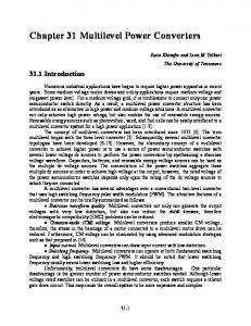
The MPP tracker was also tested and the results can be seen on Fig. 8. The MPP was reached at 1300W and the oscillations at the maximum were around ±20W, due to the noise in the measurements.
1.4 Hardware setup
Fig. 8 Tracking of the MPP using 16 BP-MSX120 solar panels
1.6 Conclusion
Fig. 5 The Green Power Inverter hardware setup
The picture in Fig. 5 presents the laboratory setup and is detailed below: • PV Simulator, which serves as the input voltage for the inverter, with a voltage range of 400-650V. It is realized with two Delta Elektronika 300-5 300V/5A power supplies. The system also can be connected to the available 1.5kW solar array. • A three-phase 400V/5.5A 1.5kW Danfoss VLT 5005 inverter. In the case of single-phase configuration only two legs of the inverter bridge are controlled by the two PWM signals generated by the DSP. • An LC filter, which, together with the transformer inductance forms an LCL filter, and provides the filtering of the PWM output voltage from the inverter in order to apply it to the grid, through the transformer. • A Voltech three-phase power analyzer • The PWM pulses for the inverter control are generated by a Spectrum Digital TMS320F2812 eZdsp card, featuring a TMS320F2812 32 bits DSP from Texas Instruments. 1.5 Results Without any harmonic compensation the grid current THD was above 10.5%, which does not fulfill the IEEE 929 standard. Turning on the compensation for the 3rd harmonic, decreases the
The current controller with selective harmonic compensation, together with the MPPT algorithms have been successfully implemented on the TMS320F2812 eZdsp board using Simulink RTW, Embedded Target for TI C2000 family and CCS. Even with a complex control system it was possible to run it at 8kHz sampling frequency. Results show that the harmonic compensation works well resulting in a low current THD (THDi=1.2%), well within the requirement of the IEEE 929 standard. Together with the current controller, the MPP tracker is also running and is capable of tracking the MPP of the PV panel, having 3% power oscillations at the maximum. The C28xx family proves to be a very good low cost solution for PV inverter applications. References: [1]. R. Teodorescu, F. Blaabjerg: A new control structure for grid-connected LCL PV inverters with zero steady-state error and selective harmonic compensation, IEEE 2004 [2]. Michael J. Newman, Donald G. Holmes: Delta Operator Digital Filters for High Performance Inverter Applications, IEEE Transactions on Power Electronics, vol. 18, no.1, Jan.2003 [3]. Chihchiang Hua, Jongrong Lin, Chihming Shen: Implementation of a DSPControlled Photovoltaic System with Peak Power Tracking, IEEE Transactions on industrial electronics, Vol. 45, No. 1, Feb.1998. [4]. TMS320x281x DSP Event Manager (EV) Reference Guide; Literature no: spru065c. Source: http://focus.ti.com/lit/ug/spru065c/spru065c.pdf (pg 60)