Latest Trends on Circuits, Systems and Signals
TMS320F2812 DSP Controller for Dynamic Voltage Restorer (DVR) Application for Improving of a Three Phase Inverter R.Omar And N.A Rahim
[email protected] This paper discusses a control technique improvement of a three-phase inverter using TMS320F2812 DSP controller for Dynamic Voltage Restorer (DVR) applications. The output of the inverter is then connected to a voltage grid via a second order filter and injection transformer. The Control algorithms are developed using TMS320F 2812 DSP. The proposed technique achieves voltage regulation with low total harmonics distortion (THD) for both voltage and current. This paper also highlights a series of discussion, analysis and studies performed on the proposed control technique, including L-C filter design issue. An analysis and experimental results validate the effectiveness of the proposed control solution.
sinusoidal ac voltage with low voltage THD and fast transient response under load disturbances. Another important aspect of power quality is harmonic distortion. General requirements for harmonic distortion can be found in standard [4] and particularly for connection of distributed resources to grid in [4]. PWM control is the most powerful technique that offers a simple method for control of analog systems with the processor’s digital output [5]. With the availability of low cost high performance DSP chips characterized by the execution of most instructions in one instruction cycle, complicated control algorithms can be executed with fast speed, making very high sampling rate possible for digitally-controlled inverters [6]. Fig.1, shows the configuration of the DVR consists an inverter, series or injection transformer, an inverter, control system and energy storage. The main function of a DVR is the protection of sensitive load from any disturbances coming from network. In this paper, a three-phase voltage will be generated through the proposed control using TMS320F2812 DSP. The voltage produced by the inverter must be controlled in order to be in phase with the disturbance in main voltage or supply.
Keywords—TMS320F2812 DSP, inverters, Dynamic Voltage Restorer (DVR), Total Harmonic Distortion (THD), Filter
I. Introduction Electronics devices hold substantial promise for making distributed energy applications more efficient and cost effective. There is a need to develop advanced power electronics interfaces for the distributed applications with increased functionality (such as improved power quality, voltage/volt-amperes reactive (VAR) support), compatibility (such as reduced distributed energy fault contributions), and flexibility (such as operation with various distributed energy sources) while reducing overall interconnection costs. The use of voltage source inverters is increasing [1]. They are used both for feeding power from distributed generators to the transmission grid and power to various types of electronic loads. In recent years, the number of different power resources connected to power systems (voltage grids) has increased and there has been a move toward connecting small power resources to the medium and low voltage network [2]. Power quality standards for connection of an inverter to the grid are still under development, since previously there have been a few similar high power applications. In [3] it is stated that the power quality is determined by the voltage quality, when the voltage is a controlled o variable. In order to deliver a good ac power the controlled pulse width modulation (PWM) inverter and L-C output filter have to convert a dc voltage source (e.g. batteries) to a
ISSN: 1792-4324
This paper presents in detail the control systems of inverter in order to produce inverter output for DVR application using Texas Instruments Microcontroller (TMS320F2812). TMS320F2812 is a new generation of controller with a main frequency of 150MHz. The speed and features of this DSP make it an excellent choice for the digital control of an inverter. The modules that are used in implementing the control of an inverter and the step involved in programming the control algorithm will also be discussed. Experimental results obtained from inverter output will be presented. The implementation of a control system of an inverter for Dynamic Voltage Restorer applications uses a low cost TMS320F2812eZdsp board.
21
ISBN: 978-960-474-208-0
Latest Trends on Circuits, Systems and Signals
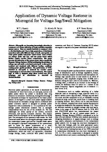
Fig. 3. The frequency response curve of the LC filter The filter calculation is done by setting the inductance value to L= 3.947mH and admitting resonance frequency equal to 1 kHz, as the equations below:
Fig. 1. Inverter connected to a grid via filter and injection transformer
II. Inverter’s Output Filter Design Dimensioning
(2) (3)
Fig.2 shows the LC filter for a DVR system where transfer function can be described as (1). The frequency response curve of (1) is shown in Fig.3. From the figure, it is recognized that the filter has desirable characteristics near fundamental frequency region.
So C = 6.417 uF
III. Proposed Voltage Controller Using TMS 320F 2812 DSP TMS320F2812 is a new generation controller with main frequency of 150MHz. It has 12-pulse Width Modulation (PWM) output and 12-bit analog to digital converter. The fast conversion period, which is about 80ns, is very suitable for real time sampling. In this study, eZdsp F2812 DSP board is used for PWM control application [5]. The application of the PWM algorithm requires a time reference, a comparison mechanism, and digital outputs. Event Manager Modules of the DSP have the General Purpose (GP) Timer that can be used as time reference, Full Compare/PWM Units as a comparison mechanism, and have dedicated digital PWM outputs. The principles of Event Manager Modules and PWM signal generation process are comprehensively described in the following sections. There are two event manager modules in TMS320 F2812 called EVA and EVB. TMS320 F2812 has six independent pairs of PWM outputs; three of which are controlled by EVA and the other three are controlled by EVB [5]. In the study, GP Timers, Full Compare/PWM Units and PWM outputs are used to generate the gating pulse for the power circuit. There are two general purpose (GP) timers that can work independently from each other. GP Timer1 and 2 are controlled by EVA, GP Timer3 and 4 are controlled by EVB. These timers are used to provide a time base for the operation of compare units and associated PWM circuits to generate the PWM outputs [6]. Each GP Timer has up down counter TxCNT, compare register TxCMPR, period register TxPR, control register TxCON, and direction input TDIRx registers. The simplified block diagram of
Fig. 2. LC filter for a DVR system =
ISSN: 1792-4324
(1)
22
ISBN: 978-960-474-208-0
Latest Trends on Circuits, Systems and Signals
GP Timer is shown in Fig. 4. There are six compare units as shown in Fig.5, three of which are in EVA module and the other three are in EVB module. These registers depend on the associated GP Timers to generate PWM signals. The generation of PWM patterns comprises the following steps: counting mode, GP Timer compare operation, and carrier signal generation. Details of each step are mentioned below. There are two counting modes, controlled by the content of TxCON register that can be applicable to generate the carrier signal: continuous count up mode results in asymmetric and continuous count up down mode results in symmetric carrier waveform. The timer values are incremented by one for each GP Timer clock pulse [7].
Fig.5. Event Manager Block Diagram Fig. 6, shows the algorithm of the DSP code for PWM generation. At each sampling interval,the interrupt loop is repeated.
Fig. 4. PWM signal generation using EV
Fig. 6: Flow chart of the control implementation
IV. Experimental The control circuit section is composed of three parts, namely PC, DSP board and IGBT driver. TMS320F2812 eZdsp is programmed to produce Gate pulses by comparing a triangular carrier wave in 5-KHz and a sinusoidal reference wave in 50-Hz. The reference wave amplitude adjusts the frequency of the generated AC voltage.
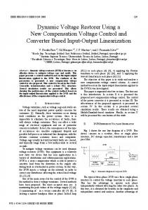
The basic circuit diagram of the DSP controlled three-phase inverter is shown in Fig.7. Experimental setup procedure can be divided into two sections, i.e., the control and power circuit. Electrical isolation between control circuit and power circuit is provided by the optically coupled devices. A. Control Circuit Design
ISSN: 1792-4324
23
ISBN: 978-960-474-208-0
Latest Trends on Circuits, Systems and Signals
Fig. 7. DSP controlled Three -phase PWM inverter B. Power Circuit Design Fig. 8. Experimental set-up consists of three phase inverter, DSP and filter scheme
The power circuit section is composed of four parts, namely full bridge inverter circuit, DC power supply, LC filter and load. PWM inverters include semiconductor devices with nonlinear characteristics and can generate dominant harmonics in the system. The waveform quality of the sensitive load is improved by putting an LC filter at the output of the PWM inverter. In order to design an LC filter, there are many methods available. Optimum performance can be obtained by using [6].
V. Results And Discussion The experimental setup as shown in Fig. 7, is composed of PC, DSP board, IGBT driver circuit, full bridge inverter circuit, DC power supply, LC filter, and oscilloscope (shown in Fig.10). The proposed system is designed to provide a 50-Hz sinusoidal waveform on the load with varying carrier signal 5 KHz). The sampling frequency of the DSP controller is set at 5-KHz. The design parameters of the test device are shown in Table 1.
(a)
Table1: Main Specification Of The DVR PARAMETER Nominal grid voltage Nominal load voltage Switching/sampling frequency
VALUE 120V (L-L) 120V(L-L) 5 KHz
Max. inverter dc-bus voltage Capacitor of dc- bus Filter inductance Filter capacitance
120 V 26uF 3.947mF 6.417uF
(b)
ISSN: 1792-4324
24
ISBN: 978-960-474-208-0
Latest Trends on Circuits, Systems and Signals
Fig. 10.Three phase voltages at Inverter Output
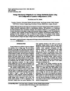
(c) Fig. 9(a),(b) and (c ). The line voltages of phase A, B and C before connecting to the filter.
Fig. 11. Harmonic spectrum of the phase voltage
Fig. 10. The line voltage of phase A ,B and C after connecting the filter
ISSN: 1792-4324
Fig. 12. Harmonic spectrum of the phase current
25
ISBN: 978-960-474-208-0
Latest Trends on Circuits, Systems and Signals
[2] [3]
[4]
[5]
[6] [7]
Fig. 13. Current at each inverter
IEEE Std. 1159 – 1995, “Recommended Practice for Monitoring Electric Power Quality”. IEEE Industry Applications Society Power Engineering Society, IEEE Recommended Practices and Requirements for harmonics control in electrical power systems. Piscatway,NJ: IEEE, 1992 T. Kawabata, T. Miyashita and Y.Yamamoto “Dead beat control of three phase PWM Inverter, IEEE Trans, Power Electro, vol 5, pp. 21-28 Jan. 1990 A. Ghosh and G. Ledwich, “Power Quality Enhancement Using Custom Power Devices,” Kluwer Academic Publishers, 2002. TMS320C281x Event Manager Reference Guide (SPRU065), Texas Instrument. TMS320C281x Analog to Digital Converter Reference Guide (SPRU066), Texas Instrument.
A prototype consists of three-phase Inverter and filtering scheme has been developed as shown in Fig. 8. Fig. 9(a) (b) and (c) show the phase voltage before connecting the filter. The output of the phase voltage after connecting filter is shown in Fig. 10. THD for the voltage and current are shown in Fig. 11 and Fig. 12 respectively. Fig. 13, shows the balance currents after load connection.
VI. Conclusion This paper presents the analysis and design of a digitally controlled three-phase PWM inverter based on DSP control application in order to generate three-phase voltage for dynamic voltage restorer application. The basics of software optimization and hardware installation for proposed system have been presented in detail. The detailed architecture and signal processing components of the eZdsp F2812 from Texas Instruments have been clearly described. The proposed technique achieves voltage regulation with low total harmonics distortion (THD) for both voltage and current. The very close agreement of experimental results illustrates the efficiency, accuracy and dynamic response of DSP based PWM inverter design. Three-phase voltages produced by inverter will be used to inject the missing voltage through injection transformer which will be discussed in the next paper.
Acknowledgement The authors wish to thank UM and UTeM for providing grant under grant PS002/2009C for this project.
References [1]
M. H. Bollen, Understanding Power Quality Problems, Piscataway NJ; IEEE Press, 2000
ISSN: 1792-4324
26
ISBN: 978-960-474-208-0