Q-SCA: Incorporating QoS Support into Software Communications Architecture for SDR Waveform Processing* Jaesoo Lee, Saehwa Kim, Jiyong Park, and Seongsoo Hong Real-Time Operating Systems Laboratory, School of Electrical Engineering and Computer Science, Seoul National University, Seoul 151-742, Korea {jslee, ksaehwa, parkjy, sshong}@redwood.snu.ac.kr Abstract The Software Communications Architecture (SCA) defined by Joint Tactical Radio Systems (JTRS) is the de facto standard middleware currently adopted by the Software Defined Radio (SDR) Forum, and is widely accepted as a viable solution to reconfigurable component-based distributed computing for adaptive wireless terminals and base stations. While SDR is heavily involved in real-time signal processing, the current SCA lacks QoS capabilities in terms of both QoS specification and enforcement. In this paper, we propose Q-SCA (QoS enabled SCA) to address this problem. Specifically, we present an application model for SDR waveform software, and then extend the SCA core framework for QoS specification and enforcement. Q-SCA supports QoS capabilities by (1) providing a QoS descriptor that is backward compatible with SCA’s original domain profiles, (2) offering services for admission control and resource allocation that are used throughout the application instantiation process, and (3) introducing a mechanism to enforce the result of the resource allocation. We have fully implemented Q-SCA and performed measurements to quantify its run-time performance. Our implementation clearly shows the viability of Q-SCA. Keywords: QoS, software communications architecture, software defined radio, resource allocation
1. Introduction The convergence of the Internet and wireless communication technologies has created a huge demand for access to Internet services from wireless consumer devices such as smart phones, smart pads, and mobile home service robots. Unfortunately, this wireless connectivity is achieved by a disparate array of hardware implementing a number of different wireless protocols. World-wide, there already exist dozens of cellular and data communication standards, and several new wireless standards are currently waiting for approval. When a
*
This paper is an extended version of the paper “Extending Software Communications Architecture for QoS Support in
SDR Signal Processing” that appeared in the 11th IEEE International Conference on Embedded and Real-Time Computing Systems and Applications.
Application (signal processing part)
SCA Code Framework
Admission Controller
Resource Allocator
Real-Time Object Request Broker (RT-CORBA)
Operating Environment (control part)
COTS Real-Time Operating Systems (POSIX)
Figure 1. Structure of SCA software (Gray-colored modules are Q-SCA components). new standard is put into use, consumers are forced to replace their wireless devices since support for the new standard requires a new modem. Software defined radio (SDR) is a viable solution to this problem since it is a software configurable modem that offers wireless Internet users with the ability to use a single terminal to access a wide range of wireless services by ensuring that handheld devices are modem-agnostic. Often, SDR modem hardware makes up a distributed platform consisting of heterogeneous microprocessors, microcontrollers, and digital signal processors interconnected by shared communication buses. To facilitate communication among these nodes, the SDR Forum approved the JTRS Software Communications Architecture (SCA) [1] as standard middleware for SDR. Figure 1 shows its overall structure. It consists of an operating environment and applications. The applications include signal processing and protocol processing code for RF communication. The operating environment has two layers: the COTS (commercial off the shelf) layer that controls CPU scheduling, resource allocation, and communication and the core framework layer that manages the life cycle of waveform applications. Unfortunately, SCA does not currently support any QoS guaranteeing features since it is focused only on runtime reconfigurability via dynamic component deployment. For QoS support, the current SCA specification recommends using dedicated co-site mitigation hardware [2], defining a proprietary API that utilizes dedicated transfer mechanisms [3], or exploiting the QoS features of the underlying CORBA object request broker (ORB) [4] or real-time operating system (RTOS) in the COTS layer of the operating environment. However, we argue that the SCA core framework is the best candidate for supporting QoS capabilities since (1) applications and their components are totally specified in a set of XML profiles and (2) the domain management and service parts of the SCA core framework manage all resources available in a given distributed system. Motivated by this, we develop a QoS-enabled SCA, named Q-SCA, by extending the current SCA framework. It can provide timesensitive signal processing applications with QoS specification, admission control, and resource reservation. To do so, we develop a novel waveform model capable of describing SDR waveforms in a flexible way. We extend
the core framework of SCA and its domain profiles to support our application model which is focused on wireless applications. As a result, Q-SCA supports QoS capabilities by (1) providing a QoS descriptor that is backward compatible with SCA’s original domain profiles, (2) offering services for admission control and resource allocation that will be used throughout the application instantiation process as shown in Figure 1, and (3) introducing a mechanism to enforce the result of the resource allocation. We have already developed an SCA v. 2.2 compliant implementation called SNU-SCA and applied it to a military SDR handset. We exploit this experience in designing Q-SCA as an extension to SNU-SCA. We have completely implemented it and performed extensive measurements to quantify its run-time performance. Our implementation clearly shows the viability of Q-SCA.
1.1. Related Work Our research is strongly motivated by recent advances in highly reconfigurable software radios and QoSenabled middleware technologies. The term software defined radio was coined in 1991 to describe radio devices implemented in software and running on generic hardware. Since then, SDR technology has evolved to offer improvements in flexibility and upgradability for software-programmable radio systems. It is now widely accepted as an enabling technology for fourth generation (4G) cellular wireless communications in that a single handset can operate with diverse wireless protocols using common general purpose hardware. At the heart of SDR technology lies an efficient, interoperable, and standardized software framework such as the Vanu software radio architecture [5][6], E2R beyond 3G systems [7], and JTRS SCA. All of these frameworks aim at fulfilling the functional and operational requirements of SDR. They invariably provide implementation independent description languages for specifying interfaces and configurations of waveform applications. They also offer mechanisms that translate the descriptions into implementation-specific operations while providing source-level portability. However, all of them lack support for QoS, thus passing to application programmers the full responsibility of guaranteeing QoS requirements. This will lead to poor resource utilization and more severely, deteriorated radio performance. To the best of our knowledge, Q-SCA is the first attempt to incorporate QoS issues into the SDR software framework. In the meantime, there have been numerous research results on middleware that supports QoS. Such examples include 2KQ [8], Agilos [9], TAO [10], and QuO [11]. Each of them provides a method for application programmers to describe QoS requirements along with a mechanism for enforcing those requirements. For example, in 2KQ and TAO, system-level QoS parameters are derived from high-level QoS requirements, and resources are allocated according to the derived parameters. Agilos is different in a sense that it uses a besteffort scheduling policy instead of reserving resources. In QuO, application programs have the responsibility to enforce QoS. However, these middleware systems are mostly aimed at general purpose distributed applications and differ from Q-SCA which is specialized for dynamically reconfigurable real-time signal processing applications in the SDR domain. On the other hand, Q-SCA is complementary to these technologies since it can
utilize the QoS enforcement and adaptation mechanisms developed in the context of multimedia applications. Specifically, Q-SCA relies on the real-time and QoS capabilities of TAO [10]. The remainder of the paper is organized as follows. Section 2 overviews the original SCA specification and gives the implementation status of SNU-SCA. Section 3 proposes a formal design model for SDR waveform applications. Section 4 presents QoS descriptors to specify the QoS requirements of the proposed waveform model. It also explains the admission control and resource allocation mechanisms and their enforcement. An explanation of the modified application initiation process follows so as to show how these extensions can guarantee the desired QoS requirements of each application. In Section 5, we introduce our Q-SCA implementation and report on its run-time performance. We conclude this paper in Section 6.
2. Overview of SCA and SNU-SCA To aid in understanding the rest of this paper, we present an overview of the original SCA and give the implementation status of SNU-SCA. SCA is defined in terms of a set of common interfaces for SDR waveform applications. These interfaces are grouped into two parts: (1) the standard waveform component interfaces and (2) the standard operating environment (OE) interfaces. The former defines APIs between signal processing components such as filters, modems, decoders, digitizers, etc. The latter defines APIs that developers use to dynamically deploy and control applications and to exploit services from underlying platforms. Since standard waveform component interfaces are made for ensuring interoperability among components, they have little relationship with QoS. Thus, we concentrate on the OE interfaces in making SCA aware of QoS. The OE consists of the core framework (CF) and the COTS software. Since the latter is composed of an RTOS and a CORBA ORB, most of the SCA specification is devoted to the CF. As such, to add QoS awareness to SCA, we extend only the CF while simply utilizing the real-time capabilities of the COTS software. The CF is composed of domain profiles and standard interfaces called CF interfaces. The rest of this section describes these two in detail. We begin with giving a brief explanation about the structural elements that the CF uses to model a SDR system and relationships between these elements. In SCA, an SDR system is modeled as a domain, which is a unit that distinguishes each SDR system uniquely. In a domain, there may exist multiple nodes and multiple applications. The nodes and applications respectively serve as units of hardware and software reconfigurability. Hardware reconfigurability is achieved by attaching or detaching a node to or from the domain. A node may have multiple logical devices, which act as device drivers for real hardware devices such as field programmable gate arrays (FPGA), digital signal processors (DSP), general purpose processors (GPP), or other proprietary devices. On the other hand, software reconfigurability is achieved by creating an instance of an application in a domain or removing the instance from a domain. An application consists of components, each of which is called a resource. A resource in turn exposes ports that are used for the communication to or from other resources. For communication between two components, a port of one component should be connected to a port of the other
Port
PortSupplier
LifeCycle
TestableObject
Resource
PropertySet
PropertySet
ResourceFactory
Application
ApplicationFactory 0..*
0..*
Device
LoadableDevice
ExecutableDevice AggregateDevice
0..* 1..*
DomainManager
DeviceManager File Legends
0..1
Base application interfaces
FileSystem 1
CF control interfaces Service interfaces
FileManager
Figure 2. Relationships among CF interfaces. component where the former port is called a uses port and the latter is called a provides port. For ease of communication between resources and logical devices, the logical devices are modeled as a specialized form of a resource. CF interfaces consist of three groups of APIs as shown in Figure 2. (1) The base application interfaces are the interfaces that the CF internally uses to control each of the resources that compose an application. These interfaces include the functionalities, for example, of starting/stopping a resource and configuring the resource. (2) The CF control interfaces are the interfaces provided to control the SDR system. Controlling the SDR system includes activities such as installing/uninstalling an application, starting/stopping it, registering/unregistering a logical device, tearing up/down a node, etc. (3) The service interfaces are the common interfaces that are used by both the CF and applications. Currently, two services are provided: logging and a file system. We explain only the first two groups of interfaces in detail and do not touch upon the service interface group since it is not directly related to the topic of this paper. The main interfaces in the base component interfaces are Resource and Port. The former represents a waveform application component and the later represents a proxy object that abstracts the details of the communication channel to another component. Specifically, the former defines APIs for controlling and configuring a component. Most of its APIs are inherited from LifeCycle, PropertySet, TestableObject, and PortSupplier. Each of these interfaces defines operations for initializing/releasing, configuration/query parameters of the component, testing, and getting the port objects. The Port interface provides APIs for
Legend HW profile
Domain Profile
SW profile HW/SW profile
1
0..n Device Configuration Descriptor
0..n
DomainManager Configuration Descriptor
1..n
Software Assembly Descriptor
1 Software Package Descriptor
0..n Device Package Descriptor
1..n
0..1
0..n 1..n
Properties Descriptor
0..n
Software Component Descriptor
Figure 3. Relationships of domain profiles. creating/destroying a connection to another component. Optionally, the ResourceFactory interface is used to provide a non-standard procedure for creating and tearing down a Resource object. Similarly, the main interfaces in the base component interfaces are DomainManager, DeviceManager, ApplicationFactory, Application, and Device. They respectively represent a domain, a node, an installed application, a run-time instance of the application, and a logical device. There are three additional interfaces related with Device. LoadableDevice defines additional functionality for loading a component into it. Devices such as an FPGA are usually represented by this interface. It is again extended by ExecutableDevice which provides APIs for executing/terminating the loaded component. It usually represents a processor. AggregateDevice is used to control a composite device that has several devices in it. Following the CF interfaces, we explain the domain profiles. They describe properties of hardware and software in a domain. They consist of seven types of profiles as shown in Figure 3. (1) The device configuration descriptor (DCD) describes a hardware configuration and (2) the software assembly descriptor (SAD) describes a software configuration and the connections between two components. (3) These descriptors consist of one or more software package descriptors (SPD) each of which describes a software component or a hardware device. (4) The properties descriptor (PRF) describes optional reconfigurable properties, initial values, and executable parameters that are referenced by other domain profiles. We omit explanations of the remaining three types of domain profiles such as the device package descriptor, domainmanager configuration descriptor, and software component descriptor since they are not related to the topic of this paper. We have implemented SNU-SCA, which is a full-featured C++ implementation of SCA version 2.2. Its accompanying COTS OE software is composed of Linux v. 2.4.20 and the TAO real-time ORB v 1.3.1 [10]. SNU-SCA uses only POSIX PSE52 [12] interfaces so any RTOS that conforms to the POSIX real-time controller profile works with SNU-SCA. SNU-SCA supports all mandatory parts, as well as additional, frequently used parts of the SCA core framework. Thus, it can dynamically install, connect, configure, start, and
tear-down any SCA-compliant wireless application. It also supports additional features like the automatic restoration of a deployment state after system boot-up. It can completely restore the deployment state of each node by exploiting the extended domain profile information [13].
3. Waveform Modeling in Q-SCA In SDR, waveform applications are frequently subject to QoS requirements. To constantly meet these QoS requirements at run-time, certain amounts of resources including CPU cycles, memory, and network bandwidth should be exclusively allocated to waveform applications. However, allowing each application to directly control resource allocation has several drawbacks. First of all, this requires having a priori knowledge about the run-time hardware on which the application will be deployed. This will also restrict the application to that specific target hardware. Secondly, resource allocation requests from different applications might lead to conflicts since there is no system-wide resource allocation decision. Finally, it is hard to adapt to changes in resource availability. To avoid these drawbacks, we, instead, decide to provide waveform applications with a mechanism to specify their QoS requirements through a specialized high-level application model. In this section, we focus on our model that can specify a wide spectrum of digital signal processing applications. We then give an example of its usage. The underlying mechanisms that are responsible for managing and allocating resources will be explained subsequently in Section 4.
3.1. Q-SCA Waveform Model As in many other embedded system models, we use a graphical language with hierarchical abstraction. Our framework renders an application in a process network. Our process network is a special case of a synchronous dataflow (SDF) model [14][15] that has been widely used in signal processing applications such as those for the U.S. Navy’s Processing Graph Method (PGM) [16]. The SDF model is a computational model where a number of concurrent processes communicate through unidirectional FIFO channels, where writes to the channel are non-blocking, and reads are blocking. Specifically, the process network in our framework is a directed acyclic graph G(Γ, E) such that
y
Γ = {τ1, …, τn} is a set of processes. Each process τi has following attributes. − Ci: worst-case execution time. Its unit varies depending on processing elements such as FPGA, DSP,
and general purpose processors. For example, Ci is the maximum propagation delay per unit frequency (e.g., 1MHz) in FPGA while it is the worst-case instruction cycles in general purpose processors and DSPs. − Ti :
execution period. It is explicitly specified only for input processes that are processes with no incoming edges. In SDR systems, typical example input processes are sampling processes and modem processes.
− Di: maximum latency requirement. It is explicitly specified only for output processes that are
processes with no outgoing edges. y
E ⊆ Γ × Γ is a set of directed edges eij such that eij denotes a communication channel from τi to τ j. Each process starts after it accepts inputs from all of its immediate predecessors. Each edge eij has following attributes. − Pij: The number of tokens that process τi produces in one invocation. − Qij: The number of tokens that process τj consumes in one invocation.
We impose a constraint on the token producing and consuming rates of an edge eij as in equation (1) below. That is, for each edge, its token producing rate should be equal to its token consuming rate; otherwise, overflows might occur with a finite buffer size as explained in [14] and [16]. Pij Ti
=
Qij
(1)
Tj
Note that except input or output processes, Ti and Di of a process are not specified by programmers but derived by our framework. Each process τi gets executed only after it accepts all inputs from its immediate predecessor processes where its execution period Ti represents an imaginary period such that there must be only one task invocation every Ti. Figure 4 shows an example process network composed of four processes and three edges. In this example, process τ1 and process τ4 are the input and output processes, respectively. Input process τ1 has its execution period T1 of 25ms. Output process τ4 has maximum latency requirements D4 of 300ms. Each edge has the number of tokens produced by its source process and the number of tokens consumed by its destination process in one invocation of each process. For example, in one invocation, process τ1 produces 64 tokens to edge e12 and process τ2 consumes 16 tokens from edge e12. Each process also has its worst-case execution time in units of MFLOP (mega floating point operations). For example, process τ1 requires 2MFLOP in one invocation.
e12
τ1
e23
τ2
Worst-case execution times (MFLOP: mega floating point operations)
τ3
e34
τ4
C1 = 2MFLOP C2 = 4MFLOP C3 = 5MFLOP C4 = 1MFLOP
Execution periods
T1 = 25ms
Maximum latency requirements
D4 = 300ms
The number of produced tokens
P12 = 64
P23 = 16
P34 = 128
The number of consumed tokens
Q12 = 16
Q23 = 64
Q34 = 128
Figure 4. An example process network. Our waveform model allows programmers to specify three types of QoS requirements: (1) the worst-case execution time of each process, (2) the execution period of an input process, and (3) the maximum latency of an output process. We explain each of these requirements and then briefly explain how waveform applications receive a reserved set of resources to meet these QoS requirements. First, for each process τi, the worst-case execution time Ci is derived a priori and specified in our model. In Figure 4, MFLOP was used as a unit, which is typical of general purpose processors or DSPs. When a target processor is determined later on, the worst-case execution time will be converted into actual processing time, for instance, in msec. Second, the execution period Ti of process τi can be derived from its input processes following the data dependency chain since input processes are explicitly associated with predetermined periods. Using equation (1), we can determine Ti by taking the following equation: Ti =
{
}
Qki ⋅ Tk , ∀k ∈ j τ j is a predecesso r process of process τ i . Pki
(2)
Finally, each output process τi is associated with maximum latency requirement Di. A process network may contain one or more acyclic path ζk from an input process to an output process. For each recognized path ζk in process network G whose output process is τi, the following equation should be satisfied.
∑R
τ j∈ ζ k
j
≤ Di where R j is the worst -case response time of process τ j .
(3)
Component1
τ1
Component2
e12
τ2
Component3
e23
Component5
τ5
e65
τ6
Component4
e34
τ3
τ4
Component6
e76
τ7
e87
τ8
Worst-case execution times
C1 = 2MFLOP C2 = 4MFLOP C3 = 5MFLOP
C4 = 1MFLOP
(MFLOP: mega floating point operations)
C5 = 2 MFLOP C6 = 4MFLOP C7 = 10MFLOP C8 = 1MFLOP
Execution periods
T1 = 25ms
T8 = 25ms
Maximum latency requirements
D4 = 300ms
D5 = 300ms
The number of produced tokens
P12 = 64 P23 = 16 P34 = 128 P65 = 64 P76 = 16 P87 = 128
The number of consumed tokens
Q12 = 16 Q23 = 64 Q34 = 128 Q65 = 16 Q76 = 64 Q87 = 128
Figure 5. Q-SCA model of an example waveform application. Waveform applications should receive a reserved set of resources to meet imposed QoS requirements. It is important for them to secure a sufficient amount of resources with appropriate types. We consider such resources as CPU cycles and memory that are provided by loadable and executable devices. The loadable and executable devices in a system are specified with a set of processing elements. Each processing element is associated with a set of matching properties and a set of allocatable properties. Matching properties of a processing element are a set of constraints that waveform software components should satisfy to be deployed on that processing element. If a component does not fit any of matching properties associated for a processing element, its deployment is denied by that processing element. Examples of matching properties include the name and version of an operating system and architecture types such as ARM, PPC, and X86. Allocatable properties are the amounts and/or portions of resources allocatable to a process being deployed. Thus, they denote the maximum resource capacity allocatable to a process. Worst-case floating point operations per second and maximum propagation delay per unit frequency are examples of these properties.
3.2. Example Model We demonstrate the utility and expressibility of the proposed waveform model with a simple application that has two dataflows. Figure 5 depicts its graph model annotated with components to show the relationships of processes to components. As shown in the figure, one component may consist of more than one process: Component1 consists of processes τ1 and τ5 and Component4 consists of processes τ4 and τ8. Each dataflow is
composed of four processes that are connected in series. In each data flow, processes τ1 and τ8 are the input processes while processes τ4 and τ5 are the output processes. Now we focus on a dataflow from process τ1 to process τ4 and analyze its resource requirements. Since the execution period T1 of process τ1 is 25ms, the execution periods T2, T3, and T4 are derived as 6.25ms, 25ms, and 25ms from equation (2), respectively. The maximum latency requirement D4 annotated for output process τ4 designates that any data produced by process τ1 should be finally consumed by process τ4 within 300ms after being processed by the intermediate processes τ2 and τ3. Each process τi has its worst-case execution time Ci in MFLOP. From a simple calculation (C1/T1 + C2/T2 + C3/T3 + C4/T4), one can determine that 480MFLOPS (MFLOP per second) is required to be allocated in total. Thus, if this application is to be deployed on one processing element, the processing element should be able to process at least 480MFLOPS with its remaining capacity.
4. Q-SCA: QoS-enabled SCA We extend SCA to incorporate the waveform model described in the previous section. More specifically, (1) we extend domain profiles to allow for resource and QoS requirement specification; (2) we add services providing admission control and resource allocation to the SCA core framework; and (3) we extend the software communication bus based on the real-time ORB following the RT-CORBA v.2.0 specification [17] for the enforcement of the resource allocation result. These extensions are transparently integrated into the application instantiation process. Since RT-CORBA provides static/dynamic priority scheduling disciplines and prioritized communications in addition to the features provided by CORBA, we exploit these features for the admission control and resource allocation of core framework components to meet QoS requirements as described in the application’s domain profile.
4.1. QoS Descriptors for Extended Domain Profiles Our extended SCA (Q-SCA) allows application developers to achieve desired QoS guarantees by simply specifying their requirements in extended domain profiles. In doing so, application developers are responsible for describing their application structure and participating components in a dedicated XML descriptor called the software assembly descriptor (SAD) described in Figure 3. Since a legacy SCA SAD describes only connections or flows of messages between components, we extend various fields in the SAD to specify QoS-related information such as an execution period for an input process and a maximum tolerable delay for an output process. Waveform component developers should specify in the extended fields of XML descriptors processes constituting the component, matching properties, expected computational resource requirements, and the number of produced or consumed tokens for each port. Such XML files are the software package descriptor (SPD) and software component descriptor (SCD) as explained in Figure 3. Along with this, developers should
implement a predefined set of configurable property operations that the Q-SCA framework invokes to deliver the results of resource allocation. For the implementation of configurable property operations, Q-SCA provides a skeleton component implementation from which QoS-aware components will be derived. Figure 6 depicts a simplified and graphically represented domain profile for the example given in Figure 5. This figure shows how the information in a Q-SCA application model is decomposed and totally described in our extended domain profiles. As shown in the figure, the matching properties and processes constituting the component are described in SPD while the execution periods of input processes and the maximum latency requirements of output processes are described in SAD. Each process in SPD is described with its worst case number of floating point operations and its uses and provides ports. Each port is also annotated with the number or tokens. As such, only two document type definitions (DTD) related to SPD and SAD need to be modified for our purpose.
4.2. Admission Control and Resource Allocation Mechanism In order to guarantee the desired QoS described in the domain profiles, a certain amount of resources needs to be allocated to each application based on current resource availability and this must be enforced throughout the lifetime of the application. This involves admission control, resource allocation, and resource enforcement. Following the design philosophy of SCA, we rely on the COTS layer of the operating environment for resource enforcement. Since we utilize the RT-CORBA ORB as the operating environment of our Q-SCA framework, we can provide the real-time scheduling service that conforms to the RT-CORBA v.2.0 dynamic scheduling specification [17]. Since the scheduling service of the RT-CORBA specification requires scheduling
Example_Waveform
[Component3]
XScale, x86 Linux, VxWorks
x86 Linux, VxWorks
[Component1]
τ1: C=4MFLOP
τ1: C=5MFLOP
[Component4]
x86 Linux
p1: Q=16
p1: P=64
x86, MPC5200 Linux, VxWorks
τ1: C=2MFLOP
p2: P=16
p2: Q=128
τ1: C=1MFLOP
T=25ms
p1: P=64 D=300ms
[Component2]
τ2: C=2MFLOP p2: Q=64
[Component5]
[Component6]
x86 Linux
x86 Linux
τ1: C=4MFLOP
p1: Q=128 τ2: C=1MFLOP p2: P=128
τ1: C=10MFLOP
p1: P=16
p1: Q=128
p2: Q=16
p2: P=64
D=300ms
Figure 6. Domain profiles for the example waveform application.
T=25ms
1: create(string, Properti es, DomainManager DeviceAssignmentSequence)
12: writeRecords (ProducerLogRecordSequence)
: ApplicationFactory
: Lo g
+resourceAlloca tor : Co mm User
10: Connect the ports that int ercon nect the Resources
ResourceAllocator Domai n Profile
(from Logical Vi ew) devi ceCapaciti es : De viceCapacitySequenc e 2: Evaluate & Obtain Application Profile crea teAssignme nts() Instance rel easeA ssi gnem ents ()
uses
ApplicationFactory create()
Producer :
Port 7: _narrow() 8: ini tial ize ( ) 9: getPort(string) 11: configure(Properties)
3: createAssignments(string, DeviceAssignmentSequence, Properties)
Figure 7. Interface definition of ResourceAllocator : Resource : ResourceAllocator 4: load(FileSystem, string, LoadType)
: LoadableDevice
5: execute(string, Properti es, P ropert ies)
: Executabl eDevice
6: Obtain component reference per SAD
: CORBA Nami ng Services
Figure 8. Application initiation process (performed by ApplicationFactory). parameters such as task priorities from application components, the Q-SCA core framework should provide a mechanism to derive the scheduling parameters from an application’s QoS requirements. This problem is well studied in most QoS middleware systems such as 2KQ [8], Agilos [9], and QuO [11], and thus any result from the literature [18] [19] [20] [21] [22] [23] can be used. After scheduling parameters are derived, Q-SCA should deliver them to each application component. For this purpose, the Q-SCA core framework uses the existing PropertySet interface described in Section 2. For admission control and resource allocation, we add the ResourceAllocator component. Its interface definition is given in Figure 7. It keeps track of the availability of resources in the system and stores it in the deviceCapacities attribute. Upon a request for the creation of an application, it checks the schedulability of the system for the application and assigns a loadable/executable device to each component of the application. It performs resource allocation via the createAssignments operation. At run-time, the RT-CORBA scheduling service is responsible for the enforcement of resource allocations.
4.3. Modified Application Initiation Process In designing Q-SCA, we should modify the application initiation process since QoS parameters in the extended domain profiles are read, admission control is made, and resources are reserved in this process. Figure 8 depicts the modified application initiation process. It shows that such extensions are transparently integrated into the original SCA. We elaborate on the components shown in the figure. An application in the SCA domain is created by the ApplicationFactory component, which belongs to the SCA domain management part and is in charge of instantiating a specified type of application. When ApplicationFactory instantiates an application in Q-SCA, it ascertains its QoS requirements from the domain profile and then passes the information to the
ResourceAllocator. This action corresponds to step 3 in Figure 8. If the application is admissible, the ResourceAllocator generates the resource allocation for the application based on current resource availability. The ApplicationFactory component performs the resource allocation generated by ResourceAllocator in the following steps: it deploys all components onto the loadable/executable devices as designated in the plan (in step 4 in Figure 8), and then it delivers scheduling parameters to each component (in step 5). To accept the scheduling parameters from the ApplicationFactory, application components should implement the PropertySet interface (in step 11).
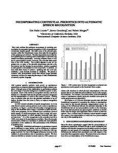
5. Performance Evaluation of Q-SCA In evaluating Q-SCA, it is important to quantify its run-time performance since it is built upon the COTS software layer containing the RT-CORBA ORB. To do so, we have completely implemented Q-SCA and constructed an Ethernet-based telephony application using Q-SCA components and interfaces. As introduced in Section 3.2, this application exchanges voice data over an Ethernet connection. We have conducted experiments to measure message propagation delay between application components. In this section, we report on our runtime performance evaluation of Q-SCA.
5.1. Experimental Setup Our Q-SCA was implemented using Linux v. 2.4.20 and the TAO [10] real-time ORB 1.3.1 on a hardware platform consisting of two embedded CPU boards. Each of them was equipped with a 1GHz Intel-compatible VIA processor and 256Mbytes DDR SDRAM. They were connected via 10Mbps Ethernet interfaces. One of the boards was also connected to the Internet via another 10Mbps Ethernet interface. The other has a soundcard with a microphone and a speaker connected. Although this configuration is not as complicated as actual wireless handsets, it has all the components required to measure the performance of Q-SCA without incurring various secondary effects that could otherwise be seen in a wireless environment. The Ethernet-based telephony application was constructed with two Q-SCA devices NetDevice and
Decompressor
Decipher
x86, Linux
x86, Linux 16
NetDevice
16
64
WCET: 4MFLOP
WCET: 5MFLOP
128
x86, Linux
x86, Linux Per 25ms From/to peer SDR device
WCET: 2MFLOP WCET: 2MFLOP
PCMAudio
128
64 64
Compressor
Cipher
128
In 300ms x86, Linux WCET: 4MFLOP
WCET: 1MFLOP
In 300ms Speaker Microphon Per 25ms
x86, Linux 16
16
WCET: 1MFLOP
64 WCET: 10MFLOP
128
Figure 9. Structure of internet telephony application and two Q-SCA Devices.
20 TCP/IP
18
CORBA
16 Percentage (%)
14 12 10 8 6 4 2 0 30
35
40
45
50
55
60
65
70
75
80
85
90
95
100 105 110 115
Latency (ms)
Figure 10. Distribution of latencies between Compressor and Cipher components. PCMAudio as shown in Figure 9. These devices abstract the Internet and the soundcard, respectively. The application maintains two dataflows simultaneously: a downstream dataflow from NetDevice to PCMAudio and an upstream dataflow in the opposite direction. For the upstream dataflow, audio samples captured by the PCMAudio component from the microphone are compressed and encrypted by Compressor and Cipher, respectively, and finally transmitted by NetDevice to the peer SDR device. Similarly, for the downstream dataflow, voice data received by NetDevice is decrypted and decompressed by Decipher and Decompressor, respectively, and finally played by PCMAudio. Each of the components comprising the application must be allocated with a specified amount of CPU resources for processing. For example, one invocation of Decipher takes 4 mega floating point operations in the worst case and consumes 16 tokens produced by the predecessor component, NetDevice, as seen in Figure 9. Both dataflows are expected to be initiated every 25ms as specified by the minimum execution period. Note that the Decipher and Cipher components need to be executed 4 times more often than other components. There are also QoS requirements to be met: both dataflows have a 300ms maximum latency requirement, meaning that the time taken for the total processing of any voice data should not exceed 300ms.
5.2. Performance Evaluation of Q-SCA In order to quantify the run-time performance overhead incurred by Q-SCA, we measured the delay incurred by transferring voice data between two application components deployed on two different nodes, and compared them with the case where Q-SCA is not used. If Q-SCA is not present, we assume that TCP/IP is directly used instead of the RT-CORBA ORB. Figure 10 shows the distribution of latencies incurred to transfer voice data from Compressor to Cipher using TCP/IP and the RT-CORBA ORB. The Compressor and Cipher components are selected among the others since
they are the components that our Q-SCA implementation deploys separately on different nodes. The average latency is about 70.5ms when we use Q-SCA, while it is 65.0ms when TCP/IP is used instead. Thus, the overhead incurred by Q-SCA is less than 10%. These results show that Q-SCA can provides applications with QoS guarantees with a relatively small overhead.
6. Conclusions and Future Work In this paper, we have proposed QoS-enabled SCA for SDR real-time waveform software and presented its complete implementation as an extension to our SNU-SCA. Q-SCA explicitly addresses the shortcomings of the current SCA specification. Even though SCA is the de facto standard middleware for SDR systems and widely accepted as a viable solution for reconfigurable, component-based distributed computing for adaptive wireless terminals and base stations, it lacks QoS capabilities in terms of both QoS specification and enforcement. The Q-SCA solves this problem using the PGM-based waveform application model and an extended SCA core framework. The contributions of our Q-SCA are threefold: (1) it provides a QoS descriptor that is backward compatible with SCA’s original domain profiles; (2) offers services for admission control and resource allocation that are used throughout the application instantiation process; and (3) introduces a mechanism to enforce the result of the resource allocation. In designing these mechanisms, we have focused only on the core framework of SCA since we could simply utilize the real-time and QoS capabilities of the COTS software including POSIX-compliant real-time operating systems and CORBA ORBs, as the SCA specification recommends. As a result, Q-SCA deals mostly with QoS specification and resource allocation during the application instantiation process. This renders Q-SCA clearly delineated from the original SCA and allows for easy and fast implementation. We have demonstrated its use via an Ethernet-based telephony application. This shows that Q-SCA can help developers effectively capture waveform applications and their QoS requirements and deploy them while satisfying the imposed constraints. Our measurements also show that its run-time performance penalty is relatively small. There exist several research directions along which Q-SCA can be extended. Currently, we are looking to extend its application domains by covering diverse QoS constraints other than real-time signal processing. Particularly, we are applying it to networked service robots where reactivity constraints co-exist with streambased multimedia constraints. They form a very attractive application domain for Q-SCA since they are extremely complex distributed real-time systems with stringent real-time constraints and a high degree of software reconfigurability requirements. Also, we are attempting to integrate with Q-SCA the QoS monitoring and adaptation capabilities of the COTS software layer in order to make it more adaptive to dynamically changing QoS requirements. Finally, it is also important to provide developers with a GUI-based XML tool that can automatically generate the extended domain profiles and skeleton code for waveform components. We are currently developing such tools.
References [1] Joint Tactical Radio Systems. “Software Communications Architecture Specification V2.2.” November 2002. [2] Joint Tactical Radio Systems. “Support and Rationale Document for the Software Communications Architecture Specification (v2.2).” December 2002 [3] Joint Tactical Radio Systems. “Software Communications Architecture Specification V2.2. API Supplements.” November 2002. [4] Object Management Group. “The Common Object Request Broker Architecture: Core Specification Revision 3.0.” December 2002. [5] J. Chapin and V. Bose. “The Vanu Software Radio System.” In Proceedings of Software Defined Radio Technical Conference, San Diego, November 2002. [6] J. Chapin, V. Lum, and S. Muir. “Experiences Implementing GSM in RDL.” IEEE Milcom 2001 (Military Communications), October 2001. [7] End-to-End Reconfigurability. URL: http://e2r.motlabs.com [8] K. Nahrstedt, D. Wichadakul, and D. Xu. “Distributed QoS Compilation and Run-time Instantiation.” In Proceedings of the Eighth IEEE/IFIP International Workshop on Quality of Service, pp. 198-207, June 2000. [9] B. Li and K. Nahrstedt,. “A Control-based Middleware Framework for Quality of Service Adaptations.” IEEE Journal of Selected Areas in Communications, Special Issue on Service Enabling Platforms, vol. 17, no. 19, pp. 1632-1650, September 1999. [10] F. Kuhns, D. D. Schmidt, et al. “The Design and Performance of a Real-Time Object Request Broker.” In Proceedings of IEEE Real-Time/Embedded Technology and Applications Symposium, May 2000. [11] J. Zinky, D. Bakken, and R. Schantz. “Architecture Support for Quality of Service for CORBA Objects.” Theory and Practice of Object Systems, vol. 3, no. 1, January 1997. [12] Institute for Electrical and Electronic Engineers. “Information Technology- Standardized Application Environment Profile- POSIX Realtime Application Support (AEP).” IEEE Std 1003.13, February 2000. [13] S. Kim, J. Masse, and S. Hong. “Dynamic Deployment of Software Defined Radio Components for Mobile Wireless Internet Applications.” In Proceedings of International Human.Society@Internet Conference (HSI), June 2003. [14] E.A. Lee and D.G. Messerschmitt. “Static Scheduling of Synchronous Data Flow Programs for Digital Signal Processing.” IEEE Transactions on Computers, C-36(1), pp. 24-35, January 1987. [15] E.A. Lee and T.M. Parks. “Dataflow Process Networks.” Proceedings of the IEEE, Vol.83, No.5, May, 1995. [16] S. Goddard and K. Jeffay. “Analyzing the Real-Time Properties of a U.S. Navy Signal Processing System.” International Journal of Reliability, Quality and Safety Engineering, vol.8, no.4, 2001. [17] Ojbect Management Group (OMG). “Real-Time CORBA Specification. Version 2.0.” formal/03-11-01, November 2003. [18] Jun Sun. "Fixed-Priority End-to-End Scheduling in Distributed Real-Time Systems." PhD thesis thesis, Department of Computer Science, University of Illinois at Urbana-Champaign. 1997. [19] Jun Sun, and Jane W.-S.Liu. "Synchronization Protocols in Distributed Real-Time Systems." In International Conference on Distributed Computing Systems. 1996.
[20] Krithi Ramamritham, John A. Stankovic, and Wei Zhao. "Dirstributed Scheduling of Tasks with Deadlines and Resource Requirements." IEEE Transactions on Computer Vol. 38, No. 8 (August 1989): pp. 1110-1123. [21] L. Sha, R. Rajkumar, and J. Lehoczky. "Real-Time Synchronization Protocol for Multiprocessors." In Proceedings of IEEE Real-Time Systems Symposium. pp. 259-269. New York, USA:Dec. 1998. [22] Christopher D. Gill, Ron K. Cytron, and Douglas C. Schmidt. "Multi-Paradigm Scheduling for Distributed Real-Time Embedded Computing." IEEE Proceedings Special Issue on Modeling and Design of Embedded Systems (January 2003) Vol. 91, No. 1. [23] L. DiPippo, V. F. Wolfe, L. Esibov, G. Cooper, R. Johnston, B. Thuraisingham, and J. Mauer. "Scheduling and Priority Mapping for Static Real-Time Middleware." Real-Time Systems (Kluwer Academic Publishers) Vol. 20, No. 2 (March 2001): pp. 155-182.
Jaesoo Lee received the BS degree in electrical engineering from Seoul National University, Korea, in 2001. He is now a PhD candidate at the School of Electrical Engineering and Computer Science of Seoul National University. He is also a member of Real-Time Operating Systems Laboratory at Seoul National University. His research interests include embedded/real-time operating systems, compiler optimization techniques, low-power computing, and component based software development. E-mail:
[email protected] Tel: +82-2-876-4065 Fax: +82-2-882-4656
Saehwa Kim received the BS and MS degrees in electrical engineering from Seoul National University, Korea, in 1997 and 2000, respectively. She is currently a PhD candidate at the School of Electrical Engineering and Computer Science of Seoul National University. She is also a member of Real-Time Operating Systems Laboratory at Seoul National University. Her current research interests include embedded software development methodology, real-time object-oriented modeling, embedded middleware, and real-time operating systems. E-mail:
[email protected] Tel: +82-2-880-8370 Fax: +82-2-882-4656
Jiyong Park was born in Daegu, Korea on November 26, 1979. He received the BS degree in electrical engineering from Seoul National University, Korea, in 2002. He is currently a PhD candidate at the School of Electrical Engineering and Computer Science of Seoul National University. He is also a member of Real-Time Operating Systems Laboratory at Seoul National University. His current research interests include customizable software development, aspect-oriented programming, and embedded real-time operating systems. E-mail:
[email protected] Tel: +82-2-876-4065 Fax: +82-2-882-4656
Seongsoo Hong received the BS and MS degrees in computer engineering from Seoul National University, Korea, in 1986 and 1988, respectively. He received the PhD degree in computer science from the University of Maryland, College Park, in 1994. He is currently an associate professor of School of Electrical Engineering and Computer Science at Seoul National University. His current research interests include embedded real-time systems design, real-time operating systems, embedded middleware, and software tools and environment for embedded real-time systems. He has served as a general co-chair of IEEE RTCSA 2006 and CASES 2006 and as a program committee co-chair of IEEE RTAS 2005, RTCSA 2003, IEEE ISORC 2002, and ACM LCTES 2001. He has served on numerous program committees including IEEE RTSS and ACM OOPSLA. He is currently a member of the IEEE and ACM. E-mail:
[email protected] Tel: +82-2-880-8357 Fax: +82-2-882-4656