QoS with TCP/IP and shared media LANs Heikki Kokkinen Nokia Research Center
[email protected] Tel. +358-9-4376-6651
Abstract The QoS over shared media LANs has three major elements: improving the current LANs for QoS, developing QoS aware LANs for future purposes, and utilizing the capabilities of QoS aware LANs optimally. Following the categorization, this paper discusses how TCP/IP is currently carried over the most popular shared media LAN, Ethernet, and how it is developed. An introduction to different LAN and packet based access networks is given. In the context of mapping the IP QoS to link layer, the work of IETF ISSLL group is referred. The shared media MAC protocols are discussed and an example of MAC protocol analysis is carried out by studying Slotted Aloha throughput and delay characteristics.
1
Introduction
The Quality of Service (QoS) is interpreted as a capability to provide the services to the customer in the way that he or she expects it. The expectations change fast as the information technology develops. So, in order to keep track on the QoS of a network also quantitative measures are used. These measures include at least throughput, packet loss, delay and delay variation. Transmission Control Protocol (TCP) and Internet Protocol (IP) are the most important layer 3 and 4 protocols in the data networks. The Local Area Networks (LAN) locate in the customer premises. The customer, organization or society typically shares computing and storage resources and accessories in that network. The local loop is the network connecting the local exchange, headend, point of presence or other operation point of an network operator to the customer premises. The difference between LAN and local loop may not remain clear in the future, at least from the link layer technology perspective. The networks which allow practically simultaneous access of several terminals on the same physical transmission medium are called shared. The access may be centrally controlled by a master or the control may be distributed. The QoS with TCP/IP in shared media LANs has three aspects: tuning the existing, not QoS aware link layers towards QoS, developing QoS capable link layer for new systems and signaling the QoS. The section 2 discusses
The Institute of Electrical and Electronics Engineers, Inc. (IEEE) 802 shared media LANs and how TCP/IP is carried over them. Tuning existing networks and the signaling are discussed in the section 3. The link layer QoS is mainly determined by the Medium (or Multiple) Access Control (MAC) protocol. The major categories of MAC protocols are listed in the section 4. An introduction to analysis of MAC protocols is given by using Slotted Aloha as an example in the section 5.
2
Shared media LANs
A good overview on the areas where shared media LANs are used, is the collection of IEEE 802 standards [6], which are collected in the Table 1. They include Collision Sense Multiple Access (CSMA) Collision Detect (CD), token bus, token ring, Distributed Queue Dual Bus (DQDB), wireless and cable television access methods. The various standards differ at the physical layer and MAC sublayer, but are compatible at the data link layer. The acceptance of these standards vary in the industry. For example combination of 802.2 and 802.3 defines a different frame format from the one which is used in the true Ethernet. 802.14 is practically not implemented, because of ETS300800 and Data Over Cable Service Interface Specification (DOCSIS). Additionally, European Telecommunication Standards Institute (ETSI) Hiperlan will compete with 802.11. Table 1: IEEE 802 standards and drafts [6] Number 802.1 802.2 802.3 802.4 802.5 802.6 802.7 802.8 802.9 802.10 802.11 802.12 802.14
IEEE standard or draft LAN/MAN Bridging & Management Logical Link Control CSMA/CD Access Method Token-Passing Bus Access Method Token Ring Access Method DQDB Access Method Broadband LAN Fiber Optics Integrated Services LAN/MAN Security Wireless Demand Priority Access Method Cable TV
a) 802.3 MAC
802.2 LLC
destination addr
source addr
length
DSAP AA
SSAP AA
6
6
2
1
1
802.2 SNAP cntl 03 1
org c
type
data
crc
3
2
38-1492
4
type 0800
IP datagram
b)
destination addr
source addr
type
data
crc
46-1500
4
type 0800
IP datagram
2
46-1500
IP header
TCP header
20
20
application data
c)
destination addr
source addr
ETPID
TCI, CFI=C
type
data
crc
6
6
2
2
2
46-1500
4
type 0800
IP datagram 46-1500
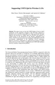
Figure 1: Encapsulation of TCP and IP according to a) RFC 1042, b) RFC 894 [13], and c) one of the extended Ethernet frames [7] -
2.1
TCP/IP over Ethernet
In the TCP/IP world, the encapsulation of IP datagrams is defined in RFC 894 [5] for Ethernet and in RFC 1042 [10] for IEEE 802 networks. It is required that every Internet host connected to 10 Mb/s Ethernet cable has to be able to transmit and receive according to RFC 894 and it has to be able to receive according to RFC 1042. The Figure 1 shows the encapsulation of TCP/IP packet in the Ethernet frame. The new fields in the extended Ethernet frame are Ethernet-encoded Tag Protocol Identifier (ETPID), Tag Control Information (TCI), and Canonical Format Identifier (CFI). The PID field varies depending on used Ethernet encapsulation i.e. with or without SNAP. The TCI field is two octets in length, and contains user_priority, CFI and Virtual LAN Identifier (VID). The user_priority is a three bit long field. It represents eight priority levels, 0 through 7.
3
IETF ISSLL
The Internet Engineering Task Force (IETF) Integrated Services over Specific Link Layers (ISSLL) Working Group tries to add more service levels than just the current IP best-effort within subnetwork technologies. The following items are specified for each network technology:
Service mappings define how the link layer provides integrated service management. - Setup protocol mappings defines how setup protocol such as RSVP is mapped onto the link layer technology. - Adaptation protocols utilize the native QoS capabilities of the link-layer technology. - Statements of non-applicability describe the limitations of the link layer for integrated services. The group tries to utilize the current link layer technology as well as possible, to follow the ongoing standardization on link layer protocols and to influence the development of the future link layers.
3.1
Framework [4]
There are several general requirements for the work: - Resource reservation - Admission control - Flow separation and scheduling - Policing/shaping - Soft state information is maintained soft state about reservations - Both centralized or distributed implementations are possible. - Scalability - Error recovery and fault tolerance - Co-existence with existing resource management
3.1.1 802 MAC capabilities IEEE 802.1D [8] defines a consistent way to carry user_priority value over a bridged network consisting of Ethernet, Token Ring, Demand Priority, FDDI or other MAC layer media using an extended frame format. It labels the packets according to the classes. The IEEE 802 specifications make no assumptions about how user_priority is to be used by end stations or by the network. Although IEEE 802.1D defines static priority queuing as the default mode of operation of switches that implement multiple queues, the user_priority is really a priority only in a loose sense since it depends on the number of traffic classes actually implemented by a switch. There is no explicit traffic class or user_priority field carried in Ethernet packets. This means that user_priority must be regenerated at a downstream receiver or switch according to some defaults or by parsing further into higher layer protocol fields in the packet. Alternatively, IEEE P802.1Q encapsulation [7] may be used which provides an explicit user_priority field on top of the basic MAC frame format.
3.1.2 Bandwidth Manager (5, 6, 7) The Bandwidth Manager (BM) is responsible for providing mechanisms for an application or higher layer protocol to request QoS from the network. The BM consists of Requester Module (RM), Bandwidth allocator (BA) and related communication protocols. The RM resides in every end station in the subnet. One of its functions is to provide an interface between applications or higher layer protocols such as RSVP, ST2, SNMP, etc. and the BM. The RM utilizes following parameters: desired class of service, the traffic descriptors contained in the TSpec, and a RSpec specifying the amount of resources to be reserved. The ISSLL group concentrates on the link layer capability to provide two classes of service. The Controlled Load service provides a loose guarantee, informally stated as "the same as best effort would be on an unloaded network", and the Guaranteed Service provides an upper bound on the transit delay of any packet. The BA is responsible for performing admission control and maintaining state about the allocation of resources in the subnet like bandwidth reservation, modification of an existing reservation, queries about resource availability. The communication between the end station and the BA takes place through the RM. The BA can be centralized or distributed. The BA is also responsible for labeling the flows. The centralized BA architecture is shown in the Figure 2.
BA Layer 2 App
App
RM
RM
Layer 2
Layer 2
Layer 2
RSVP Host / Router
Intermediate Bridge / Switch
Intermediate Bridge / Switch
Layer 2
RSVP Host / Router
Figure 2: Bandwidth Manager with centralized Bandwidth Allocator [4] The communication protocols are specified between the following entities: between the higher layer protocols and the RM; between the RM and the BA, between peer BAs.
3.1.3 Link layer support The bridges and switches have different capabilities of supporting QoS. The most basic bridge has a single queue per output port. Networks constructed from this kind of device cannot be expected to provide service guarantees of any kind because of the complete lack of traffic isolation. The next level bridges/switches are those, which conform to the more recently revised IEEE 802.1D specification. It will include support for queuing up to eight traffic classes separately. The level of traffic isolation provided is coarse because all flows corresponding to a particular traffic class are aggregated. A next step above these devices are bridges/switches which implement optional parts of the IEEE 802.1D specification such as mapping the received user_priority to some internal set of canonical values on a per-inputport basis. It may also support the mapping of these internal canonical values onto transmitted user_priority on a per-output-port basis. Other entirely optional features that some bridges/switches may support include classification of IntServ flows using fields in the network layer header, per-flow policing and/or reshaping which is essential for supporting Guaranteed Service, and more sophisticated scheduling algorithms such as variants of weighted fair queuing to limit the bandwidth consumed by a traffic class. The number of traffic classes supported and access methods of the technology under consideration will determine how many and what services may be supported. Native Token Ring/IEEE 802.5, for instance, supports eight priority levels, which may be mapped to one or more traffic classes. Ethernet/IEEE 802.3 has no support for signaling priorities within frames. However, the IEEE 802 standards committee has recently developed a new standard for bridges/switches related to multimedia traffic expediting and dynamic multicast filtering. A packet format for carrying a user_priority field on all IEEE 802 LAN media types is now defined. The standards allow for up to eight traffic classes on all
media. The user_priority bits carried in the frame are mapped to a particular traffic class within a bridge/switch. The user_priority is signaled on an endto-end basis, unless overridden by bridge/switch management.
3.2
SBM [15]
Subnet Bandwidth Manager (SBM) is a signaling protocol for RSVP-based admission control over IEEE 802-style networks. SBM provides a method for mapping an internet-level setup protocol such as RSVP onto IEEE 802- style networks. In particular, it describes the operation of RSVP-enabled hosts/routers and link layer devices (switches, bridges) to support reservation of LAN resources for RSVP-enabled data flows. A protocol entity called "Designated SBM" (DSBM) exists for each managed segment and is responsible for admission control over the resource reservation requests originating from the DSBM clients in that segment. The Figure 3 gives an example of SBM in a LAN sender. From IP
From RSVP
Address mapping
3.3
The DSBM processes the RSVP RESV message based on the bandwidth available.
Service mappings [12]
The service mappings the mapping of the traffic classes and the characterization parameters.
3.3.1 Learning the mapping In the aggregated flow model, each arriving flow is assigned to one of the available layer-2 classes and it traverses the 802 cloud in this class. The classes could be universally defined. The meanings of a set of classes; e.g. 1 = best effort, 2 = 100 ms peak delay target, 3 = 10 ms peak delay target, 4 = 1 ms peak delay target, etc. would be set. They could then be encoded directly in end stations, and the flow-to-class mappings computed directly in these devices. This universal definition approach would be simple to implement, but is too rigid to map the wide range of possible user requirements onto the limited number of available 802.1D classes. In a more flexible mapping clients ask the network which user_priority traffic class to use for a given traffic flow, as categorized by its flow-spec and layer-2 endpoints. The network provides a value back to the requester.
SBM signaling
SBM client
3.3.2 Characterization Parameters
802 header Local Admin. control Classifier
-
Packet scheduler
Data
Figure 3: SBM of a LAN sender [3] The basic DSBM-based admission control procedure has the following phases: - DSBM Initialization - DSBM Client Initialization - DSBM-based Admission Control The admission control is carried out in the following steps: - When a DSBM client sends or forwards a RSVP PATH message over an interface attached to a managed segment, it sends the PATH message to the segment's DSBM instead of sending it to the RSVP session destination address (as is done in conventional RSVP processing). - When an application on host A wishes to make a reservation for the RSVP session, host A follows the standard RSVP message processing rules and sends a RSVP RESV message to the previous hop L2/L3 address (the DSBMs address) obtained from the PHOP object(s) in the previously received PATH message.
The integrated service model requires that each network element that supports integrated services computes and makes available certain characterization parameters describing the behavior of the elements. - Ingress link - Egress links and their MTUs, framing overheads and minimum packet sizes - Available path bandwidth: updated hop-by-hop by any device along the path of the flow. - Minimum latency A network element supporting the Guaranteed Service must be able to determine the following parameters: - Constant delay bound through the device - Rate-proportional delay bound - Receive resources that would need to be associated with the flow e.g. buffering, bandwidth - Transmit resources that would need to be associated with the flow e.g. buffering, bandwidth, constantand rate-proportional delay bounds A network element implementing the Controlled Load service must be able to determine the following: - Receive resources that would need to be associated with the flow e.g. buffering - Transmit resources that would need to be associated with the flow e.g. buffering
4
MAC protocols
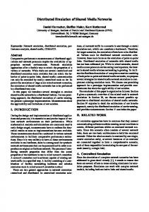
The link layer QoS characteristics are tied to the MAC protocol and to the physical layer framing structure. On the physical layer delay is caused for example due to propagation delay, error correction, interleaving, and large frames. All frame information related to functionalities, which require a transmission round trip, like acknowledgement, should occur fast enough. Also the segmentation of the large packets is an important feature. The MAC protocol controls how the terminals fill the physical frames. The MAC protocol can be in a centrally controlled point-to-multipoint or in a distributed multipoint-to-multipoint architecture. It is possible to obtain a deterministic delay by reserving capacity to the terminal on the transmission medium. Many of the recent MAC protocols include the reservation capabilities, but without defined QoS related signaling on the upper layers, their fancy features are useless. The general multiple access schemes are Time Division Multiple Access (TDMA), Frequency DMA (FDMA), and Code DMA (CDMA). In this context only TDMA approach is discussed but with little imagination the same principles can be applied to other access schemes, as well. The Figure 4 roughly shows the optimal application areas of different access types. The figure has intuitively been formed keeping the throughput – delay characteristics on mind. The best option for a particular case depends also on other requirements like delay tolerance, minimum throughput, stability, and complexity. The TDMA gives a fixed time slot for each terminal also when the terminal has nothing to send. TDMA is at its best when there is no burstiness in the traffic or when the number of users is relatively small. The opposite of TDMA is random access. Any user can send at anytime and collisions between terminals are resolved by waiting a random time before retransmission. Collision Sense Multiple Access (CSMA), Slotted Aloha, and splitting algorithms belong to this category. For a large number of users having large packets compared to time slot size, arriving in a bursty manner, the random reservation access is the most suitable access mode. The reservation request is transmitted using a small random access time slot and the channel capacity is reserved for the actual transmission. If the number of users is small, the best performance is achieved by allocating a small amount of TDMA capacity for reservation requests and reserving capacity for the actual transmission. TDMA reservation is a version of polling. In some applications you can also use random access to reserve a TDMA channel, but it could be considered to be a variation of random reservation. Token passing could also fit into random reservation or TDMA reservation depending on the method how the token is passed.
No. of users Random Random reservation
TDMA
TDMA reservation
Burstiness
Figure 4: Application areas of different access modes
5
Slotted Aloha analysis
The Slotted Aloha is one of the basic random access algorithms. It is selected as an example, because the analysis is simple. The analysis method can be applied to other protocols, as well. The analysis for finite number of terminals follows the references [9] and [11]. The channel is slotted; in this example we consider further that it is time slotted. The transmission of a packet takes T time units and at the same time T is the duration of a timeslot. Each terminal can have two states: thinking or backlogged. When a terminal has nothing to transmit it is in the thinking state. When a packet arrives to the terminal, it transmits the packet immediately. If the packet was received successfully the terminal enters the thinking state again, otherwise it goes to backlogged state. When in this state, the terminal transmits a packet in a slot with probability σ and it does not transmit with a probability 1 - σ.
5.1
Markov chain
Let the slots of the system be numbered sequentially k = 0, 1, … and let Ñ(k) denote the number of backlogged terminals at the beginning of the kth slot. Since statetransition of a terminal is independent of the activities in any previous slot, the process is a Markov chain. While the number of backlogged terminals cannot exceed the number of terminals M, this chain is finite. The transition diagram for the system is shown in Figure 5. Upward transition are possible between every state and all the higher numbered states, since a collision among any number of packets is possible. Downward transitions are possible only to the adjacent state since only one packet can be successfully transmitted in a slot. The diagram shows that all states communicate, so this Markov chain is ergodic, meaning that a steady-state distribution exists.
0
1
2
i
From 0 1 ... i-1 To i-1
5.3
Figure 5: State transitions of finite population Aloha [11]
5.2
Steady-state probabilities
Let πi be the steady-state probability of the system being
[~
]
in state i, that is π i = lim k →∞ Pr N ( k ) = i . Further let pij be the steady-state transition probability, i.e.,
[
]
~ ~ pij = lim k →∞ Pr N (k ) = j N (k − 1) = i . Finally
denote by P the matrix whose elements are pij and by π the row vector whose elements are i. From the above argumentation it follows that the steady-state probability vector is the solution to the finite set of linear equations. π = πP
∑π
i
=1
(1)
i
to which the existence of a unique solution is guaranteed. We must therefore construct the matrix P and derive the desired solution. Let us assume that the retransmission of every terminal is an independent geometric process. Then the probability that i out of the j backlogged terminals will schedule a retransmission in a given slot is binomially distributed: Pr[i backlogged terminals transmit in a slot | j in backlog]
j = ν i (1 − ν ) j −1 . i
(2)
In a similar manner, for the thinking terminals Pr[i thinking terminals transmit in a slot | j in backlog]
M − = i
[ [ [ [
M
To M ... i+2 i+1 From i+1
i
j < i -1 0 i −1 M −i j = i -1 iν (1 − ν ) (1 − σ ) 1 − iν (1 − ν ) i −1 (1 − σ ) M −i + (4) pij = (M - i)σ (1 - σ ) M -i -1 (i − ν ) i j=i M -i -1 1 − (1 − ν ) i j = i + 1 (M - i)σ (1 - σ ) M − i j > i +1 σ j −i (1 − σ ) M − j j − i
j i σ (1 − σ ) M − j −1 .
(3)
By studying the state transition diagram the following probabilities can be formulated:
]
]
] ][
]
Throughput and delay analysis
For a slot to be successful only a single transmission must take place within it. Either all backlogged terminals remain silent and a single new terminal transmits, or a single backlogged terminal transmits while no new packets arrive. Given that there are i backlogged terminals this can be stated as Psuc(i) = Pr[Successful slot | i terminals in backlog] =
(1 − υ ) i ( M − i )σ (1 − σ ) M −i −1
(5)
+ iν (1 − ν ) i −1 (1 − σ ) M −i If we do not distinguish new arrivals from the backlogged packets, ν = σ, we get
Psuc (i) = Mσ (1 − σ ) M −1 ,
(6)
which is independent of i. The throughput of Slotted Aloha becomes
S = E[Psuc (i )] = Mσ (1 − σ ) M −1 .
(7)
When the system is in state i there are M – i thinking terminals each generating packets in every slot with probability σ. Thus, the average rate of new packet generation when in state i is (M – i)σ. Using this we obtain
~ S = E[( M − i )σ ] = (M − N )σ ,
(8) where Ñ is the average number of backlogged terminals. Denote by b the average rate at which packets join the backlog. According to Little's formula, the average amount of time spent in the backlog is the ratio of the average number of backlogged terminals to the average rate of joining or Ñ / b. Some of the packets go through on the first try and some of the packets must go through the backlogged state. This is reflected in the average delay of the protocol:
~ bN ~ S −b D= ⋅ 1 + + 1 S Sb . ~ 1 M N = 1+ = 1− + S σ S
(9)
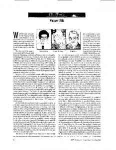
1 − (1 − σ ) M −1 ~ . D =1+ σ (1 − σ ) M −1
(10)
For the special case ν = σ, we get
The Figure 6 shows the delay behavior as a function of throughput.
Figure 6: Slotted Aloha delay as a function of throughput
6
Conclusion
The majority of existing shared media LANs do not provide QoS. There is development going on to enhance the capabilities into QoS aware direction. The IEEE has revised the 802 specifications for QoS support. In order to utilize those capabilities the products have to support those features. The shared media LANs under development include some capabilities on the link and MAC layer. In that case a mapping of QoS on IP level to link layer needs to be specified. IETF ISSLL group is working on the area of supporting RSVP over IEEE 802 networks. The work is on IETF draft level. The IP QoS signaling with non IEEE 802 link layers is a big question mark. In the recently developed link layers, there are three payload framing strategies: Ethernet bridging brings the Ethernet problems with it, ATM support may be or may not be a practical solution for QoS signaling, from-the-scratch link layer has the highest potential, but it also requires most specification. For that, the signaling of QoS is a totally open issue. A trivial solution to improve the QoS of an arbitrary traffic load is just to increase the link layer bandwidth.
7
References
[1] Braden, B. & Zhang, L. & Berson, S. & Herzog, S. & Jamin, S. Resource Reservation Protocol (RSVP) -Version 1 Functional Specification, RFC 2205, September 1997. [2] Braden, R. & Clark, D. & Shenker, S. Integrated Services in the Internet Architecture: An Overview, RFC 1633, June 1994. [3] Ferguson, Paul & Huston, Geoff. Quality of Service. John Wiley & Sons, Inc. New York, NY, 1998. ISBN 0-471-24358-2. [4] Ghanwani, Anoop & Pace, Wayne J. & Srinivasan, Vijay & Smith, Andrew & Seaman, Mick. A framework for providing integrated services over shared and swithced IEEE 802 LAN technologies. May 1998. draft-ietf-issll-is802-framework-05.txt.
[5] Hornig, Charles. A Standard for the Transmission of IP Datagrams over Ethernet Networks, April 1984, RFC 894. [6] http://standards.ieee.org/catalog [7] IEEE Standards for Local and Metropolitan Area Networks: Draft Standard for Virtual Bridged Local Area Networks, P802.1Q/D11, July 30, 1998. [8] IEEE Standards for Local and Metropolitan Area Networks: Media Access Control (MAC) bridges, P802.1D/D17, May 25, 1998. [9] Kleinrock, L. & Lam, S. S. Packet switching in a multiaccess broadcast channel: Performance evaluation. IEEE Transactions on communications, Vol. 23, No. 4, 1975. Pp 410-423. [10] Postel, J. & Reynolds, J. A Standard for the Transmission of IP Datagrams over IEEE 802 Networks, February 1988, RFC 1042. [11] Rom, Raphael & Sidi, Moshe. Multiple access protocols. Performance and analysis. SpringerVerlag, New York, NY, 1990. ISBN 0-387-97253-6. [12] Seaman, M. & Smith, A. & Crawley, E. & Wroclawski, J. Integrated Service Mappings on IEEE 802 Networks. November 1998. draft-ietfissll-is802-svc-mapping-03.txt. [13] Stevens, Richard W. TCP/IP Illustrated, Volume 1. The protocols. Addison-Wesley, Reading, MA, 1994. ISBN 0-201-63346-9. [14] Wroclawski, J. The Use of RSVP with IETF Integrated Services, RFC 2210, September 1997. [15] Yavatkar, Raj & Hoffman, Don & Bernet, Yoram & Baker, Fred & Speer, Michael. SBM (Subnet Bandwidth Manager). November 1998. draft-ietfissll-is802-sbm-07.txt.