AbstractâThis paper proposes a new family of random modulation techniques for three-phase power converters which operate with a fixed switching frequency.
IEEE TRANSACTIONS ON POWER ELECTRONICS, VOL. 15, NO. 4, JULY 2000
753
Random Modulation Techniques with Fixed Switching Frequency for Three-Phase Power Converters Michael M. Bech, Member, IEEE, Frede Blaabjerg, Senior Member, IEEE, and John K. Pedersen, Member, IEEE
Abstract—This paper proposes a new family of random modulation techniques for three-phase power converters which operate with a fixed switching frequency. The techniques are based on adjusting the duration of the zero-vectors or adjusting the three pulse positions in a switching period. Three methods are selected for experimental tests because they preserve the fixed switching frequency known from standard PWM techniques. The new methods are also compared with random switching frequency modulation and with fixed switching frequency modulation. Voltage, current and acoustic noise spectra are used for comparison and it is concluded that two of the techniques are especially useful at lower fundamental frequencies. The techniques can substitute classic random modulation techniques with variable switching frequency in some applications. Index Terms—AC-drives, acoustic noise, PWM modulation, random modulation.
I. INTRODUCTION
A
DJUSTABLE speed drives have reached a state where they have became a mature component in many industrial applications [1]. The main reasons are their capabilities of energy savings, improved automation performance, and also the cost is steadily decreasing. Many technologies in adjustable speed drives are still being improved, among them sensorless control, manufacturing techniques, power converter design, and also the pulse-width modulation (PWM) itself. The last is important for the drive performance in respect to current harmonics, torque ripple and also acoustic noise emitted from e.g. an induction motor [2], [3]. Different approaches are used in PWM including switching with lower frequency (gives acoustic noise but also low losses) [4], switching with high kHz, which increases the losses in the inverter frequency but eliminates the noise problem) [5], [6] or using a random switching frequency [7]–[9]. The latter method is interesting because the average switching frequency can be kept low as can the acoustic annoyance. Many random modulation strategies have been discussed in the past. One approach uses the space vector modulation technique extended with a variable switching frequency operation, which effectively reduces the acoustic annoyance, but problems arise in the control system because then a variable sampling frequency in the controller are needed if the modulator and the conManuscript received April 28, 1999; revised March 23, 2000. Recommended by Associate Editor, F. Z. Peng. The authors are with the Institute of Energy Technology, Aalborg University, Aalborg East DK-9220, Denmark. Publisher Item Identifier S 0885-8993(00)05579-4.
troller shall operate in synchronism [9], [10]. Another method shifts randomly between lagging- and leading-edge modulation [11], which effectively gives a random modulation but problems appear in the sampling of the currents without using any anti-aliasing filters. A third approach is to select the switching frequency randomly among a few pre-determined frequencies and in that way limit the problem of randomization in the control loop [15], but in general it can be difficult to select the different switching frequencies [12] in real applications. This paper proposes a new family of random modulation techniques operating at a fixed switching frequency, but the pulses are randomly positioned within the switching period. Included is also a method that randomly changes the duration of the zerovectors (111) and (000). The methods are applicable to power converters without any neutral connection. This paper first discusses methods to inject random properties into a modulator running at fixed switching frequency. Also, an analysis of the current ripple is presented. Next, methods to implement the proposals are presented and the methods are implemented in a test setup. They are also compared with classical random and fixed switching frequency methods. Finally, a table of comparison is given showing the advantages and the disadvantages of the tested modulators. II. RANDOM PWM WITH FIXED SWITCHING FREQUENCY All the proposed techniques have the common property that the switching frequency is constant. As stated above this may ease the implementation of digital controllers, which often are synchronized to the switchings of the inverter, which in turn is controlled by the PWM unit. Having excluded the switching frequency as the parameter to randomize, it seems that the pulse position is the only quantity which can be randomized while still keeping the average voltage produced by the inverter fully controllable within each switching interval. However, as discussed shortly this is not the case. The fundamental idea behind random pulse position techniques is that the mean voltage measured across one switching interval is independent of the position of the pulse. This degree-of-freedom may be utilized in various ways, and from a theoretical point of view, the only constraint is that a pulse must not extend beyond the boundaries of the switching interval in question. That constraint may be met in a number of different ways, but the literature dealing with random pulse position has focussed almost exclusively on one simple variant, namely the so-called lead-lag random pulse position technique originating
0885–8993/00$10.00 © 2000 IEEE
754
IEEE TRANSACTIONS ON POWER ELECTRONICS, VOL. 15, NO. 4, JULY 2000
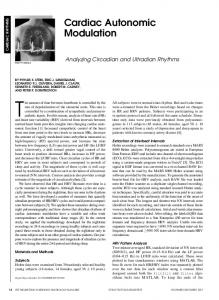
Fig. 1. Different fixed switching frequency modulation schemes. (a) Random lead-lag modulation (RLL). (b) Random center displacement (RCD). (c) Random zero vector distribution (RZD). (d) Random switching frequency (RS).
from [11]. Sketches of the investigated methods are shown in Fig. 1 including the method of [11]. and indicate the PWM In the figure, the symbols , switching functions for the three phases and is the switching period. Below, these methods are commented: Random Lead-Lag Modulation (RLL) [11]: The pulse position is either commencing at the beginning of the switching interval (leading-edge modulation) or its tailing edge is aligned with the end of the interval (lagging-edge modulation). The choice between leading- and lagging edge modulation is controlled by a random number generator. Random Displacement of the Pulse Center (RCD): Fig. 1(b) shows a method where the pulses are mutually center-aligned as
in space vector modulation (SVM) [2], but the common pulse center is displaced by the amount from the middle of the period. The parameter is varied randomly within a band limited by the maximum duty cycle. Random Distribution of the Zero Voltage Vector (RZD) [13], [14]: In a three-phase, three-wire system the duration of the zero voltage vector does not alter the phase voltages. This fact is utilized in the random distribution of the zero voltage vector, where the proportion between the time durations for the two zero-vector states 111 and 000 is randomized in a switching cycle [see Fig. 1(c)]. All pulses are center-aligned as in standard SVM. Random Switching Frequency (RS) [12]: For convenience, a classic random modulation structure is also included in
BECH et al.: RANDOM MODULATION TECHNIQUES WITH FIXED SWITCHING FREQUENCY
Fig. 1(d), where the switching period is randomly varied etc.) within a limited interval. ( The methods RLL, RCD and RZD are all operating with fixed switching frequency. Two different limitations in respect to randomization exist in RCD and RZD. In the RCD the maximum duty cycle of , or gives the maximum possible displacement of the pulses. This means that at high modulation indices the available displacement interval will be reduced. In the RZD, the durations of the two zero-vectors (000 and 111) are not equal like in [2], but randomly distributed. However, the duration of the zero-vectors limits the maximum pulse change and at high modulation indices the zero-vectors are short leaving less room for randomization.
755
where the ripple components are and (the bars over the symbols are used to distinguish average values from ripple components). and Definitions of the average value of the ripple currents within the intervals and , respectively becomes useful later, i.e., (4) A similar definition holds for . Also, the average current ripple defined over the whole switching interval is used later: . Ideally, these currents should all equal zero. B. Current Ripple for SVM
III. ANALYSIS OF CURRENT RIPPLE A. Calculation of Current Ripple Trajectories It may be tempting to state that since all the random PWM methods presented above produce the same average voltage space-vector, these methods do also cause the same average current to flow into the load. However, in this section it is shown that the fundamental component of the current is distorted by the modulation process for some of the modulators described above. To facilitate the analysis the concept of space-vector current ripple is used; this technique has been applied in numerous publications, notably in [16], [17] and many companion papers. The analysis assumes that the following complex-valued differential equation describes the relationship between the instantaneous and the resulting current inverter voltage (1) where is the electromotive force (emf) of the load, and and are the equivalent inductance and the resistance of the load, respectively. If the duration of the switching interval is short the impact of may be igcompared to the time constant nored. In this case the current trajectory may be obtained by the integration for
(2)
the voltages on the right-hand side During the interval may be divided into two parts: (a) the ripple components that change during the interval and (b) the mean values, which are considered constants during the switching interval. The latter part is responsible for the average behavior of the inverter-load cascade. The ripple components relates to the switching operation of the inverter i.e., in the ideal case the ripple components vanish. It is usually assumed that the back-emf voltage is unaffected by the nonfundamental voltage components in the inverter voltage . Then the behavior of the ripple voltage and current follows as (3)
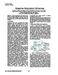
and for a It is instructive to calculate the trajectory well-known modulation technique before extending the analysis to the random PWM methods. Using the SVM technique as an example, sample results are shown in Fig. 2(d). The refis determined by the duty ratios of the active erenc voltage for and for . As shown in vectors: Fig. 2(d), the zero vectors are distributed uniformly as dictated etc. by the SVM technique i.e., A number of observations can be made. is con1) The trajectory of the instantaneous value of strained to move in directions parallel to one of the , ) or ( ). voltage vectors follows two rotational-symmetrical triangular paths 2) having one common side in the direction of the reference voltage vector . The first triangle is spanned by . , has completed the first triangle; also, 3) At . For the second . triangle is traversed ending in the origin again for 4) It follows from Fig. 2(d) that the mean value of phase a ripple voltage and current both evaluate to zero averaged across the switching interval. Furthermore, for the average ripple currents defined by (4), the figure shows . that In brief, the results show that the current caused by the imby the pulse-width modulation process perfect synthesis of does not influence the change of the average load current. At a first glance, this step-by-step procedure leading to this obvious conclusion seems superfluous because the net change of the average current can be determined by knowing the mean voltage , the back emf , the total inductance and the duration of the application of the mean voltage vector. A very tempting conclusion to draw from this example is to state that is independent of the change of the average current during the ripple component caused by the pulse-width modulation. As demonstrated shortly, however, this statement is not correct for all modulators. C. Current Ripple for Fixed-Frequency Random PWM Techniques The current ripple trajectories have been calculated for the different fixed-frequency randomization methods shown in Fig. 1. In all cases, the modulators produce active vectors of
756
IEEE TRANSACTIONS ON POWER ELECTRONICS, VOL. 15, NO. 4, JULY 2000
Fig. 2. Illustration of current quality. In all cases, the reference voltage is the same (d = 0:2 and d = 0:5). Each subfigure (a) RLL, (b) RCD, (c) RZV, and (d) RS shows the inverter gating pulses, the phase a is ripple voltage and current components and the current trajectory in the complex plane.
duration identical to the SVM example in Fig. 2(d), i.e. exactly is generated by the inverter the same average voltage vector irrespective of the randomization method. The results in Fig. 2(c) have been obtained for the random zero-vector distribution technique. In general, the trajectory of is still comprised by two triangles, but the path does not exhibit the same degree of symmetry as in the SVM case. The triangles slide along the direction of ; the exact amount of
the displacement depends on how the total zero-vector duration is divided among the two zero-vectors and . Also, the and , the ripple figure shows that at the time instants as in the SVM case. current is The inter-sample behaviors are, however, different. It is noteworthy to observe that in case of in Fig. 2(c) the av, but in Fig. 2(b) erage ripple current vectors fulfill for the RCD technique. This fact implies that in
BECH et al.: RANDOM MODULATION TECHNIQUES WITH FIXED SWITCHING FREQUENCY
Fig. 3.
757
Implementation of random modulation with center displacement and random zero vector distribution.
this case the ripple current (caused by ) affects the value of into the average current: the separation of the actual voltage and ripple components does not unconditionally average imply that average current can be determined without paying attention to . (However, the converse is true: does not contribute to ). Summing up, for the center-displaced method in Fig. 2(b) it may be observed that the instantaneous ripple currents pass but still the total mean ripple through zero at does not evaluate to zero. current The lead-lag type of modulation produces the results shown in Fig. 2(a). Due to the poor locations of the zero-state vectors, the current-ripple vector describes an area much larger than the other methods. The highly asymmetric pulse pattern causes a large average current ripple vector compared to the other methods as well as large peak to peak ripple currents. IV. IMPLEMENTATION ASPECTS In order to implement the random modulation strategies it is necessary with a flexible PWM unit. Fig. 3 shows how the two new modulation strategies can be implemented. The reference for the modulator is the average voltage vector defined by its magnitude U and its position . This is used in a standard space vector modulator [2] implemented as a look-up table. The output ). Those are used to calculate is three duty-ratios ( by comparison of the maximum possible displacement their magnitudes. The actual displacement is calculated by ranand depending on whether RCD or RZD is domizing of used, two compare levels (P1, P2) in a timer are calculated and used for . Correspondingly are P3–P6 also calculated for the as shown in two other phases. If RCD is used, equal to Fig. 1(b) and if RZD is used, is equal to the duration of the zero vector (000) . Lead-lag modulation is implemented by using only one compare level P1 for each phase. Measurements are done on the setup shown in Fig. 4. The inverter is a three-phase standard frequency converter with an input phase-phase voltage of 400 V, but without the control board. The rated output voltage is 400 V and the rated output current is 8 A. The inverter is fed from a three-phase diodebridge rectifier with a smoothing LC-filter in the dc-link which gives an average dc-link voltage of 540 V. The induction motor is a four-pole 2.2 kW machine, 400 V/ 4.9 A. The main param; eters of the induction motor are: stator resistance ; stator leakage inductance rotor resistance mH; rotor leakage inductance mH and the magnemH. tizing inductance The control is implemented in a combined DSP (Analog Devices ADSP-21 062 SHARC) and microcontroller (Siemens SAB C167) system. The DSP handles all calculations in
Fig. 4. Experimental setup.
real-time using floating-point arithmetic, including the task of generating random numbers to the random PWM. The microcontroller generates the switching functions to the inverter by means of built-in Capture-Compare (CAPCOM) timers that have a resolution of 400 ns. A Brüel & Kjaer Pulse Multi Analyzer system is used as Dynamic Signal Analyzer. The noise bandwidth for the analyzer is 12 Hz. A microphone measures the acoustic noise from the induction motor and it is placed in a distance of 20 cm from the induction motor. Voltage and currents are sensed using Tektronix probes and amplifiers. All measurements are represented in dB and as peak-values. Following base-lines are used: Sound Pressure Level Voltage (line-to-line) Current (phase)
dB dB dB
Pa V A
V. TEST RESULTS Experiments are done for the three random modulation techniques with fixed switching frequency. Included are also results for the classic random switching frequency technique with kHz, maximum the minimum switching frequency kHz and for fixed switching freswitching frequency quency operation at 5 kHz. Power spectra for the current, the line-to-line voltage and the acoustic noise are measured at two fundamental frequencies, 5 Hz and 40 Hz. At those two fundamental frequencies the modulation index are 0.13 and 0.83 respectively. The power spectral density (PSD) is used as a result because of the nondeterministic nature of the signals. The induction motor runs unloaded. The test results are shown in Figs. 5 and 6. Comparing the voltage spectra in Fig. 5 distinct harmonic voltage components appear in the case of fixed switching and random lead-lag, while the power spectra is much more smooth
758
IEEE TRANSACTIONS ON POWER ELECTRONICS, VOL. 15, NO. 4, JULY 2000
Fig. 5. Measured power spectral density (PSD) for the phase current (left column), line-to-line voltage (middle column) and acoustic noise (right column) for 5 Hz fundamental and with a modulatio index of 0.13. The motor is unloaded. (a)–(c) Fixed frqeuency. (d)–(f) Random lead-lag. (g)–(i) Random center displacement (j)–(l). Random zero vector distribution. (m)–(o) Random switching frequency.
for the other three methods. The most smooth power spectra is random zero vector distribution and from a subjective point of view the acoustical noise from the induction motor is the least annoying. At higher fundamental frequency (Fig. 6) more pronounced harmonics are present in all measured spectra except
for the random switching frequency technique. The main reason is that the freedom to randomize the PWM-signals are limited in the random center displacement and the random zero vector distribution at higher fundamental frequencies, because the value approaches zero. of
BECH et al.: RANDOM MODULATION TECHNIQUES WITH FIXED SWITCHING FREQUENCY
759
Fig. 6. Measured power spectral density (PSD) for the phase current (left column), line-to-line voltage (middle column) and acoustic noise (right column) for 40 Hz fundamental and with a modulatio index of 0.83. The motor is unloaded. (a)–(c) Fixed frequency. (d)–(f) Random lead-lag. (g)–(i) Random center displacement. (j)–(l) Random zero vector distribution. (m)–(o) Random switching frequency.
The same tendency is seen for the current spectra. The acoustic spectra show the broadest spectra in RCD, RZD, and RS especially at low modulation index. At higher modulation index low frequency noise can be seen which originates from the fan. RS has the broadest spectrum in this case. The advantages and disadvantages for the modulation principles are summarized in Table I.
A noise-free current sampling is attractive in closed-loop operation and a standard industrial solution is to sample when no switching interests happen in the inverter i.e. in the beginning, in the end, or in the center of the switching interval. Otherwise filters have to be introduced and it may reduce the possible bandwidth. Also, it is important that the sampled current is a proper measure for the average current during one
760
IEEE TRANSACTIONS ON POWER ELECTRONICS, VOL. 15, NO. 4, JULY 2000
TABLE I COMPARISON OF DIFFERENT RANDOM MODULATION TECHNIQUES
switching interval. This is done without problems in fixed switching operation and also for RS and RZD, but the other methods do not comply well with the sampling. Incorporating the strategies in digital control systems are easy because of fixed switching frequency operation and synchronizing is easily obtained. When random switching frequency is used the control loops have to be modified [15]. In the RLL strategy a correct current sampling is very difficult to achieve because of the asymmetric modulation. Space vector modulation at low modulation index with fixed switching frequency assures a low current ripple. Using RS, RZD or RCD will increase the peak-to-peak ripple, but not as much as the poor-performing RLL technique. This relates to the results shown in Fig. 2. The acoustic noise are most pleasant (or rather: less annoying) for RCD, RZD and RS both at low and high modulation index. However, the limited freedom for pulse placement in RCD and RZD will not reduce the noise as much at high modulation index compared to low modulation index. However, at high modulation index other noise sources are present, which tend to dominate, like fan noise. Common for RLL and fixed switching frequency operation is that they cause more annoying noise because of the distinct tones. All methods need extra calculations for doing the randomization compared to switched frequency operation. Fortunately, RCD, RZD and RLL need only additions/subtractions which limits the total calculation overhead. In RS the calculations may need divisions/multiplications [9] which adds extra calculation overhead.
VI. CONCLUSION A new family of random modulation methods for three-phase power converters, operating at a fixed switching frequency is proposed, discussed, implemented and compared. Two different methods that randomize the pulse width or the pulse position have been shown to have the same performance with respect to acoustic noise abortement as random switching frequency at low fundamental while the random switching frequency method has the best performance at higher fundamental frequencies. However, in many applications the most annoying inverter-fed acoustical noise is generated at low fundamental and therefore these new solutions may be attractive for HVAC-applications. At higher speed levels aerodynamic noise from the load and the fan tend to be the dominating acoustic noise sources. REFERENCES [1] B. K. Bose, Power Electronics and Variable Frequency Drives—Technology and Applications. New York: IEEE Press, 1996. [2] J. K. Pedersen and P. Thoegersen, “Stator flux oriented asynchronous vector modulation for AC-drives,” in Proc. PESC’90, 1990, pp. 641–648. [3] V. G. Törrök, “New optimum on-line modulation for PWM inverters,” in Proc. IFAC Symp., Lausanne, Switzerland, 1983, pp. 247–254. [4] J. Holtz and B. Beyer, “Optimal pulsewidth modulation for AC servos and low-cost industrial drives,” in Proc. Conf. Rec. 1992 IEEE Ind. Applicat. Soc. Annu. Meeting, 1992, pp. 1010–1017. [5] S. Legowski and A. M. Trzynadlowski, “Hypersonic MOSFET-based power inverter with random pulse width modulation,” in Proc. Conf. Rec. 1989 IEEE Ind. Applicat. Soc. Annu. Meeting, 1989, pp. 901–903. [6] A. M. Trzynadlowski, F. Blaabjerg, J. K. Pedersen, R. L. Kirlin, and S. Legowski, “Random pulse width modulation techniques for converter fed drive systems—A review,” IEEE Trans. Ind. Applicat., vol. 30, pp. 1166–1175, Sept./Oct. 1994.
BECH et al.: RANDOM MODULATION TECHNIQUES WITH FIXED SWITCHING FREQUENCY
[7] A. M. Trzynadlowski, S. Legowski, and R. L. Kirlin, “Random pulse width modulation technique for voltage-controlled power inverters,” in Proc. Conf. Rec. 1987 IEEE Ind. Applicat. Soc. Ann. Meeting, 1987, pp. 863–868. [8] T. G. Habetler and D. M. Divan, “Acoustic noise reduction in sinusoidal PWM drives using a randomly modulated carrier,” IEEE Trans. Power Electron., vol. 6, pp. 356–363, July 1991. [9] J. K. Pedersen and F. Blaabjerg, “Implementation and test of a digital quasirandom modulated SFAVM PWM in a high performance drive system,” in Proc. IEEE-IECON ’92, 1992, pp. 265–270. [10] J. T. Boys and P. G. Handley, “Spread spectrum switching: Low noise modulation technique for PWM inverter drives,” Inst. Electron. Eng.—Proc. Part B, vol. 139, no. 3, pp. 252–260, May 1992. [11] S. Legowski and A. M. Trzynadlowski, “Advanced random pulse width technique for voltage-controlled inverter drive systems,” in Proc. 6th Ann. IEEE Appl. Power Electron. Conf., 1991, pp. 100–106. [12] F. Blaabjerg, J. K. Pedersen, L. Oestergaard, R. L. Kirlin, A. M. Trzynadlowski, and S. Legowski, “Optimized and nonoptimized random modulation techniques for VSI drives,” EPE J., vol. 6, no. 2, pp. 46–53, 1996. [13] V. Blasko, “Hybrid pulse width modulation method and apparatus,” U.S. Patent 5 706 186, Sept. 23, 1996. , “Analysis of a hybrid PWM based on modified space-vector and [14] triangle-comparison methods,” IEEE Trans. Ind. Applicat., vol. 33, pp. 756–764, May/June 1997. [15] M. M. Bech, J. K. Pedersen, and F. Blaabjerg, “Field-oriented control of an induction motor using random pulse width modulator,” in Proc. 2000 Appl. Power Electron. Conf., vol. 2, 2000, pp. 924–931. [16] H. W. Van Der Broeck, H. C. Skudelny, and G. V. Stanke, “Analysis and realization of a pulsewidth modulator based on voltage space vectors,” IEEE Trans. Ind. Applicat., vol. 24, pp. 142–150, Jan./Feb. 1988. [17] J. W. Kolar, H. Ertl, and F. C. Zach, “Minimizing the current harmonics RMS value of three-phase PWM converter systems by optimal and suboptimal transition between continuous and discontinuous modulation,” in Proc. 1991 IEEE Power Electron. Specialists Conf., vol. 1, 1991, pp. 372–381.
Michael M. Bech (S’95–M’00) was born in Denmark in 1971. He received the M.S. degree in electrical engineering and the Ph.D. degree from Aalborg University, Denmark, in 1995 and 1998, respectively. Since 1995, he has been with the Department of Electrical Engineering Conversion, Aalborg University, first as a Ph.D. candidate and currently as an Assistant Professor. For a three months in 1998, he was a Visiting Researcher with the University of Nevada, Reno. His main research area is analysis of random pulse-width modulation techniques for static power converters. Other areas of interest include power electronic converters and their applications. Dr. Bech is a Member of the IEEE Industry Applications Society, the IEEE Power Electronics Society, and the IEEE Industrial Electronics Society.
761
Frede Blaabjerg (S’86–M’91–SM’97) was born in Erslev, Denmark, on May 6, 1963. He received the Msc.E.E. and Ph.D. degrees from Aalborg University, Denmark, in 1987 and 1995, respectively. He was with ABB-Scandia, Randers, from 1987 to 1988. He became an Assistant Professor in 1992 at Aalborg University, in 1996, he became Associate Professor, and in 1998, a Full Professor in power electronics and drives. His research areas are in power electronics, static power converters, ac drives, switched reluctance drives, modeling, characterization of power semiconductor devices, and simulation. He is involved in more than ten research projects with the industry. Dr. Blaabjerg received the 1995 Angelos Award for his contribution in modulation technique and control of electric drives, and an Annual Teacher prize at Aalborg University, also in 1995. In 1998, he received the Outstanding Young Power Electronics Engineer Award from the IEEE Power Electronics Society and an IEEE TRANSACTIONS ON POWER ELECTRONICS Prize paper award for best paper published in 1997. Finally, he received two prize paper awards at the IEEE Industry Applications Annual Meeting in 1998. He is a member of the European Power Electronics and Drives Association and the IEEE Industry Applications Society Industrial Drives Committee. He is also a member of the Industry Power Converter Committee and the Power Electronics Devices and Components committee in the IEEE Industry Application Society and associated editor of Elteknik. He is the paper review chairman of the Industrial Power Converter Committee in the IEEE Industry Application Society. He serves as a member of the Danish Technical Research Council and a member of the board of the Danish Space Research Institute.
John K. Pedersen (M’91) was born in Holstebro, Denmark, on September 2, 1959. He received the Bsc.E.E. degree from Aalborg University, Denmark. He was with the Institute of Energy Technology, Aalborg University, as a Teaching Assistant, from 1983 to 1984, as an Assistant Professor from 1984 to 1989, and as an Associate Professor since 1989. He is the head of the Institute of Energy Technology. His research areas are in power electronics, power converter, and electrical drive systems, including modeling, simulation, and design with focus on optimized efficiency. Mr. Pedersen received the 1992 Angelos Award for his contribution in the control of induction machines. In 1998 he received an IEEE TRANSACTIONS ON POWER ELECTRONICS Prize paper award for best paper published in 1997.


![Digital modulation techniques [Book Review] - IEEE ...](https://m.moam.info/img/260x300/digital-modulation-techniques-book-review-ieee-_59acad671723ddbac5e50c76.jpg)


