an IP-based wireless network consisting of both wired and wire- less links is addressed. ... the best video quality. Simulation results illustrate the advantage ... these two types of packet loss is to use FEC at both the transport and the link layer.
➠
➡ RATE-DISTORTION OPTIMIZED PRODUCT CODE FORWARD ERROR CORRECTION FOR VIDEO TRANSMISSION OVER IP-BASED WIRELESS NETWORKS Fan Zhai, Yiftach Eisenberg, Thrasyvoulos N. Pappas, Randall Berry, and Aggelos K. Katsaggelos Department of Electrical and Computer Engineering Northwestern University, Evanston, IL 60208, USA E-mail: {fzhai, yeisenbe, pappas, rberry, aggk}@ece.northwestern.edu ABSTRACT The problem of encoding and transmitting a video sequence over an IP-based wireless network consisting of both wired and wireless links is addressed. To combat the different types of packet loss in the heterogeneous network, the use of a product code forward error correction (FEC) scheme capable of providing unequal error protection is considered. At the transport layer, Reed-Solomon (RS) coding is used to provide inter-packet protection. In addition, rate-compatible punctured convolutional (RCPC) coding is used at the link layer to provide unequal intra-packet protection. Optimal bit allocation is performed in a rate-distortion optimized joint source-channel coding and power allocation framework to achieve the best video quality. Simulation results illustrate the advantage of the proposed product code FEC scheme over previously studied approaches. 1. INTRODUCTION When transmitting multimedia over an unreliable channel, several methods can be used to provide error control, including error resilient source coding, channel coding, transmitter adaptation, and error concealment. Channel coding is typically in the form of forward error correction (FEC) and retransmissions. In this work, our focus is on applications with relatively strict delay constraints; for such applications, FEC is the preferred channel coding technique for recovering from packet losses. The type of FEC method used depends on the requirements of the system and the nature of the channel. Packet loss in an IPbased wireless network typically has two components: packet loss due to congestion in the wired channel and unrecoverable bit errors due to fading in the wireless channel [1,2]. One way to combat these two types of packet loss is to use FEC at both the transport and the link layer. To protect against packet loss in the wired link, cross-packet FEC is performed at the transport layer by generating parity packets in addition to source packets. In the link layer, redundant bits are added within a packet to perform intra-packet protection from bit errors in the wireless link [3]. The combination of the above two techniques, i.e., intra and inter-packet FEC, is referred to as a product code FEC (PFEC). A PFEC scheme is proposed in [4] to combat channel variations in progressive image transmission. In that work, intra-packet FEC is achieved through a concatenated CRC/RCPC code, and inter-packet FEC through a systematic RS code. In [5], an algorithm is provided that quickly finds an optimal equal error protection (EEP) solution for packetized progressive image transmission. Our work considers the use
0-7803-8484-9/04/$20.00 ©2004 IEEE
of a PFEC approach in video coding and transmission. Another important contribution is that we consider its ability to provide unequal error protection (UEP) to video packets. Since video packets are usually of different importance, the optimal bit allocation should vary across packets, resulting in different packets receiving UEP. In this work, we use the PFEC to provide UEP for video transmission. The challenge in UEP is to add redundancy so that the receiver can optimally utilize it for detecting and correcting errors in order to improve the video quality. We jointly consider cross-layer error control components, including error resilient source coding, channel coding, transmitter adaption, and error concealment, in a joint source-channel coding and power allocation (JSCCPA) framework proposed in [6]. In this framework, we consider how to optimally allocate bits between source and channel coding, together with the power allocation to achieve the best trade-off between video quality and resource allocation. In our simulations, the focus is primarily on analyzing the potential of the proposed PFEC approach in providing UEP. 2. BACKGROUND 2.1. Video Transmission over IP-based Wireless Networks In an IP-based wireless video transmission system, video packets (referred to as source packets) are generated by a video encoder. At the application or transport layer, parity packets used for FEC may also be generated if applicable. After passing through the network protocol stack (e.g. RTP/UDP/IP), transport packets are formed to be sent over the network. In the link layer, parity bits are added within packets to further protect against channel bit errors (e.g., CRC is used to provide error check). IP-based wireless networks typically operate using a 32-bit Ethernet (802.2) CRC, and all packets failing that CRC check are rejected [1]. Thus, some transport packets may be dropped in the network (due to congestion) or at the receiver (due to unrecoverable bit corruption). 2.2. Channel Model We consider an IP-based wireless network that consists of both wired and wireless links. The wireless channel can be viewed as a packet erasure channel, as it is “seen” by the video streaming applications, if we assume that packets with errors are not passed from the IP level to the multimedia application [1]. At the IP level, as in [2], the network can be modeled as the combination of two independent packet erasure channels: the wired part with loss rate α and the wireless part with loss rate β. Thus, the overall loss rate is � = α + (1 − α)β.
V - 857
ICASSP 2004
➡
➡ 5&3&�FRGLQJ�
For the wireless channel, we consider using uncoded Binary Phase Shift Keying (BPSK) modulation scheme over a flat Rayleigh fading channel plus an Additive White Gaussian Noise (AWGN) process. The Bit Error Rate (BER), pe , assuming ideal interleaving, can be expressed as � � � aEb 1 pe = , (1) 1− 2 N0 + aEb
V� �
3DFNHW���
%F � �
%V � � % V ��
%V �0
3. PRODUCT CODE FEC
*2%�0� 3DFNHW�0�
%F � 0
%V � 1 ��
%F � 1 ��
3DULW\�SDFNHW�
%V � 1
%F � 1
3DULW\�SDFNHW�
�
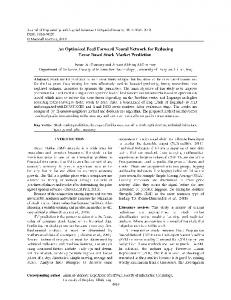
Fig. 2. Step2: Link layer RCPC coding.
3.1. FEC In the transport layer, we consider a systematic RS code to provide inter-packet protection. An RS code is represented as RS(n, k), where k is the number of source symbols and (n − k) the number of parity symbols. An RS(n, k) code can correct up to (n − k) erasures. A popular family of codes used to perform link-layer FEC with variable code rates are RCPC codes [8]. A family of RCPC codes is described by the mother code of rate 1/N and memory M . Together with N , the puncturing period P determines the range of code rates as R = P/(P + l) where l can vary between 1 and (N − 1)P . 3.2. Packetization In the product FEC scheme considered here, the first step is to perform RS coding at the transport layer. As shown in Fig. 1, we assume that the source bits in each transport packet correspond to one GOB (group of blocks) 1 and every packet is independently decoded. One GOB is directly packetized into one transport packet by the attachment of a transport packet header. Since the source packet sizes Bs,k (shown by the shaded area in Fig. 1) are usually different, the maximum packet size of a block (a group of packets protected by one RS code) is determined first, and then all packets are padded with stuffing bits in the tail part to make the sizes equal. The stuffing bits are removed after the parity packets are generated. Each source packet in Fig. 1 is protected by an RS(N , M ) code. %V ��
6WXIILQJ�ELWV�
%V � �
56� &RGLQJ�
*2%���
%F ��
%V ��
where Eb is the bit energy, N0 the noise power spectrum density, and a the expected value of the square of the Rayleigh fading [7]. Eb The average channel SNR is defined as SNR = a N . 0
�
F��
*2%���
3DFNHW���
In the link layer, each packet (including the parity packets) is padded with parity bits. As shown in Fig. 2, by using a particular RCPC code with rate rk , the length of packet k is then Bk = Bs,k + Bc,k = Bs,k /rk . Next, we discuss how to calculate the probability of loss for each source packet. Let Q, Γ, R, and P be the sets of allowable source coding parameters, RS coding parameter, RCPC coding parameters, and transmission power levels, respectively. Let µk ∈ Q, νk ∈ R, γ ∈ Γ, and ηk ∈ P represent the parameters selected for the k-th packet. Assuming independent bit errors (i.e., the additive noise and fading are each i.i.d. and independent of each other), the loss probability for a transport packet in the wireless channel can be calculated as βk (µk , νk , ηk ) = 1 − (1 − pb )Bk ,
(2)
where pb is the BER after RCPC decoding, and depends on pe in (1). Assuming the packet loss rate in the wired part is α, the overall loss probability of a transport packet in the network is then equal to �k (µk , νk , ηk ) = α + (1 − α)βk (µk , νk , ηk ). (3) Following the same notation used in [5], let Qtj (N ), j = 1, ..., N , � � t = 1, ..., Nj denote the t-th subset with j elements of Q(N ). For example, if N = 3, then Q(3) = {1, 2, 3}, Q11 (3) = {1}, Q21 (3) = {2}, Q31 (3) = {3}, Q12 (3) = {1, 2}, Q22 (3) = {1, 3}, Q32 (3) = {2, 3}, Q13 (3) = {1, 2, 3}. Let Ij (N, k) = {Qtj ∈ Q(N )|k ∈ Qtj (N ), |Qtj | = j}, then the loss probability of a source packet can be written as N (γ)
6WXIILQJ�ELWV�
�
ρk (µ, ν, η, γ) =
%V ��
Pb (N (γ), j)
j=N (γ)−M +1
⎛
%V � 0
6WXIILQJ�ELWV�
*2%�0� 3DFNHW�0�
%V � 1 ��
3DULW\�SDFNHW�
%V � 1
3DULW\�SDFNHW�
=
N �
�
j=N −M +1 Qt ∈Ij (N,k) j
�
Fig. 1. Step1: Transport layer RS coding. 1 As in the H.263 standard, we use GOB to denote one row of blocks in the following text.
⎞
⎜ ⎟ �i (1 − �l )⎠ , ⎝ i∈Qtj
(4)
l∈Qtj
where Pb (N, j) is the probability that the k-th packet is not correctly decoded by the RCPC decoder and the total number of transport packets that are not correctly received from the group of N packets is j. We let µ = {µ1 , µ2 , ..., µM } denote the vector of source coding parameters for the M source packets and ν = {ν1 , ν2 , ..., νN }, and η = {η1 , η2 , ..., ηN } the vector of RCPC coding rates and power levels for the N transport packets in a frame, respectively.
V - 858
➡
➡ 4. JOINT SOURCE-CHANNEL CODING AND POWER ALLOCATION 4.1. Problem Formulation By jointly considering error resilient source coding, FEC, power allocation, and error concealment, the JSCCPA problem is formulated as: M � min E[D] = E[Dk (µ, ν, γ, η)] {µ∈Q,ν ∈R,γ∈Γ,η∈P}
k=1 N (γ)
s.t. C =
�
Bk (µk , νk )Pk (ηk )/RT ≤ C0
(5)
k=1 N (γ)
T =
�
Bk (µk , νk )/RT ≤ T0 ,
k=1
where Bk and Pk are respectively the source bits and power level for the k-th packet; M and N are respectively the number of source packets and total transport packets in one frame; RT is the transmission rate; and C0 and T0 are the energy and transmission delay constraint for the frame, respectively. The expected distortion for the k-th packet is E[Dk ] = (1−ρk )E[Dr,k ]+ρk E[Dl,k ], where E[Dr,k ] and E[Dl,k ] are the expected distortion when the packet is either received correctly or lost, respectively, and ρk is the probability of loss for the k-th source packet in Eq. (4). Note that the calculation of Dl,k depends on the specific error concealment strategy used at the decoder. Assuming the mean squared error (MSE) criterion, the distortion measurement based on an algorithm called ROPE (Recursive Optimal Per-pixel Estimate) [9] is used to recursively calculate the overall expected distortion level of each pixel. 4.2. Solution Algorithm The optimization problem (5) is solved using Lagrangian relaxation. The search for correct Lagrange multipliers is achieved using the algorithm proposed in [6]. However, for given Lagrange multipliers, the minimization problem itself is still complicated due to the fact that the loss probability of one source packet depends on the operational parameters chosen for all the other packets. Hence, we solve the minimization problem by an iterative descent algorithm that is based on the method of alternating variables for multivariate minimization [10]. By adjusting one set of operational parameters for one packet at a time, while keeping constant those for the other packets until convergence, we can minimize the Lagrangian. Convergence is guaranteed because the Lagrangian is non-increasing and bounded below. For example, in our simulations, we have observed that it only takes two to three iterations for the Lagrangian to converge. The computational complexity mainly comes from the calculation of (4), which depends on the block size of the RS code.
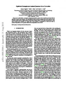
propagation, we assume that channel feedback is available to the encoder in the form of which packets are received or lost. Feedback is utilized in the calculation of the expected distortion (based on the ROPE algorithm) and limits the impact of error propagation. In all the experiments, the feedback delay is 4 frames (133.2ms) and the transmission rate is 360 Kbps. We emphasize that the feedback delay is long enough to preclude retransmissions in this setting. Rate control is not implemented in the video streaming system. Thus, every frame has the same transmission delay constraint of one frame time. The image quality is measured by the peak 2552 signal to noise ratio (PSNR), defined as = 10 log MSE dB. We choose Γ = {(9, 9), (11, 9), (13, 9), (16, 9)} as the available RS coding set, since longer blocks introduce longer delays. We use an RCPC code with generator polynomials (133, 171), mother code rate 1/2, and puncturing rate P = 4. This mother rate is punctured to achieve the 4/7, 2/3, and 4/5 rate codes. At the receiver, soft Viterbi decoding is used in conjunction with BPSK demodulation. We present experiments on Rayleigh flat-fading channels. The theoretical bounds of BER for RCPC codes can be found in [8,11]. The bit error rates for the Rayleigh fading with the assumption of ideal interleaving were obtained experimentally using simulations. The method for simulation can also be found in [8, 11]. In all the simulations, we assume that the transmission power level is fixed. This simplified case allows us to better analyze the potential of the PFEC approach in providing UEP. 5.2. Product FEC vs. Link-Layer FEC In this experiment, we compare the performance of two systems: 1) the proposed product code FEC (PFEC) and 2) pure link-layer FEC (LFEC). The goal is to illustrate the advantage of using product FEC. Both systems are UEP optimized using the proposed framework (5), where the PFEC system allows transport-layer RS coding but the LFEC system does not. Note that the two systems have the same transmission delay constraints. We illustrate the performance of the two systems in Fig. 3, where we plot the average decoded PSNR for various average SNR values in the wireless link and packet loss rates α in the wired link. As shown in Fig. 3, with the above simulation setup, when α is small, LFEC is close to PFEC. However, as the wired link gets worse, PFEC starts to outperform LFEC by up to 2.5 dB. This improved performance is due to the use of cross-packet protection in the transport layer. We have observed that when α increases, the LFEC system tends to allocate more redundant bits to the link layer, thus decreasing the probability of loss in the wireless link. Because link layer FEC does not provide inter-packet protection, it is less efficient than transport layer FEC at reacting to packet losses in the wired link. Another observation from Fig. 3(a) is that when α = 0, which corresponds to the case where the wired link is error free, the inter-packet FEC in the transport layer becomes unnecessary and thus the optimized PFEC is equivalent to LFEC. 5.3. UEP vs. EEP
5. EXPERIMENTAL RESULTS 5.1. Implementation Issues In our simulations, we choose an H.263+ codec and the test sequence is Foreman in QCIF (176×144) format at a frame rate of 30 fps. We employ a simple but efficient temporal replacement strategy for error concealment, i.e., at the decoder, the lost MB (macro-block) is replaced by the MB with the same spatial location in the previously reconstructed frame. In order to limit error
In the second experiment, we illustrate the advantage of UEP by comparing the performance of two systems: 1) UEP product FEC (UEP-PFEC) and 2) EEP product FEC (EEP-PFEC). Both systems use product FEC and are optimized within the JSCCPA framework. The difference is that the EEP system has fixed link layer FEC, while the link layer FEC for the UEP system is variable. For the two systems, we plot the average decoded PSNR under different average channel SNR in Fig. 4. It can be seen that UEP-PFEC
V - 859
➡
➠ 33
33
LFEC−−8dB PFEC−−8dB LFEC−−12dB PFEC−−12dB
32.5 32
32 31 30
31
PSNR(dB)
PSNR(dB)
31.5
30.5 30
26
29
25
28.5 28 0
0.05 0.1 0.15 Prob. packet loss in wired channel α
24 6
0.2
(a) 32 31.5
28 27
29.5
32.5
EEP−cr 1/2 EEP−cr 4/7 EEP−cr 2/3 EEP−cr 4/5 UEP
29
8
10
12 14 16 Average channel SNR (dB)
18
20
Fig. 4. PSNR vs. average channel SNR (α=0.1), for UEP and EEP.
LFEC−−α=0.1 PFEC−−α=0.1 LFEC−−α=0.2 PFEC−−α=0.2
FEC scheme in providing UEP. 7. REFERENCES
PSNR(dB)
31
[1] D. A. Eckhardt, An Internet-style approach to managing wireless link errors, Ph.D Thesis, Carnegie Mellon University, Pittsburg, PA, May 2002.
30.5 30
[2] G. Cheung, W.-T. Tan, and T. Yoshimura, “Rate-distortion optimized application-level retransmission using streaming agent for video streaming over 3G wireless network,” in Proceedings IEEE Inf. Conf. Image Processig, Rochester, New York, Sept. 2002.
29.5 29 28.5 28 6
8
10
12 14 16 Average channel SNR (dB)
18
20
[3] N. Celandroni and F. Potot`ı, “Maximising single connection TCP goodput by trading bandwidth for BER,” Int. J. of Commun. Syst., vol. 16, pp. 63–79, Feb. 2003.
(b) Fig. 3. (a) PSNR vs. α (b) PSNR vs. average channel SNR, for PFEC and LFEC.
[4] P. G. Sherwood and K. Zeger, “Error protection for progressive image transmission over memoryless and fading channels,” IEEE Trans. Comm., vol. 46, pp. 1555–1559, Dec. 1998.
achieves the upper bound of all EEP-PFEC systems, and outperforms the best of all EEP systems by around 0.2dB at all channel conditions. The gain comes from the higher flexibility of the UEP-PFEC approach, where link-layer coding parameters can be optimally assigned to different packets to achieve UEP for video packets that are of different importance. Table 1 shows how link layer FEC rates are selected in the UEP system. As we can see, as the channel SNR improves, less link layer protection is needed. SNR (dB) rate=1/2 rate=4/7 rate=2/3 rate=4/5
6 28.9 68.9 0.7 1.5
8 26.7 5.2 68.2 0
10 3.0 0 89.6 7.4
12 0.7 0 80.7 18.5
14 0.7 0 37.8 61.5
16 0.7 0 23.7 75.6
[5] V. Stankovi´c, R. Hamzaoui, and Z. Xiong, “Product code error protection of packetized multimedia bitstreams,” in Proc. IEEE ICIP, Barcelona, Spain, Sept. 2003. [6] F. Zhai, Y. Eisenberg, T. N. Pappas, R. Berry, and A. K. Katsaggelos, “Joint source-channel coding and power allocation for energy efficient wireless video communications,” in Proc. 41st Allerton Conf. Communications, Control, and Computing, Oct. 2003.
18 0 0 9.6 90.4
[7] T. S. Rappaport, Wireless communications principle and practice, Prentice Hall, 1998. [8] J. Hagenauer, “Rate-compatible punctured convolutional codes (RCPC codes) and their applications,” IEEE Trans. Commun., vol. 36, pp. 389–400, Apr. 1988.
Table 1. Link-layer FEC rates in percentage in UEP-PFEC system.
[9] R. Zhang, S. L. Regunathan, and K. Rose, “Video coding with optimal inter/intra-mode switching for packet loss resilience,” IEEE J. Select. Areas Commun., vol. 18, pp. 966– 976, June 2000.
6. CONCLUSIONS This paper is devoted to improving video delivery quality over IPbased wireless networks through cross-layer resource allocation. Specifically, we have proposed an algorithm that provides optimal UEP using product code FEC, which consists of RS coding in the transport layer and RCPC coding in the link layer. The optimal bit allocation is achieved in a JSCCPA framework. Through simulations, we have illustrated the advantages of using a product code
[10] R. Fletcher, Practical methods of optimization, New York: Wiley, 2nd edition, 1987. [11] J. G. Proakis, Digital Communications, McGraw-Hill, New York, Aug. 2000.
V - 860