REAL-TIME IMPLEMENTATION OF A SPHERE DECODER-BASED MIMO WIRELESS SYSTEM Mikel Mendicute† , Luis G. Barbero∗ , Gorka Landaburu† , John S. Thompson∗ , Jon Altuna† , and Vicente Atxa† † Communications and Digital Signal Processing Area Department of Electronics University of Mondragon Loramendi, 4, 20500 Mondragon, Spain e-mail:
[email protected]
ABSTRACT This contribution analyzes the integration of the sphere decoder (SD) in a complete field-programmable gate array (FPGA)-based real-time multiple input-multiple output (MIMO) platform. The algorithm achieves the performance of the maximum likelihood detector (MLD) with reduced complexity. However, its non-deterministic complexity, depending on the noise level and the channel conditions, hinders its integration process. This paper evaluates the performance and limitations of the SD in a real-time environment where signal impairments, such as symbol timing, imperfect channel estimation or quantization effects are considered. 1. INTRODUCTION The use of multiple input-multiple output (MIMO) technology in wireless communication systems enables high-rate data transfers and improved link quality through the use of multiple antennas at both transmitter and receiver [1]. It has become a key technology to achieve the bit rates that will be available in next-generation wireless communication systems, combining spatial multiplexing and space-time coding techniques [2]. In addition, the prototyping of those MIMO systems has become increasingly important in recent years to validate the enhancements advanced by analytical results [3], [4]. For that purpose, field-programmable gate arrays (FPGAs), with their high level of parallelism and embedded multipliers, represent a suitable prototyping platform. In the case of spatially multiplexed uncoded MIMO systems, the sphere decoder (SD) is widely considered the most promising approach to obtain optimal maximum likelihood (ML) performance with reduced complexity [5], [6]. The SD has been previously implemented in real-time [7], [8], indicating that its variable throughput could potentially represent a problem when integrating it into a complete communication system. However, the problem of the actual integration of the SD into a real-time MIMO system has not been addressed yet. This paper presents a complete real-time FPGA MIMO system where the SD has been used as the detection algorithm. The SD has been integrated into the MIMO prototyping platform presented in [9]. Thus, the effect real-time transmission impairments, like imperfect symbol timing and channel estimation or fixed-point precision, have been included in the performance evaluation of the SD.
∗ Institute for Digital Communications School of Engineering and Electronics University of Edinburgh EH9 3JL Edinburgh, UK e-mail:
[email protected]
2. SPHERE DECODER (SD) 2.1 MIMO System Model The theoretical system model considered has, in the general case, M transmit and N receive antennas, with N ≥ M, denoted as M × N. The transmitted symbols are taken independently from a quadrature amplitude modulation (QAM) constellation of P points. Assuming symbol-synchronous receiver sampling and ideal timing, the received N-vector, using matrix notation, is given by r = Hs + n
(1)
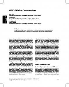
where s = (s1 , s2 , ..., sM )T denotes the vector of transmitted symbols with E[|si |2 ] = 1/M, n = (n1 , n2 , ..., nN )T is the vector of independent and identically distributed (i.i.d.) complex Gaussian noise samples with variance σ 2 = N0 and r = (r1 , r2 , ..., rN )T is the vector of received symbols. H denotes the N × M channel matrix where hi j is the complex transfer function from transmitter j to receiver i. The entries of H are modelled as i.i.d. Rayleigh fading with E[|hi j |2 ] = 1 and are perfectly estimated at the receiver. 2.2 SD Algorithm The main idea behind the SD is to reduce the computational complexity of the maximum likelihood detector (MLD) by searching over only those noiseless received points (defined as Hs) that lie within a hypersphere of radius R around the received signal r. In this paper, the complex version of the SD is applied directly to the complex lattice Λ(H) = {Hs} [10]. Avoiding the more common real decomposition of the system results in a more efficient hardware implementation [8]. The process can be represented by ˆ sml = arg{min kr − Hsk2 ≤ R2 } . s
(2)
and is shown in Figure 1, where the dots represent the noiseless received constellation and the cross represents the actual received point contaminated with noise. The sphere constraint in (2) can also be written, after matrix decomposition and removal of constant terms, as kU(s −ˆ s)k2 ≤ R2
(3)
where U is an M × M upper triangular matrix, with entries denoted ui j , obtained through Cholesky decomposition of the Gram matrix G = HH H (or, equivalently, QR decomposi-
3. MIMO PROTOTYPING PLATFORM AND TOOLS
R
Figure 1: Schematic of the sphere decoder principle for the 2-dimensional case - only the points inside the circle are searched tion of H) and ˆ s = (HH H)−1 HH r is the unconstrained ML estimate of s [10]. The solution of the sphere constraint (SC) in (3) can be obtained recursively using a tree search algorithm, starting from i = M and working backwards until i = 1. For each level, the constellation points si that satisfy |si − zi |2 ≤
Ti u2ii
(4)
are selected as partial ML candidates, where M
zi = sˆi − and Ti = R2 −
ui j (s j − sˆ j ) j=i+1 uii
∑ M
∑
u2j j |s j − z j |2 .
(5)
(6)
j=i+1
When a new point is found inside the hypersphere (at i = 1) the radius is updated with the new minimum Euclidean distance and the algorithm continues the search with the new SC. This process can be seen as a tree search through M levels where each node on each level contains P branches. If Ti ≤ 0, in any level i, the squared Euclidean distance from the root to that node has exceeded the SC and the entire branch plus all its descendants can be discarded, yielding a speed increase compared to an exhaustive search. The search finishes when the radius has been reduced so that no more points are found that satisfy the SC: the last point found satisfying the SC is the ML solution ˆ sml . In order to further reduce the complexity of the SD, the points that satisfy (4) are searched according to increasing distance to zi , following the Schnorr-Euchner (SE) enumeration [11]. The use of this enumeration has two effects: • On a particular node, The SE enumeration follows the branches with lowest distance increment |si − zi |2 first in any level i. Thus, the first points searched are more likely to be the ML solution, reducing the overall complexity of the search. • Although the initial radius R is normally set according to the noise variance per antenna σ 2 , the use of the SE enumeration reduces the effect the initial radius has on the complexity of the SD. From a simulation point of view, the initial radius still has a marginal effect on the complexity of the SD [6]. However, in a parallel implementation of the algorithm, the initial value can be set to the end of the scale so that no estimate of the noise level is required at the receiver [8].
The MIMO system and algorithms described in this paper have been implemented on a rapid prototyping platform based at the University of Mondragon. This platform, whose main features and operating modes have been previously presented in [9], consists of the following three elements: HERON rapid prototyping boards from Hunt Engineering Ltd. [12], RF transceivers and software tools. 3.1 Rapid Prototyping Boards The platform is based on modular rapid prototyping HERON HEPC9 boards. The main advantage of those peripheral component interconnect (PCI)-based carrier cards consists of its very flexible architecture, based on an internal bus which allows communication of up to 400 mega bytes per second (MBps) between the modules. The following modules have been chosen for the implementation described in this work: • Two HERON-IO2V2 modules with 4 analog inputs and 4 analog outputs of up to 125 mega samples per second (MSPS) with 12 and 14 bits of resolution, respectively. These modules include a 1-million (M)-gate Xilinx VirtexII FPGA and allow real-time in-system debugging with Xilinx Chipscope [13]. In addition, it is possible to perform co-simulation in a MATLAB/Simulink environment for Xilinx System Generator-based designs [14]. • One HERON-IO5 module with 2 analog inputs and 2 analog outputs of up to 210 MSPS with 12 and 16 bits of resolution, respectively. This module includes a 3M-gate VirtexII FPGA, which also contains a JTAG debugging interface. • One HERON-FPGA3 module with a 1M-gate VirtexII FPGA. 3.2 RF Transceivers The platform is equipped with Maxim’s MAX2827EVKit boards, which can transmit or receive radio frequency (RF) signals in the 2.4 and 5 GHz bands. These transceivers can modulate and demodulate baseband IQ signals of a bandwidth of up to 20 MHz. This solution avoids the need for an implementation of algorithms such as modulators, digital up converters, etc., in order to generate the analog signals required by a transceiver. The combination of the analog ports of the aforementioned prototyping boards and these transceivers allow the implementation of systems with up to three transmit and receive antennas. Figure 2 shows two of these RF transceivers with the HEPC9-based rapid prototyping platform. 3.3 Software Design and Simulation Tools A combination of MATLAB/Simulink and Xilinx System Generator has been selected as the main design tool to allow co-simulation of MATLAB algorithms, simulated VHDL implementations and FPGA-running blocks. This solution offers a simple and intuitive GUI-based hardware design and simulation tool for DSP algorithm engineers, achieving a balance between hardware abstraction level and real-time performance. All the algorithms mentioned in this paper have been first tested in MATLAB and then translated to hardware blocks using Xilinx System Generator. Once the design has
TX 1
QAM MAP
TX 2
2x2 Wireless Channel H
RX 1
RX 2
SYN C H R ON I ZA T ION
Input Bits
QAM MAP
SPHERE DECODER
Cholesky Pinv Detected Bits
CHANNEL ESTIMATION
Figure 3: Structure of a basic 2×2 MIMO spatial multiplexing system.
Figure 2: Main elements of the HEPC9-based MIMO signal processing prototyping platform. been completed, Xilinx synthesis tools have been used to generate the bitstreams required for the hardware-based cosimulation, as well as the VHDL netlists for the final implementation. Xilinx Chiscope has been selected as the realtime on-hardware debugger. 4. REAL-TIME MIMO IMPLEMENTATION 4.1 MIMO System Model and Algorithms 4.1.1 System Model Figure 3 shows the basic 2×2 MIMO spatial multiplexing model that has been implemented. The data bits are split into two 16-QAM streams which are transmitted independently and received synchronously at the two receive antennas. A complete MATLAB-based model has been created and adapted to Simulink. A burst frame-based transmission system has been assumed with 128 data symbols transmitted per antenna. In addition, a 32-symbol preamble is transmitted per antenna to allow for effective synchronization and channel estimation to be performed at the receiver. The analog to digital converters (ADCs)’ 12-bit resolution has been chosen for the precision of the input signals. 4.1.2 Algorithms The following algorithms have been implemented: • Frame synchronization: a multi-antenna extension of the double-sliding window technique has been applied [15]. • Sample-time synchronization: an ML approach has been chosen according to [16]. • Frequency Offset Estimation: a reduced complexity iterative offset estimation technique has been used as in [17]. • Channel Estimation: a basic training-based LS (LeastSquares) MIMO channel estimator has been implemented. • Inverse calculation and normalized Cholesky decomposition: required by the SD for the initial zero forcing (ZF) equalization and the tree search. • MIMO detection: The SD algorithm described in section 2 has been implemented with System Generator and included in the MIMO design. Details of the implementation can be found in [7] for a 4×4 system.
Figure 4: Top-level block diagram of the implemented MIMO receiver • Inline MIMO channel emulator: A flat Rayleigh channel emulator has been created to allow hardware cosimulation of the full system. This channel emulator is based on Gaussian noise generators and channel coefficients stored in a large RAM block. This allows to test the hardware implementation at its maximum rates without breaking the flat-fading channel assumption. 4.2 High-Level Design and Hardware Co-Simulation A fully flexible hardware co-simulation system has been implemented, allowing the progressive testing of the SD algorithm. The following implementation steps have been executed in order to evaluate the effect of real-communication impairments and quantization on the performance of the SD: • Ideal simulation: The first simulation system, with perfect synchronization, known channel and no filters has been implemented initially to validate the integration of the SD and the 12-bit quantization error floor. • Estimated channel, real-time calculated inverse and Cholesky: This version has been implemented to evaluate the effects of imperfect channel estimation and fixedpoint calculations when obtaining the Cholesky decomposition and the inverse of the channel. • Complete System: A final system has been implemented with all the algorithms required to interface with the real RF transceiver signals or the hardware-emulated channel. Figure 4 shows the top-level block diagram of the MIMO receiver implemented with System Generator.
FPGA
FPGA
H EA R T B U S
VirtexII 1M
SPHERE DECODER
DEMAP
DAC 2
IO
i tx1
i
tx2
CHANNEL ESTIMATION
MAP + PREAMBLE
PINV CALCULATION
q
VirtexII 1M
TX FILTER
CHOLESKY DECOMP.
Algorithm
DAC 4
IO
tx2
VirtexII VirtexII 1M 1M
VirtexII 3M
SYNC RX FILTER
i rx1
PCI INTERFACE
q tx1
DAC 3
ADC 1
q rx1
ADC 2
i rx2
ADC 3
q rx2
ADC 4
Figure 5: Structure of a 2×2 real-time MIMO implementation on the HERON modules of the HEPC9 board. 4.3 Final Real-Time Implementation Figure 5 shows a diagram of the HEPC9 implementation of the 2×2 MIMO system with the distribution of the signal processing algorithms through the Heron modules available. The resource use has been distributed among four FPGA modules, which are connected through HEPC9’s data bus. All the data flow of the real-time system is controlled through the PCI bus by a C++ application running on a host PC. Although the system can run at a higher symbol rate, we have reduced it to 100 kilo symbols per second (ksps) to allow for the flat-fading channel assumption of (1) to be valid with real transmission. Higher symbol rates can still be tested on the platform with the inline channel emulator.
Slices
% Slices
0 74 18 33 23 20 0
1,320 11,923 2,693 4,608 3,370 1,771 1,542
5.3% 48.3% 10.9% 18.6% 13.7% 7.2% 6.2%
Total Used Total Available
96 216
16,556 24,696
67.0%
Table 1: FPGA Resources used by the final real-time implementation. BER Performance of the SD (M = N = 2, 16−QAM)
0
10
−1
10
−2
10
−3
10
5. RESULTS Table 1 shows the FPGA resources of the complete MIMO system using 16-QAM modulation. For clarity purposes, only the number of multipliers and slices are shown. They are compared against the total number of multipliers and slices available on the HEPC9 boards. The three main blocks of the receiver are also shown to indicate the distribution of the resources. The calculation of the inverse of the channel matrix and the Cholesky decomposition of the Gram matrix are the most computationally intensive tasks. It should be noted that those two operations have not been optimized from an implementation point of view given that the focus of this work was on the integration of the SD in a MIMO system. The implementation of the SD requires a relatively small FPGA area, indicating that several SDs could be implemented in parallel on the same prototyping platform. The algorithm named ’Comm. & Control’ corresponds to the logic required for the inter-module data communication and the PCI-based control of the real-time execution flow. The bit error ratio (BER) performance as a function of the signal to noise ratio (SNR) per bit of the different versions of the system is shown in Figure 6. The results have been measured using the FPGA-based channel emulator, averaging over 5,000 channel realizations. Five curves, representing the different implementation stages are shown, together with the floating-point MATLAB version of the SD. It can be seen how the quantization process causes an error floor to appear at high SNR, which is larger when 12 bits are used for the input data instead of the initial 16 bits (considering ideal channel estimation and floating-point matrix calculations in both cases). The BER performance additionally degrades when the channel estimation block is added and fixed-point inverse and Cholesky calculations are performed.
Mults
Transmitter Receiver Sync & Ch. Est. Inv. & Chol. SD Ch. Emulator Comm. & Control
BER
HE P C9
DAC 1
SD (MATLAB) SD (FPGA) − 16 bits SD (FPGA) − 12 bits SD (FPGA) − 12 bits − Ch. Est. SD (FPGA) − 12 bits − Ch. Est. + Filt.
−4
10
0
5
10
15
20
25
Eb/N0 (dB)
Figure 6: BER of the SD at different implementation stages Finally, the last curve represents the BER performance of the complete system when transmit and receive filters are added. It can be seen how the quantization process and the effect it has on the channel estimation and the matrix calculations are the main factors determining the BER performance degradation compared to an ideal system. Figure 7 shows the throughput of the SD for the aforementioned implementation levels. The throughput in mega bits per second (Mbps) is calculated according to Qavg = M · log2 P · fclock /Cavg (Mbps)
(7)
where fclock is the clock frequency of the system in MHz and Cavg is the average number of clock cycles required to detect a MIMO symbol. The maximum clock frequency of the SD, fclock = 50 MHz, has been considered for the calculations although real transmission has been performed at a lower frequency. The minimum number of cycles is Cmin = 13 resulting in a maximum throughput Qmax = 30.77 Mbps. It can be seen how the 16-bit implementation of the SD approximates Qmax at high SNR per bit. A lower throughput is achieved by the other systems due to the effect the quantization has on the tree search of the SD. It causes some additional paths of the tree to be searched, slowing down the detection of the symbols. The degradation in performance is larger at high
Government through Researcher Training Grants BFI03.378 and BFI05.428. The second author’s work is partially sponsored by Alpha Data Ltd.
Average Throughput of the SD (M = N = 2, 16−QAM) 32 30
Throughput (Mbps)
28 26
REFERENCES
24
[1] G. J. Foschini, “Layered space-time architecture for wireless communication in a fading environment when using multielement antennas,” Bell Labs Technical Journal, pp. 41–59, Oct. 1996.
22 20 18
14 12 −5
[2] C. Kose and B. Edwards, “WWiSE proposal: High throughput extension to the 802.11 standard,” 11-05-0149-00-000n. [Online]. Available: http://www.wwise.org/technicalproposal.htm
SD (FPGA), 16 bits SD (FPGA), 12 bits SD (FPGA), 12 bits, Ch. Est. SD (FPGA), 12 bits, Ch. Est. + Filt.
16
0
5
10 15 Eb/N0 (dB)
20
25
30
Figure 7: Throughput of the SD at different implementation stages SNR per bit where the quantization noise is larger than the Gaussian noise. Finally, more SDs could be implemented in parallel to increase the average throughput like in [7],[8]. 6. CONCLUSION AND FUTURE WORK This paper has analyzed the integration of the SD in a realtime MIMO system where actual impairments, such as imperfect channel estimation, quantization and synchronization effects are considered. A 2×2 low-rate system has been developed using Xilinx System Generator in order to obtain BER and throughput results, evaluating the performance of the SD at several implementation steps. The main conclusions from this work can be summarized as: • The BER performance of the SD on the FPGA approximately matches that of MATLAB, except at high SNR. The difference appears due to the fixed-point precision used for the input data and for the operations performed to obtain the input matrices (channel inverse and Cholesky decomposition). • The throughput of the SD decreases as the system approaches a realistic transmission and reception case. A throughput loss of approximately 6% has been observed at high SNR. • The MIMO platform and tools have been proved to be very practical in order to test the validity of the SD implementation in a real MIMO system. The homogeneity of the design flow has favoured the integration of the work of the two research groups involved. As future work lines, the results of this paper can be extended to larger MIMO systems where additional resources would be required. In addition, a more detailed analysis of the fixed-point precision blocks could help identifying what the main causes of the quantization errors are. Finally, the inclusion of a robust channel equalizer and adaptive channel estimation could help evaluating the SD in higher rate transmissions with larger data bursts. Acknowledgements The first and third authors’ work is supported by the Department of Education, Universities and Research of the Basque
[3] M. Rupp, A. Burg, and E. Beck, “Rapid prototyping for wireless designs: the five-ones approach,” Signal Processing, vol. 83, pp. 1427–1444, 2003. [4] T. Kaiser, A. Wilzeck, M. Berentsen, and M. Rupp, “Prototyping for MIMO systems: An overview,” in Proc. 12th European Signal Processing Conference (EUSIPCO ’04), Viena, Austria, Sept. 2004. [5] E. Viterbo and J. Boutros, “A universal lattice code decoder for fading channels,” IEEE Trans. Inform. Theory, vol. 45, no. 5, pp. 1639–1642, July 1999. [6] M. O. Damen, H. E. Gamal, and G. Caire, “On maximumlikelihood detection and the search for the closest lattice point,” IEEE Trans. Inform. Theory, vol. 49, no. 10, pp. 2389– 2402, Oct. 2003. [7] L. G. Barbero and J. S. Thompson, “Rapid prototyping of the sphere decoder for MIMO systems,” in Proc. IEE Conference on DSP Enabled Radio (DSPeR ’05), vol. 1, Southampton, UK, Sept. 2005, pp. 41–47. [8] A. Burg, M. Borgmann, M. Wenk, M. Zellweger, W. Fichtner, and H. B¨olcskei, “VLSI implementation of MIMO detection using the sphere decoding algorithm,” IEEE J. Solid-State Circuits, vol. 40, no. 7, pp. 1566–1577, July 2005. [9] M. Mendicute, J. Altuna, G. Landaburu, and V. Atxa, “Platform for joint evaluation of FPGA-implemented and MATLAB algorithms in real MIMO transmissions,” in Proc. IEE Conference on DSP Enabled Radio (DSPeR ’05), vol. 1, Southampton, UK, Sept. 2005, pp. 31–34. [10] B. M. Hochwald and S. ten Brink, “Achieving near-capacity on a multiple-antenna channel,” IEEE Trans. Commun., vol. 51, no. 3, pp. 389–399, Mar. 2003. [11] C. P. Schnorr and M. Euchner, “Lattice basis reduction: Improved practical algorithms and solving subset sum problems,” Mathematical Programming, vol. 66, pp. 181–191, 1994. [12] Hunt Engineering Ltd., “http://www.hunteng.co.uk.” [13] Xilinx, Inc., “http://www.xilinx.com.” [14] The MathWorks, Inc., “http://www.mathworks.com.” [15] J. Heiskala and J. Terry, OFDM Wireless LANs: A Theoretical and Practical Guide. Indiana, USA: Sams Publishing, 2002. [16] A. F. Naguib, V. Tarokh, N. Seshadri, and A. R. Calderbank, “A space-time coding modem for high-data-rate wireless communications,” IEEE J. Solid-State Circuits, vol. 16, no. 8, pp. 1459–1478, Oct. 1998. [17] F. Simoens and M. Moeneclaey, “A reduced complexity frequency offset estimation technique for flat fading mimo channels,” in Proc. IEEE CAS Symposium on Emerging Technologies.