TetSplat: Real-time Rendering and Volume Clipping of Large Unstructured Tetrahedral Meshes Ken Museth∗
Santiago Lombeyda†
Link¨ oping Institute of Technology
California Institute of Technology
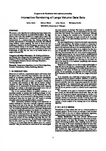
Figure 1: Screen shots from interactive visualization of an unstructured 275Mb mesh with more than 5 million tetrahedra and 13 field values. Our method is the first to guarantee real-time performance regardless of rendering hardware (here a P4 1.7GHz, Radeon 8700) and size of the unstructured tetrahedral mesh. Images show real-time volumetric clipping by CSG intersection with a sphere probe (left), cutting plane (two center) and a box probe (right).
A BSTRACT
1
We present a novel approach to interactive visualization and exploration of large unstructured tetrahedral meshes. These massive 3D meshes are used in mission-critical CFD and structural mechanics simulations, and typically sample multiple field values on several millions of unstructured grid points. Our method relies on the preprocessing of the tetrahedral mesh to partition it into non-convex boundaries and internal fragments that are subsequently encoded into compressed multi-resolution data representations. These compact hierarchical data structures are then adaptively rendered and probed in real-time on a commodity PC. Our point-based rendering algorithm, which is inspired by QSplat, employs a simple but highly efficient splatting technique that guarantees interactive frame-rates regardless of the size of the input mesh and the available rendering hardware. It furthermore allows for real-time probing of the volumetric data-set through constructive solid geometry operations as well as interactive editing of color transfer functions for an arbitrary number of field values. Thus, the presented visualization technique allows end-users for the first time to interactively render and explore very large unstructured tetrahedral meshes on relatively inexpensive hardware.
A well studied and yet prevailing problem in scientific visualization is the interactive rendering and exploration of large-scale volumetric datasets. Most of this work has been devoted to volume rendering of large structured (i.e. regular) and often uniformly sampled 3D data-sets with trivial convex boundaries. This is a simple consequence of the fact that structured volumetric data-sets are the ones most typically encountered in scientific visualization. However, the advances of computational multi-resolution techniques combined with the ever increasing speeds of computing hardware have created a growing need for new interactive visualization techniques for unstructured (i.e. irregular) volumetric data-sets. In this paper we focus on a new real-time visualization technique for large unstructured tetrahedral meshes with multi-dimensional field values and non-convex boundaries. The proposed method renders the massive volumetric data as opaque surfaces with CSG cuts. This work should not be viewed as an alternative to the large body of work on translucent rendering techniques for regular grids. Our visualization framework, dubbed TetSplat to acknowledge it’s source of inspiration (QSplat), was developed as an invaluable tool for scientists at Caltech’s “ASCI/ASAP Center for Simulation of the Dynamic Response of Material”. The focus of the research at this center is the study of propagating shock-waves across target materials inside an exploding virtual cannister, using large-scale coupled computational fluid dynamics (CFD) and solid mechanics computations. The result of these simulated explosions are often very large unstructured tetrahedral meshes with multiple field values (like density, pressure, temperature etc) which simply cannot be directly rendered in real-time for fast inspection and validation. As such the work presented in this paper grew out of a real need for a flexible visualization tool that can run at interactive speeds on inexpensive PCs. Few commercial or opensource products exist today for rendering of large tetrahedral meshes (e.g. EnSightTM and ParaView), but they require very expensive visualization hardware (like shared memory supercomputers) to achieve interactive speeds. Our approach is to use a combination of pre-processing with lossy compression to build up compact hierarchical data structures and fast point-based rendering with adaptive resolution to guarantee real-time performance regardless of the size of the input mesh
CR Categories: I.3.3 [Computer Graphics]: Picture/Image Generation—Display Algorithms; I.3.5 [Computer Graphics]: Computational Geometry and Object Modeling—Constructive Solid Geometry; I.3.5 [Computer Graphics]: Computational Geometry and Object Modeling—Curve, surface, solid, and object representations; I.3.6 [Computer Graphics]: Methodology and Techniques—Graphics data structures and data types; Keywords: Large volumetric data, tetrahedral meshes, real-time visualization, point-based rendering, constructive solid geometry. ∗ e-mail:
† e-mail:
[email protected] [email protected]
IEEE Visualization 2004 October 10-15, Austin, Texas, USA 0-7803-8788-0/04/$20.00 ©2004 IEEE
I NTRODUCTION
433
and the available rendering hardware. This approach allows us to make maximum use of our limited hardware resources. The preprocessing can either be performed in parallel on the computational CPU nodes that each store a fragment of the large tetrahedral mesh, or alternatively on a single high-end workstation. The visualization on the other hand can be performed on a desktop, or even laptop, with or without dedicated graphics hardware. 1.1
Previous work
To the best of our knowledge there is no previous work that can claim real-time performance for multi-resolution rendering and volumetric clipping of large unstructured tetrahedral meshes. Hence, relevant previous work is limited to publications on very different approaches to visualizing tetrahedral meshes as well as selected work on real-time techniques for rendering large surface meshes. In fact, the previous work most related to ours (see below) has very little, if anything, to do with visualization of tetrahedral meshes since they describe real-time techniques developed for 2D meshes. Foremost TetSplat is based on the excellent work by [18] which describe a relatively simple but extremely efficient point-based rendering technique for real-time visualization of large surface meshes. Their method (QSplat) pre-computes a compact hierarchical data structure from the input mesh which can subsequently be rendered in real-time by adaptive point splatting. Specifically they use a hierarchy of bounding spheres [17, 2] and normal cones [20] to allow for fast visibility culling and level-of-detail control when traversing an unbalanced quad-tree that serves as the multi-resolution data representation of the surface mesh. However it should be noted that the idea of using points for surface rendering [16, 13] and volume rendering by splatting[15] predates QSplat. TetSplat is also inspired by the recent work of [1] on interactive boolean operations between closed surfaces represented with surfels (i.e. oriented points). They use balanced (i.e. regular) octrees of the surfels to perform fast constructive solid geometry[7] (CSG) operations. They also employ a simple but clever re-sampling technique to improve the rendering of surfels along the intersection curve. In the past few years there have been several graphics related publications using tetrahedral meshes, but most of this work deals with incremental mesh simplification[12, 21, 4] and multiresolution modeling[22, 10] using regular tetrahedral meshes. In fact, [5] states that there does not seem to be any work on multiresolution visualization of unstructured tetrahedral meshes published prior to their recent publication. As they point out it is difficult, if not impossible, to generalize techniques developed specifically for structured meshes to unstructured tetrahedral meshes due to non-convex boundaries and varying sizes of grids cells in the latter. [5] describes iso-surface mesh extraction from a compact multiresolution data structure of moderately sized unstructured tetrahedral meshes built through edge collapses[4]. 1.2
Contributions
We present a novel technique for interactive visualization of large unstructured tetrahedral meshes. The features and benefits of our visualization framework (dubbed TetSplat) can be summarized as: • Real-time rendering of unstructured tetrahedral meshes regardless of size and the available computing resources. • Pre-processing of tetrahedral mesh to partition it into compact hierarchical data structures of non-convex boundaries and internal fragments. • Real-time volumetric clipping by means of CSG culling during traversal and rendering of compact hierarchical data structures.
434
• Interactive editing of color transfer functions for an arbitrary number of field values. This work stands apart from previous work in several ways. None of the methods discussed in the previous section are capable of realtime rendering of large unstructured tetrahedral meshes. However we would like to stress that the approach presented in this paper is not intended as a replacement of all visualization techniques developed for moderately sized and/or structured tetrahedral meshes. The interactive techniques mentioned in the previous section were explicitly developed for real-time rendering and clipping of 2D surface. As such our work can be viewed as a 3D extension of some of the ideas presented in [18] and [1]. Specifically these technical extensions include different data structures optimized for the 3D mesh and real-time rendering with new features such as CSG culling with adaptive resolution of intersections and interactive color-mapping of multiple field values. 2
P RE - PROCESSING OF THE T ETRAHEDRAL M ESH
The first stage of our visualization pipeline is the off-line preprocessing of the large tetrahedral mesh to construct a compact multi-resolution data structure that can efficiently be rendered and clipped in real-time. This pre-processing in turn consists of three logical steps. First we partition the input tetrahedral mesh into nonconvex boundaries and interior parts. Throughout the remaining of this paper we shall refer to these parts respectively as the Shell and the Solid. Next we use this Shell and Solid to derive corresponding leaf nodes that are finally combined in two distinct hierarchical tree structures to form the multi-resolution data representations. The subsequent sections describe the details of these three steps of the pre-processing. 2.1 Partitioning the Input Mesh into the Shell and the Solid Since we plan to use an adaptive rendering technique based on splatting of opaque hierarchical bounding spheres we are faced with two fundamental issues. The first one is how to derive bounding spheres and normal information from the tetrahedral mesh, which is the topic of the next section. The second issue, and equally important, is how to efficiently construct compact data structures from these bounding spheres that can be interactively rendered at a decent quality, while also allowing for clipping using a virtual CSG probe. Part of the key to resolving this problem comes from the basic but crucial premise that we are rendering opaque surfaces as derived from topologically distinctive parts of the input mesh. The non-convex boundary of the tetrahedral mesh can be treated as a simple triangulated surface mesh with normals and multiple field values defined at the associated vertices. However, the interior parts of the input mesh will only be visible on the surface of the intersecting CSG probe. Consequently, normal information needed for the shading of the interior should be derived from the CSG probe itself and not from the tetrahedral mesh. The corresponding data structure for the 3D interior mesh should also reflect the fact that the topology is very different from the 2D boundary mesh. This all suggests that we first partition the tetrahedral mesh into a Shell and a Solid, as is described in Algorithm 1. Note that in order to facilitate a better rendering of the CSG intersection between the Shell and the Solid we also derive extra information indicating whether a particular tetrahedron or triangle in the Solid is located in the immediate proximity of the Shell boundary. 2.2 Deriving leaf nodes from the Shell and Solid In order to construct hierarchical tree structures for real-time rendering and clipping of the Shell and Solid, as defined in the previous section, we have to derive the leaf nodes from the corresponding sub-meshes. Since the tree structures will be based on hierarchical bounding spheres, we clearly need to define a center and a radius for
foreach (tetrahedra Tetk ) do Triki ← extract four triangles from Tetk ; Tri[4 ∗ k + i] ← sort indexes in vertex list of Triki ;
1) Needle
end Sort Tri according to the indexed vertex list of each triangle; foreach (triangle Triki ∈ Tri) do Triki ← Tri[n]; if (vertex list of Triki = vertex list of Tri[n + 1]) then Triki ∈ Solid; else
Triki ∈ Shell; Tetk is a boundary tetrahedron;
1) Spindle
3)
Triki is an internal triangle in the Solid;
end
1) Sliver
Algorithm 1: Pseudo-code for the partitioning of the input tetrahedral mesh into a triangular surface mesh called the Shell and triangular solid mesh called the Solid. Tri is an array of all triangles derived from the tetrahedral mesh. each leaf node in addition to storing all field values of interest. It is especially important to assign proper values for the radius in order to avoid holes during rendering. Additionally, for the Shell leaf nodes we need to define normal vectors. Below we shall present different strategies to deriving this information from the Shell and Solid. Tetrahedra: For the Solid part of the tetrahedral mesh the first obvious choice of a geometric primitive from which to derive the leaf nodes is of course the individual tetrahedra. The center and radius of the corresponding bounding sphere can then simply be defined as the circum-center and circum-radius of the tetrahedra. If a, b, c and d denote the coordinates in ℜ3 of the four vertices of a tetrahedron the circum-center relative to vertex a is given by [19] mtet =
2)
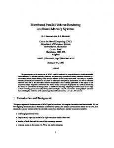
(b) Degenerate tetrahedra with a single large dihedral angle - so called spindles - are removed by splitting the edge opposite to the large angle and then collapsing the shortest edges.
end foreach (triangle Triki ∈ Solid) do if (Tetk is a boundary tetrahedron) then Triki is a boundary triangle in the Solid;
end
3)
(a) Degenerate tetrahedra without large dihedral angles - so called needles - are removed by collapsing the shortest edges.
end
else
2)
|d − a|2 A(b, c) + |c − a|2 A(d, b) + |b − a|2 A(c, d) , [b − a]x [b − a]y [b − a]z 2 [c − a]x [c − a]y [c − a]z [d − a]x [d − a]y [d − a]z
(1)
where we have introduced the following compact vector notation A(u, v) = (u − a) × (v − a)
(2)
and where for any vector u, [u]k denotes the kth component. The circum-radius is then simply given by |mtet | and the absolute coordinates of the circum-center are a + mtet . Since Eq. (1) is purely a function of differences between coordinates the relative error incurred in the numerical computation is not influenced by the absolute coordinates of the vertices. This is clearly an advantage since the vertices are usually nearer to each other than to the origin. Eq. (1) is only unstable if the denominator is close to zero which arises if the tetrahedron is nearly degenerate (i.e. flat or needle shaped). Whereas it is tempting to simply use more advanced and stable algorithms to compute the determinant [8], that doesn’t
2)
3)
(c) Degenerate tetrahedra with two large dihedral angles - so called slivers - are removed by introducing a new vertex that subdivides both edges containing the large angles and then collapsing the resulting shortest edge.
1) Cap
2)
3)
(d) Degenerate tetrahedra with three large dihedral angles - so called caps - are removed by introducing a new vertex in the face opposite to the three angles and then collapsing the resulting shortest edge. Figure 2: Recipes for collapsing degenerate tetrahedra characterized by the number of large dihedral angles (circular magenta arrows). New edges and vertices are colored green and short edges that are collapsed are colored red.
really address the fact that circum-spheres are generally not a very meaningful choice of bounding primitive for long or flat degenerate tetrahedra. A better strategy in our implementation is simply to remove the degenerate tetrahedra all together. This is primarily motivated by the fact that degenerate tetrahedra have very small volumes compared to their neighboring non-degenerate cells. Consequently removing a degenerate tetrahedra by collapsing it into its neighbors will introduce very small changes in the final point-based rendering. The degeneracy of the tetrahedra is quantified by their aspect ratio which is defined as the minimum height divided by the maximum edge length. Degenerate tetrahedra can be classified according to their shape as measured by the numbers of large dihedral angles it contains. This leads to four characteristic shapes called needles, spindles, slivers, and caps. Our strategy is to collapse degenerate tetrahedra by a simple series of edge splits and removals as described in figure 2(a) to 2(d). To ensure consistency it is recommended to collapse the degenerate tetrahedra from the input mesh before it is partitioned into the Shell and Solid. Since tetrahedra are only present in the Solid the normal vec-
435
tors of the corresponding splats will be derived directly from the CSG intersections. The data attributes on the other hand are readily defined as averages of the values defined at the corresponding vertices of the tetrahedra. Triangles: For the Shell and Solid, we can alternatively use the triangles as the geometric primitives from which to derive leaf nodes. If a, b and c denote the coordinates in ℜ3 of the three vertices of a triangle the circum-center relative to vertex a can conveniently be expressed as [19] mtri =
|c − a|2 A(b, c) × (b − a) + |b − a|2 (c − a) × A(b, c) 2 |A(b, c)|2
, (3)
where we have used the compact vector notation in Eq. (2). The circum-radius is simply given by |mtri | and the absolute coordinates for the circum-center are a + mtri . Note that Eq. (3) has the same numerical characteristics as Eq. (1). It is also expressed in differences of coordinates rather than the absolute values which can potentially be very small, and the denominator also vanishes when the triangles are near degenerate (i.e. vertices are co-linear). Whereas there exist several methods for eliminating degenerate triangles from surface meshes [3], a simpler and more consistent strategy in our case is first to collapse all degenerate tetrahedra, using the procedure described above, and then extract non-degenerate triangles from that. For any remaining obtuse triangles we found it sufficient to approximate the circum-center by the midpoint of the longest edge and the corresponding circum-radius as half the length. The orientation of splats derived from triangles is obviously trivial if we use the normal vector of the triangle face, and data attributes can simply be defined as averages of the values at the vertices. Vertices: As a last alternative we can derive the leaf nodes directly from the vertices of the mesh which is the strategy used in QSplat [18]. The center and field values of the corresponding bounding spheres are simply given by the coordinate and data attributes of the vertices. However, unlike for tetrahedra and triangles there is no intuitive and unique way to define the radius directly from the vertices since they contain no topology information. Clearly, to avoid holes during rendering the radius must be large enough that bounding spheres touch when the corresponding vertices are connected by an edge. This suggests that we may simply use the topology information from the surrounding triangles or tetrahedra to ensure overlapping splats. Consequently we can for example define the radius to be the maximum of the circum-radius of the triangles or tetrahedra touching the vertex, where the latter is much more conservative than the former. Likewise the normal vectors for the Shell can be expressed as a normalized average to the face normals for the adjacent triangles. 2.3
Data-structures for the Shell and Solid
Having derived leaf nodes from the Shell and Solid the last step in the pre-processing involve the actual construction of compact hierarchical tree structures that can be mapped to a filesystem for efficient and adaptive traversal during the real-time rendering. Since we plan to employ compression based on both hierarchical delta encoding1 and quantization we will first need to build up the tree structures from the “raw uncompressed” leaf nodes. In the original implementation of QSplat this tree structure was actually an unbalanced quadtree2 , i.e. a hierarchical tree of bounding spheres with branching factors equal to 2,3 or 4. This seems justifiable 1 Encoding
based on relative values rather then absolute ones. this paper we use the (nonstandard) terms unbalanced quadtree and unbalanced octree to denote trees where the degrees of internal nodes can vary from two to respectively four or eight. 2 Throughout
436
when dealing with triangulated 2-manifold meshes, like the Shell. However the Solid is in fact a triangulated 3-manifold which suggest that an unbalanced octree is a much better choice. As will be demonstrated later this leads to both more compact data structures as well as faster tree-traversal times when compared to an unbalanced quadtree for the Solid. The reason is obviously that the average branching factor increases which reduces the number of interior nodes and hence the corresponding memory footprint.
SolidNode ∗SolidTree::BuildTree(int i1, int i2) { if (i2 - i18) {// left: N=0, right: N=4 I[2+N] = Split(I[N],I[4+N]); if (I[2+N]-I[ N]>8) I[1+N]=Split(I[ N],I[2+N]); if (I[4+N]-I[2+N]>8) I[3+N]=Split(I[2+N],I[4+N]); } if ((N+=4)==4) goto Branch; list new nodes; for (int i=1, first=I[0]; i δb ∼ 1 we can significantly reduces the appearance of silhouettes along the intersection curve due to crossing and overlapping splats from the Shell and Solid. Furthermore, since the boundary bit of a parent Solid node is defined as the logical or of the boundary bits of it’s child nodes, this simple technique automatically leads to a smooth adaptive resolution of the Solid splats as they get closer to the intersection curve, see Figure 4. Finally, as very few Solid spheres are located along the Shell/probe intersection curve, this improved adaptive rendering typically has an insignificant computational overhead.
438
Outside
Probe Edge
Inside
Figure 4: Illustration of adaptive splatting to improve volumetric clipping by CSG intersection of a virtual probe (center dotted line) with the bounding spheres. Note how the radii of the spheres decrease as they get closer to the edge of the probe. The CSG culling can the summarized as: Shell spheres inside (white) are discarded whereas Shell spheres outside (yellow) are rendered. Solid spheres that are not intersecting the probe are all discarded. Intersecting spheres of both types (blue) are offset as describe in the text and rendered.
To further improve on the rendering of the Solid we project the bounding spheres onto the surface of the probe. This projection is implemented as an offset of the center, c, of the bounding sphere along the local normal vector, n, derived from the probe. The distance of this offset is given by the signed shortest distance, d, from c to the probe, where the sign convention of d is positive distances inside the probe, i.e. n points inwards of the probe. This all amounts to the following simple expression for the new center of the bounding spheres c − d n. This trick effectively prevents visually annoying popping effects of the Solid splats when the resolution (i.e. splat sizes) change significantly to maintain interactive frame-rates. CSG culling of Shell: If a bounding sphere is completely inside the probe, the node and it’s children are not rendered. For bounding spheres that are completely outside the probe, CSG culling is disabled for this branch of the tree and it’s children are rendered only if they are leaf nodes or have a splat size ≤ δr . If on the other hand a bounding sphere is intersecting the surface of the probe it will be rendered if it is a leaf node or the splat size ≤ δb - else we traverse with CSG culling enabled. As for the Solid discussed above, this technique allows us to render the CSG intersection curve at a higher resolution (defined through δb ), but at the same time achieve a smooth transition to the remaining parts of the Shell rendered at a lower resolution (defined through δr ), see Figure 4. To further improve the outline of the CSG intersection and reduce the appearance of silhouettes we also offset the sphere center of the boundary nodes before they are rendered. Using the same symbols as above this projection reads as c − (r + d) n where r is the radius of the bounding sphere.
Figure 5: Interactive renderings of respectively the Shell, Solid and the composit of both. Note the missing bottom part inside the Shell due to back-face culling. The CSG probe is simply a cutting plane.
Solid (vertices)
Solid (triangles)
Shell (triangles) Shell (vertices)
Solid (tetrahedra)
Figure 7: Interactive volume clipping and editing of color transfer functions for different field values. The three different types of volumetric clipping probes are: (left to right) plane, sphere and box. Interactive
Idle (finest)
Interactive
Idle (finest)
Interactive
Idle (finest)
Figure 6: The left and right part of each image show respectively the interactive and idle (i.e. finest) resolution of the model. In the top row of the matrix the Shell is derived from vertices and in the bottom row the Shell is derived from faces. In the left column the Solid is derived from cells, in the center column the Solid is derived from vertices and in the right column the Solid is derived from faces.
4
R ESULTS
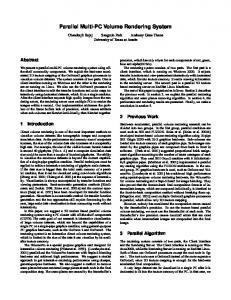
We present results from interactive visualization of two unstructured meshes exceeding respectively 5 million and 2 million tetrahedra, both with 13 field values. We were able to demonstrate realtime data exploration of both full data-sets, allowing for interactive rendering, color manipulation, and probe clipping while sustaining any frame rate desired. Table 1 lists different performance data from the pre-processing of the larger data-set, the“cannister”. Note that the combined preprocessing to construct the compact data structures of the Shell and Solid always took less than 5 minutes on a medium sized PC. All the images shown are rendered using fast but un-aliased OpenGL points (i.e. squares) as the splatting kernel for the bounding spheres. Figure 5 shows separate renderings of the Shell and Solid. Note the missing bottom part inside the Shell due to backface culling. Figure 9 shows renderings with different fixed minimum pixel splat sizes and Figure 7 shows different CSG probes and color transfer functions applied interactively to the cannister dataset. Figure 6 shows the same model rendered with splats derived from different geometric primitives. Clearly the triangles produce the highest resolution models, but vertices and the tetrahedra also lead to relatively good renderings with significantly smaller memory footprints (see Table 1). Figure 8 illustrates the importance of the adaptive CSG culling discussed in the previous section. Without our proposed adaptive rendering along the edge of the CSG probe, disturbing silhouettes from intersecting splats will pop up during interactions with the data-set. Finally Figure 10 shows different CSG cuts of a smaller data-set from a so-called “Taylor impact” simulation. The use of an unbalanced octree, as oppose to an unbalanced quadtree for the Solid, reduced the memory consumption by more than 25% for the cannister data set. In fact this number increases with the number of field values encoded into the data structure. The frame-rates for a fixed resolution improved by approximately the same amount depending on the resolution and extend of volumetric clipping. The average branching factors of the corresponding Solid trees were respectively 2.9 and 5.3. 5
Figure 8: Left: regular (i.e. uniform) rendering of CSG edge with δr = δb = 10 pixels. Note the silhouettes form intersecting splats. Right: our improved adaptive rendering with δr = 10 pixels and δb = 1 pixel. See Algorithm 3 and Section 3.2 for definitions of δr and δb .
long as it’s possible to consistently define attributes like position, radius and normal vectors for the splats that serves as leaf nodes in the bounding-sphere hierarchical tree structures. As mentioned before the tetrahedral meshes we have studied were partitioned on multiple compute nodes due to the tremendous numerical challenges involved in solving the CFD simulations on the mesh. We have already made use of this for the pre-processing, but we are currently working on parallelizing the rendering as well. This will remove the bottleneck involved in condensing very large fragments onto a single rendering node and allow for much higher resolutions for any given frame-rate. We would also like to explore alternative compression schemes for the hierarchical encoding of node attributes in our tree structures. Currently we use simple bit-fixed quantization which is simple to implement and allows for very fast on-the-fly decoding. However variable length encoding like Hauffman-coding [14] could potentially lead to much more compact data structures. As a final remark we would like to stress that we do not claim to have invented the “silver bullet” for visualizing unstructured tetrahedral meshes. In fact the work presented in this paper is not even intended as a replacement to existing visualization techniques of medium sized tetrahedral meshes. Rather it should be seen as a
C ONCLUSIONS AND F UTURE W ORK
We have presented TetSplat, a framework for interactive visualization of very large tetrahedral meshes with multiple field values. The approach is based on point-splatting and CSG culling with guaranteed real-time performance regardless of the size of the input mesh and the available rendering hardware. Though our method was exclusively demonstrated on unstructured tetrahedral meshes the approach easily generalizes to any unstructured solid mesh type as
Figure 10: Different CSG cuts of data-set from a “Taylor impact test” consisting of a metallic cylinder impacting a rigid wall. The data has 2,175,488 tetrahedra with 13 attributes on 385,165 vertices. Solid has 4,395,648 leaf nodes and Shell has 89,344 leaf nodes.
439
Table 1: Table of data from the pre-processing of the cannister data set with 5,378,048 tetrahedra, 974,127 vertices and 3 scalar values pr vertex. Original size of this unstructured tetrahedral mesh is 204Mb. Times are reported in minutes (on a single 1.7GHz PC) and combine derivation of Shell and Solid. “branching” denotes the average branching factor for the corresponding Shell and Solid trees. With 3 field values the sizes of the individual Shell and Solid nodes are respectively 10 and 8 bytes.
Primitives Tetrahedra Vertices Triangles
time 3.1 2.8 4.1
leaf nodes – 154,310 308,608
29 pixels 24.9 fps 19355 splats
Shell total nodes branching – – 229,319 3.0 462,807 2.8
16 pixels 10.5 fps 41038 splats
size (Mb) – 2.4 4.8
leaf nodes 5,378,048 819,817 10,601,792
11 pixels 7.1 fps 66798 splats
Solid total nodes branching 6,628,594 5.3 1,003,607 5.5 13,253,693 5.1
7 pixels 3.5 fps 134620 splats
size (Mb) 55.2 9.7 109.2
1 pixels 2.5 fps 252112 splats
Figure 9: Renderings with different fixed splat pixel sizes. Top row shows the full model and bottom row is a closeup. Frame rates are listed in units per second on a P4 1.7GHz, Radeon 8700.
point-based alternative in situations where real-time rendering for fast inspection of large meshes is of outmost importance. We acknowledged that there may be situations where the tradeoffs related to using point-based rendering as oppose to polygon rendering is just not acceptable. One of the biggest disadvantages of our method is actually that it does not work very well for small meshes since the individual splats will often be visible. This problem could be addressed with a hybrid method where we switch to polygon rendering when the splat-size is large enough to cause aliasing. However it will obviously not be trivial to integrate this idea into our current real-time renderer with CSG clipping. R EFERENCES [1] B. Adams and P. Dutr´e. Interactive boolean operations on surfelbounded solids. In Proc. SIGGRAPH 2003, pages 651–656. ACM, 2003. [2] J. Arvo and D. Kirk. An Introduction to Ray Tracing, chapter A Servey of Ray Tracing Acceleration Techniques. Academic Press, 1989. [3] Mario Botsch and Leif Kobbelt. A robust procedure to eliminate degenerate faces from triangle meshes. In Vision, Modeling, Visualization 2001, pages 283–289. University of Stuttgart, November 2001. [4] P. Cignoni, D. Costanza, C. Montani, C. Rocchini, and R. Scopigno. Simplification of tetrahedral volume with accurate error evaluation. In Proc. Visualization 2000, pages 85–92. IEEE, 2000. [5] P. Cignoni, L. De Floriani, P. Magillo, E. Puppo, and R. Scopigno. Selective refinement queries for volume visualization of unstructured tetrahedral meshes. IEEE Trans. on Visualization and Computer Graphics, 10(1):29–45, 2004. [6] C. Dachsbacher, C. Vogelgang, and M. Stamminger. Sequential point trees. In Proc. SIGGRAPH 2003, pages 657–662. ACM, 2003. [7] J. D. Foley, A. Van Dam, S. K. Feiner, and J. F. Hughes. Computer Graphics (2nd ed. in C): principles and practice. Addison-Wesley Longman Publishing Co. Inc., 1996. [8] S. Fortune. Numerical stability of algorithms for 2d delaunay triangulations. International Journal of Computational Geometry and Applications, 5(1-2):193–213, 1995.
440
[9] T. Funkhouser and C.S´e quin. Adaptive display algorithm for interactive frame rates during visualization of complex virtual environments. In Proc. SIGGRAPH 1993, volume 27, pages 247–254. ACM, 1993. [10] T. Gerstner and R. Pajarola. Topology preserving and controlled topology simplifying multiresolution isosurface extraction. In Proc. Visualization ’00, pages 259–266. IEEE, 2000. [11] A. S. Glassner, editor. Graphics Gems, chapter Triangles. Academic Press, 1990. [12] M. H. Gross and O. G. Staadt. Progressive tetrahedralizations. In Proc. Visualization ’98, pages 397–402. IEEE, 1998. [13] J. P. Grossman and W. Dally. Point sample rendering. In Eurographics Rendering Workshop, pages 181–192. EA, 1998. [14] D. Hauffman. A method for the construction of minimum redundancy codes. In Proc. IRE, volume 40, 1952. [15] D. Laur and P. Hanrahan. Hierarchical splatting: A progressive refinement algorithm for volume rendering. In Proc. SIGGRAPH 1991, pages 285–288. ACM, 1991. [16] M. Levoy and T. Whitted. The use of points as a display primitive. Technical Report TR85-022, Stanford, 1985. [17] S. M. Rubin and T. Whitted. A 3-dimensional representation for fast rendering of complex scenes. In Proc. SIGGRAPH 1980, pages 110– 116. ACM, 1980. [18] S. Rusinkiewicz and M. Levoy. Qsplat: A multiresolution point rendering system for large meshes. In Proc. SIGGRAPH 2000, pages 343–352. ACM, July 2000. [19] J. R. Shewchuk. The geometry junkyard. http://www.ics.uci.edu/ eppstein/junkyard/circumcenter.html. [20] L. Shirman and S. Abi-Ezzi. The cone of normals technique for fast processing of curved patches. In Proc. Eurographics 1993, volume 12, pages 262–272. EA, 1993. [21] I. J. Trotts, B. Hamann, and K. I. Joy. Simplification of tetrahedral meshes with error bounds. IEEE Trans. Visualization and Computer Graphics, 5(3):224–237, 1999. [22] Y. Zhou, B. Chen, and A. Kaufman. Multiresolution tetrahedral framework for visualizing regular volume data. In Proc. Visualization ’97, pages 135–142. IEEE, 1997.