1
Real-Time Widely Distributed Instrumentation Systems William E. Johnston1 and Brian Tierney Ernest Orlando Lawrence Berkeley National Laboratory Berkeley, CA, 94720
Abstract In the future, real-time, on-line instrument systems connected by wide area networks will be the norm for scientific, medical, and similar data generating systems, because the associated human community, the instruments, and the resources required for data processing are increasingly distributed. The modern instrument environment is characterized by steadily increasing quantities and rates of data, together with the remote interaction of the humans and hardware. This environment gives rise to the need for a variety of capabilities: dynamically schedulable resources, easily administered and enforced use-conditions and access control for all elements, systems designed to adapt to varying conditions in the distributed environment, automated approaches to managing the data streams, automated control and guidance systems that facilitate remote (in time, space, and scale) operations, and a myriad of reservation and scheduling capabilities for all of the resources involved. Brokered construction of these systems will probably also be necessary in order to reduce the capital investment needed for instrument systems that only operate with small duty cycles, but which require large storage and computing capacity while operating. When the instrument is connected directly to the network, architectural considerations for systems that deal with real-time distributed data sources include high-speed network based data caches and associated distributed processing for on-line data analysis, real-time cataloguing of the original and processed data based on provided or derived metadata, transparent and distributed security mechanisms that control access to the data and the system elements by a distributed user community, as well as maintaining the internal integrity of the distributed system, and mechanisms for standardized monitoring and management of every component and communication path in order to detect “congestion” of all forms and provide information that allows the distributed system to adapt. This chapter describes some of the architectural and implementation issues based on examples of high performance, real-time, on-line systems that illustrate the above points. The examples include a media-rich, remote collaboration environment, an on-line medical imaging system that collects, processes, and catalogues tens of gigabytes per day in a metropolitan area network, a high data-rate, high volume data collection system, and remote operation based on a semi-autonomous control system. Also discussed are several supporting middleware services, including a distributed-parallel network data cache (whose internal architecture also illustrates many of the points mentioned above), agent-based monitoring and distributed system management, and a public-key cryptography infrastructure based access control system.
1.0 Chapter Outline In this chapter we first provide some rationale for remote, real-time applications. In section 3 we characterize the problems, discussing the nature of remote operation in terms of an example that is “collaboration rich”, followed
1. Author’s address: Lawrence Berkeley National Laboratory, MS 50B-2239, Berkeley, CA 94720. Tel: +1-510-486-5014, fax: +1-510-486-6363,
[email protected], http://www-itg.lbl.gov/~johnston. This document is report LBNL-41000.
Chapter for The Grid: Blueprint for a New Computing Infrastructure. Edited by Ian Foster and Carl Kesselman. Morgan Kaufmann, Pubs.
Real-Time Widely Distributed Instrumentation Systems
2
by a discussion of a system that depends on real-time data cataloguing, an architecture for a very high data rate and volume system, and a control-centered remote system. In section 4 we discuss some of the issues and approaches to providing the infrastructure that is required to support the applications described in section 3. We describe a model architecture, network-based caches, agent-based management and monitoring, policy-based access control systems, and a computational architecture for remote servoing. Finally we acknowledge some of the many contributors to this work, and provide some references for further reading.
2.0 Introduction Useful and robust operation of real-time distributed systems requires many capabilities: • automated management of data streams (cataloguing and storage), • automated and autonomous management of the distributed system components, • semi-autonomous operation of remote instrument systems, • generalized access control, • dynamic scheduling and resource reservation, • application designs that can adapt to congestion in the processing, storage, and communication infrastructure. • mechanisms for brokering dynamic, just-in-time construction of systems. These capabilities will be built on supporting architecture, middleware, and low-level services, such as: • high-speed, network based caches • real-time cataloguing system (asynchronous generation of metadata that builds indexed object archives) • distributed management of distributed access control that supports - distributed system internal integrity - enforcement of resource and data use-conditions - security (confidentiality and protection from malicious behavior) • agent-based systems that provide - autonomous monitoring of all resources (including data) - dynamic analysis of performance - autonomous component management for reliability/survivability - automated resource brokering for dynamic system construction. 2.1 Rationale for distributed real-time applications High-speed data streams result from the operation of many types of on-line instruments and imaging systems, and are a “staple” of modern scientific, health care, and intelligence environments. The advent of shared, widely available, high-speed networks is providing the potential for new approaches to the collection, organization, storage, analysis, and distribution of the large-data-objects that result from such data streams. The result will be to make both the data and its analysis much more readily available. To illustrate this emerging paradigm, we examine several examples from quite different application domains, but which have a number of similar architectural elements. Health care imaging systems illustrate both high data rates and the need for real-time cataloguing. High-volume health care video and image data used for diagnostic purposes — e.g., X-ray CT, MRI, and cardio-angiography — are collected at centralized facilities and, through widely distributed systems, may be stored, managed,
draft chapter for “Building a Computational Grid”, Foster and Kesselman, eds.
Real-Time Widely Distributed Instrumentation Systems
3
accessed, and referenced at locations other than the point of collection (e.g., the hospitals of the referring physicians). In health care imaging systems the importance of remote user access is that the health care professionals at the referring facility (hospitals or clinics frequently remote from the tertiary imaging facility) have ready access to not only the image analyst’s reports, but the original image data as well. Additionally, the importance of providing and managing distributed access to tertiary storage is that laboratory instrumentation environments, hospitals, etc., are frequently not the best place to maintain a large-scale digital storage system. Such systems can have considerable economy of scale in operational aspects, and an affordable, easily accessible, high-bandwidth network can provide location independence for such systems. High energy physics experiments illustrate both very high data rates and volumes that have to be processed and archived in real time, and must be accessible to large scientific collaborations -- typically hundreds of investigators at dozens of institutions around the world. High-bandwidth (20-40 megabytes/s) data handling for analysis of high-energy and nuclear physics data is increasingly likely to have a source of data that is remote from the computational and storage facilities. The output from particle detectors (the instrument) is subjected to several stages of data reduction and analysis. After the initial processing the analysis functions are carried out by dispersed collaborators and facilities. Their analysis is then organized in information systems that may reside on a single storage system or be distributed among several physical systems. Remote microscopy control illustrates the problem of the human always being remote from the controlled system or object of interest. Data is typically collected as images (in the spacial or Fourier domains) that are then analyzed to provide information both for experiment control and analysis. Experiment and instrument control includes object tracking, both in order to keep the object visible (e.g., drift and depth-of-focus compensation) and to observe changes in the object. Some of this information may be fed back to the apparatus that is acting on the object, as in application of electromagnetic fields, thermal gradients, etc. (These are “in-situ” experiments.) In all of these cases the operator is “remote”, since the precision, repetition, or time scale means that humans cannot effectively directly perform the required tasks. The human operators provide the high-level control, such as initially identifying objects of interest, establishing operating set points, defining protocols for the in-situ experiments, etc. By providing automated operation of the low latency low-level control, the human functions can be carried out over wide area as well as local area networks.
3.0 Problem Characterization and Prototypes There are several aspects to real-time management of distributed instrumentation systems involving the operations that they perform and/or the data that they collect. Most broadly stated, these systems involve one or more of: • remote operation of instrument control functions • distributed data collection and management • distributed data analysis and cataloguing Each of these regimes requires a supporting infrastructure of both middleware, and systems and communications services. Some of the required middleware services include:
draft chapter for “Building a Computational Grid”, Foster and Kesselman, eds.
4
Real-Time Widely Distributed Instrumentation Systems
• automated cataloguing and tertiary storage system interfaces (i.e. a digital library system between the instrument and the user) • automated monitoring and management systems for all aspects of the distributed components • policy-based access control systems to support scheduling and resource allocation (e.g. quality-of-service), security, distributed system integrity, and (potentially) automated brokering and system construction • rich media capabilities to support telepresence and collaboration Supporting systems and communications services include • flexible transport mechanisms • reliable and unreliable wide-area multicast • resource reservation and quality-of-service for computing, storage, and communications • security to protect the network-level infrastructure These capabilities are not sufficient, but are a representative collection of necessary services for remotely operated, high-performance data systems. In the next few sections we will illustrate some of the issues that give rise to the need for these services. 3.1 The nature of remote operation Distributed instruments can be remote in space, time, or scale. Remote in space is the typical circumstance for network distributed scientific collaboration, where instruments are located at one facility, principal investigators are located at others, and data processing and storage at yet others. Another common circumstance is that the controlled function is sufficiently remote in scale that direct control is not possible. Many microscopic experiment environments fall into this category. The operation of the Mars Pathfinder mission Rover vehicle provides an example of functional control that is remote in time. (Rover operation was specified a day in advance, and then the actions were uploaded for the following day’s mission which was carried out autonomously.) Each of these scenarios provides circumstances that have to be addressed for remote operation. When the operator is remote from the instrument, as is the case when the instrument is located at a national facility like LBNL’s Advanced Light Source2 and the investigators are located at Universities and laboratories scattered across the country, then several issues result. Multiple media streams are typically required in order to support human interaction (audio and video conferencing and worksurface sharing) and to provide a sense of presence (remote environment monitoring) so that the general environment, including the equipment area, local personnel, etc., can be observed in order to verify general operational status. The experiment itself (e.g. a sample chamber) must typically be visually monitored as a “sanity” check to ensure that the data stream is actually the result of the intended experiment, etc. Finally, the data is shared in real time among several experimenters, and so
2. The Advanced Light Source is a particle accelerator that is specialized to produce high intensity, highly monochromatic X-rays. Such electromagnetic radiation provides important analytical capabilities for material and biological sciences.
draft chapter for “Building a Computational Grid”, Foster and Kesselman, eds.
Real-Time Widely Distributed Instrumentation Systems
5
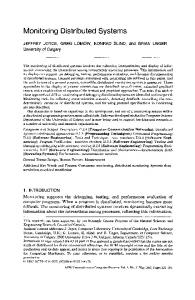
more other data streams are required for the on-line analysis and control. (See Figure 1, [Agarwal97], [Agarwal95], and [Sachs96] .)
Experimenter at Univ. of Wisconsin
2200 miles 125 ms packet roundtrip
Wide Area Network Advanced Light Source, Lawrence Berkeley National Laboratory
Figure 1
Beamline 7 of the ALS is a media-rich remote experiment environment: many media streams are required to provide telepresence and data sharing in complex remote instrumentation.
Multiple collaborators, each of whom need to see the instrument output in real-time and potentially control the instrument, require synchronized and reliable access to the data and control. The shared control panels shown in Figure 1 illustrate such a capability that is based on reliable multicast protocols. The model for real-time capture and cataloguing is that a data source generates units of data that have associated auxiliary information. As the data is processed in real-time, the “units” can be identified as such, and the appropriate associated data can also be identified.
draft chapter for “Building a Computational Grid”, Foster and Kesselman, eds.
6
Real-Time Widely Distributed Instrumentation Systems
A key issue with “identification” of a unit of data is to know when the unit has been completely received so that cataloguing and processing to create a data-object can commence. This identification can take the form of explicit in-band markers in the data stream, or out-of-band notification that all of the data of one unit has been sent, or the identification could be implicit, such as a data unit being defined by a timing mechanism (e.g., one data unit is whatever is received in some specified period of time) or by a quantity mechanism (e.g., one data unit is a fixed quantity of data). Likewise, the acquisition of associated information (metadata pre-cursors) can be via explicit in-band or out-of-band separate data units, or implicit (e.g., the timestamp of a data unit whose boundary is defined by a point in time). When the scale of the operations is very different than human scale, then remote operation must typically involve some machine intelligence. The automated operations will analyze the sensor data in real-time and adapt the progress of the experiment depending on the results of analysis. The human function is to set up the experiment, identify the object of interest in the experiment environment, etc., but the actual operation cannot be in human hands as noted above. This same approach can also be the key to remote operation of experiments. That is, a network of unpredictable or high latency (the norm in wide-area IP networks) cannot be used to provide fine-grained, real-time control (e.g. in a closed loop servo system where the operating functions are at one end of the network and the data analysis that provide the feedback is at the other end). In this situation it is again the case that incorporating machine intelligence into the experiment control system, and performing monitoring and data analysis remotely is an architecture that addresses this problem. These issues are illuminated with specific examples in the next several sections, as are some approaches to addressing the issues. 3.2 Real-time Data Cataloguing: An on-line cardio-angiography3 system In many environments the key aspect of real-time data is the immediate and automated processing necessary to organize and catalogue the data and make it available to remote sites. This example illustrates a scenario where data is generated in large volumes and with high throughput, and especially in a distributed environment where the people generating the data are geographically separated from the people cataloguing or using the data, there are several important considerations for managing this type of instrument generated data: • automatic generation of at least minimal metadata; • automatic cataloguing of the data and the metadata as the data is received (or as close to real time as possible); • transparent management of tertiary storage systems where the original data is archived; • facilitation of co-operative research by providing specified users at local and remote sites immediate as well as long term access to the data; • incorporation of the data into other databases or documents.
3. Cardio-angiography imaging involves a two plane, X-ray video imaging system that produces from several to tens of minutes of digital video sequences for each patient study. The digital video is organized as tens of data-objects, each of which are of the order of 100 megabytes.
draft chapter for “Building a Computational Grid”, Foster and Kesselman, eds.
Real-Time Widely Distributed Instrumentation Systems
7
For the on-line cardio-angiography system (a remote medical imaging system), a real-time digital library system collects data from the instrument and automatically processes, catalogues, and archives each data unit together with the derived data and metadata, with the result being a Web-based object representing each data set. This automatic system operates 10 hours/day, 5-6 days/week with data rates of about 30 Mbits/sec during the data collection phase (about 20 minutes/hour). (See Figure 2.) Kaiser San Francisco Hospital Cardiac Catheterization Lab (digital video capture) LBNL WALDO server and DPSS for data processing, cataloguing, and storage
Kaiser Oakland Hospital (physicians and databases)
Lawrence Berkeley National Laboratory and Kaiser Permanente On-line Health Care Imaging Experiment
Figure 2
to the MAGIC testbed
Kaiser Division of Research NTON network testbed
San Francisco Bay Area
A distributed health care imaging application. (See [DIGLIB].)
WALDO (“wide-area large-data-objects”) is a real-time digital library system that uses federated textual and URL linked metadata to represent the characteristics of large data sets. (see Figure 3 and [DIGLIB].) Automatic cataloguing of incoming data is accomplished by extracting associated metadata and converting it into text records, by generating auxiliary metadata and derived data, and by combining these into Web-based objects that include persistent references to the original data-components. Tertiary storage management for the data-components (i.e., the original datasets) is accomplished by using the remote program execution capability of Web servers to manage the data on a mass storage system. For subsequent use, the data-components may be staged to a local disk and then returned as usual via the Web browser, or, as is the case of high performance applications, moved to a high speed cache for direct access by the specialized applications. The location of the data-components on tertiary storage, how to access them, and other descriptive material, are all part of the object definition. The creation of object definitions, the inclusion of “standardized” derived-data-objects as part of the
draft chapter for “Building a Computational Grid”, Foster and Kesselman, eds.
8
Real-Time Widely Distributed Instrumentation Systems
metadata, and the use of typed links in the object definition, are intended to provide a general framework for dealing with many different types of data, including, for example, abstract instrument data and multi-component multimedia programs. WALDO uses an object-oriented approach to provide for capture, storage, catalogue, retrieval, and management of large-data-objects and their associated metadata. The architecture includes a collection of widely distributed services to provide flexibility in managing storage resources, reliability and integrity of access, and high performance access, all in an open environment where the use-conditions for resources and stored information are guaranteed through the use of a strong, but decentralized, security architecture. The WALDO model for the capabilities of a distributed, real-time cataloguing, large-data-object system includes the following elements: • real-time cataloguing of extensible, linked, multi-component data-objects that can be asynchronously generated by remote, on-line data sources • class-based methods for management of the large-data-objects • on-line metadata, with cacheable off-line components • representation of the object components as Web-accessible elements • explicit association of access methods with the data components • flexible curator / collection-owner management of collections of data-objects, including “any-time” management of the collection organization and object metadata • globally unique and persistent naming of the objects and their various components via URLs and URNs • strong access control at the level of individual object components based on use-condition certificates managed by the data owner • high-performance application access to the data-components • flexible and extensible approaches to searching. WALDO Software Architecture Figure 3 illustrates the data flow and overall organization of the WALDO architecture. It also indicates the central role of high-speed caches which are used both for initial data collection, and to provide subsequent high-speed access by applications. The basic elements of the architecture (referring to Figure 3) include: • data collection systems and the instrument-network interfaces (1) • high-speed, network-based cache storage for receiving data, for providing intermediate storage for processing, and for high-speed application access (2) • transparent tertiary storage (“mass storage”) management for the data-components (8) • processing mechanisms for various sorts of data analysis and derived data generation (3) • data management that provides for the automatic cataloguing and metadata generation that produces the large-data-object definitions (4) • data access interfaces, including application-oriented interfaces (5) • curator interfaces for managing both the metadata and the LDO collection organization (9) • user access interfaces for all relevant aspects of the data (applications, data, and metadata) (10) • flexible mechanisms for providing various searching strategies (6) • transparent security that provides strong access control for the data components based on data-owner policies (7)
draft chapter for “Building a Computational Grid”, Foster and Kesselman, eds.
Real-Time Widely Distributed Instrumentation Systems
producer
object management
(capture, catalogue)
(persistence, metadata mg’mt, storage mg’mt)
me
t ad ata
LDO “object” description generation (4)
DPSS (2) +
high speed data cache for incoming data +
generate: • object template • metadata • derived representations manage initial archival storage
consumer
Web browser +
Web server +
Processing (3) +
9
+ + +
+
(5)
LDO access methods search engine management cache/MSS management (8) some LDO data-components
data-user interface (10) curator interface (9)
search engine (6) (5) Application +
access control (7)
cache-based or Web-based access to LDO components
Data Source (1) + + +
collection buffering network transport
Figure 3
MSS +
tertiary storage archiving of large-data-components
local storage +
WALDO Web server based LDO component storage
DPSS (2) +
cache for high speed application access to data
public-key infrastructure use-condition certificates
The distributed Large-Data-Object overall architecture and data flow.
These elements are all provided with flexible, location-independent interfaces so that they can be freely (transparently) moved around the network as required for operational or other logistical convenience. This general model has been used in several data-intensive computing applications, however it raises a number of issues. The distributed cache is an important component, but one that requires distributed management and distributed security. The incorporation of a digital library-like function is an important consideration, but such automatic cataloguing in the face of human error in the operation of the instrument (and the resulting errors in the metadata and cataloguing) require human curation of the library. Access control is a critical aspect when sensitive or confidential data are involved, and the management of the access control must also be distributed to the various principals. Approaches to several of these issues are discussed below.
draft chapter for “Building a Computational Grid”, Foster and Kesselman, eds.
10
Real-Time Widely Distributed Instrumentation Systems
3.3 High Data Rate Systems: Particle accelerator detectors High Energy and Nuclear Physics experiments consists of detector systems at particle accelerators. Modern detectors like STAR4 will generate 20-40 megabytes/sec of data that has to be processed in two phases - data collection and event reconstruction (phase 1) and physics analysis (phase 2). (See [Greiman] and [Johnston97b].) In phase 1 of physics experiment data analysis, a detector puts out a steady state high data-rate stream (20-40 On-line megabytes/s for STAR). Traditionally, Event Data these data are archived and a first level Storage (DPSS) of processing is performed at the Detector Environment experiment site. The resulting second-level data are also archived and multiplex ATM A approximately to LAN then used for the subsequent physics the T reconstruction M analysis. The data is thus archived at the platform level W experiment site in “medium” sized A Detector Local Data N tertiary storage systems. This approach Buffer has disadvantages in that large mass storage systems are one of the few Off-line computing technologies that continue to Event Reconstruction Archive exhibit significant economies of scale, and (mass storage High-Performance and therefore central sites like the large systems exhibit Analysis Cluster significant economies of mass storage systems at NERSC5 load-balancing as required scale) here rather that at head-end reconstruction data flow remain an important architectural component in high data-volume Figure 4a Distributed physics data handling, Phase 1 data systems. However, the potential flows. problems of the network access to large-scale storage systems must be overcome with network-based caching. In a computational grid environment the “medium” sized tertiary systems at experiment sites can be replaced by a distributed cache consisting of a high-speed, high-capacity network-based cache and very large tertiary systems at dedicated storage sites. The Distributed-Parallel Storage System (DPSS -- described below) can serve as the cache for all stages of data manipulation. The DPSS provides a scalable, dynamically configurable, high-performance, and highly distributed
4. The STAR detector (Solenoidal Tracker at the Relativistic Heavy Ion Collider at the Brookhaven National Laboratory) will search for signatures of quark-gluon plasma (QGP) formation and investigate the behavior of strongly interacting matter at high energy density. The emphasis will be the correlation of many observables on an event-by-event basis. In the absence of definitive signatures for the QGP, it is imperative that such correlations be used to identify special events and possible signatures. This requires a flexible detection system that can simultaneously measure many experimental observables. See http://www.rhic.bnl.gov/STAR/star.html . 5. The National Energy Research Scientific Computing Center provides high-performance computing services to researchers supported by the US Department of Energy Office of Energy Research. NERSC is located at the Ernest Orlando Lawrence Berkeley National Laboratory. See http://www.nersc.gov .
draft chapter for “Building a Computational Grid”, Foster and Kesselman, eds.
Real-Time Widely Distributed Instrumentation Systems
11
storage system that is usually used as a (relatively long-term) cache of data. It is typically used to collect data from on-line instruments and then supply that data to analysis applications, or to high data-rate visualization applications (as in the case of the MAGIC, wide-area gigabit testbed where the DPSS was originally developed -see [Lau], [DPSS], and [MAGIC]). The system is also being used in satellite image processing systems and for the distributed, on-line, high data-rate health care imaging systems described above. The architecture illustrated in Figure 4a and Figure 4b supports distributed computational systems doing the phase 1 data processing in real time. The real-time processing of this data potentially also supports two capabilities. First, it can provide auxiliary information to assist in the organization of data as it is transferred to tertiary storage (the STAR experiment will generate about 1.7 terabytes/day), and second, it can provide feedback to the instrument operators about the functioning of the accelerator - detector system and the progress of the experiment, so that changes and corrections may be made.
ATM Net
Remote Analysts Local Event caching on (DPSS)
Local Event caching on (DPSS)
On-line Event Data Storage (DPSS)
A T M W A N
Remote Analysts Reconstruction and High-Performance Analysis Cluster
Off-line Event Archive
In the phase 2 processing (interactive analysis data flow analysis), the architecture enables an efficient implementation of the Figure 4b Distributed physics data handling, Phase 2 data second-level analysis of the data. This flows. involves using a high-speed cache like the DPSS as a large “window” on the tape-based data in the tertiary storage system in order to support the use of both local and remote computational resources. This is illustrated in Figure 4b. Prototype version of this architecture have been successfully tested, and this is described in [Johnston97b]. The issues raised in this environment include the use of distributed caches, the organization of the cache, the various interfaces to the cache, the management of the movement of data to and from the tertiary storage systems, and management of the cache components in a wide area network.
draft chapter for “Building a Computational Grid”, Foster and Kesselman, eds.
12
Real-Time Widely Distributed Instrumentation Systems
3.4 Control Centered Systems: In-situ electron microscopy An evolutionary step in multimedia systems is for them to provide the computational framework to extract meaningful information from images and video sequences in real-time, and then use this information to manipulate experiments, or perform other operations, based on the information content of the images. This real-time analysis enables semi-autonomous, remote control by enabling servoing based on the image content. One such application of this approach is a system for remote operation of in-situ microscopy. A testbed for this approach is a 1.5 million electron volt (MeV) transmission electron microscope (HVEM), shown in Figure 5, that is operated by the National Center for Electron Microscopy6. In-situ microscopy refers to a class of scientific experiments in which a specimen is excited by external stimuli and the response must either be observed or controlled. The stimuli could, e.g., be The high voltage electron in the form of temperature variation or stress in the sample Figure 5 microscope at NCEM environment. The interaction of the external stimuli and specimen can result in sample drift, shape deformation, changes in object localization, changes in focus, or simply anomalous specimen responses to normal operating conditions. Currently, during the in-situ experiments the operator must make constant adjustments to the instrument to maintain depth of focus and compensate for various drifts. These are labor intensive and error prone tasks -requiring a high bandwidth video link to the operator -- that are nearly impossible to do in wide area networks due to limited network bandwidth. Considering a specific example, there is a class of in-situ electron microscopy experiments that require dynamic interaction with the specimen under observation as it is excited with external stimuli, i.e., temperature variation, EM field variation, etc. The dynamic operations include control of the sample’s position and orientation under the electron beam, the illumination conditions and focus, etc. Remote control via wide area networks like the Internet that do not offer real time data and command delivery guarantees are not practical for the finely tuned adjustments that dynamic studies require. Enabling remote control of dynamic experiments involves separating the basic human interaction of establishing control system parameters like gross positioning, identifying objects of interest, etc. (that do not require low latency interaction) from the control servoing that performs operations like auto-focus, object detection, continuous fine positioning due to thermal drift, etc., that do require low latency interaction. The human interaction operations, together with the supporting human communication involving video and audio teleconferencing, can easily be performed in a wide area network environment ([Floyd], [McCanne]).
6. The National Center for Electron Microscopy is a DOE User Facility providing the U.S. electron microscopy community with advanced instrumentation for electron-optical characterization of materials. The NCEM is part of the Materials Science Division of the Ernest Orlando Lawrence Berkeley National Laboratory. See http://ncem.lbl.gov .
draft chapter for “Building a Computational Grid”, Foster and Kesselman, eds.
Real-Time Widely Distributed Instrumentation Systems
13
The dynamic control operations must occur in a much more controlled environment where the control operation and the monitored response to the control or stimuli have to be coupled by low latency communication that is not possible in wide area networks. So, the approach is that dynamic remote control applications involve automated control operations performed near the instrument in order to eliminate the wide area network real-time delivery requirement. This approach requires determining the type of servo loops needed to enable remote operation and collaboration, and the implementation of a control architecture. The basic aspect of the architecture is a partitioning that separates the low frequency servo loop functions that enables direct human interaction performed over the wide area network, and those functions that require low latency control are performed locally using automated techniques (see Figure 6). The approach hides the latencies in the wide area network and permits effective remote operation. The result is telepresence that provides the illusion of close geographical proximity for in-situ studies. Using this approach, the testbed 1.5 MeV transmission electron microscope can now be used on-line via the global Internet. In the case of image-based instrumentation, the automated compressed video for control may be accomplished monitoring video to by using computer vision network algorithms that permit interface microscope instrumentation adjustments to be made automatically in response to information Video stream human extracted from the video signal analysis interaction, video gateway (e.g. for auto e.g. establish imagin generated by the microscope focus and shape “set point” imaging system. Thus, by detection) information stage for “coarse” relieving the operator of having drive control to do the dynamic adjustment server for Remote of the experimental setup, operating Control remote collaboration and control Environment equipment remote operation of the in-situ studies over a wide area network are made possible. Local Environment The computational vision techniques that support remote unpredictable in-situ microscopy applications WAN include: 1) image compression, Remote, semi-autonomous, dynamic experiment operation 2) autofocusing, 3) self Figure 6 architecture calibration, 4) object detection, 5) tracking using either high level or low level features, and 6) servo-loop control mechanisms. (See [Parvin95a] and [Parvin95b]). The image content analysis that provides the information that is fed back to the control system is automated and performed in the environment local to the instrument. That is, the computers that acquire and analyze the video
draft chapter for “Building a Computational Grid”, Foster and Kesselman, eds.
Real-Time Widely Distributed Instrumentation Systems
14
images and then communicate with the control system are all connected by fast local area networks. The set points that initialize the servo loops - the selection of objects-of-interest, the parameters of external forcing functions, etc., as well as the monitoring of the experiment, may be carried out in a wide-area network environment. The microscope and experiment control interface, and a typical image, together with the results of video content analysis for shape and drift velocity, are illustrated in Figure 7. The main issues that are raised by this sort of remote operation are the servoing architecture and the algorithms used for information extraction and control. (See [Parvin97].) 3.5 Summary The examples presented in this section (a media-rich instrument Figure 7 Remote in-situ experiment interface for the NCEM control environment, a health care HVEM microscope. imaging system doing autonomous data collection and cataloguing, a high data volume physics experiment environment, and a semi-autonomous control system) illustrate several aspects of remote operation, and expose some of the capabilities that will be needed to support routine construction and use of these types of systems in the future. In summary, the on-line angiography system requires automated management of data streams, the use of a network cache, automatic cataloguing, and distributed access control. These, in turn, require semi-autonomous monitoring, quality-of-service guarantee mechanisms in the network and in the processing and storage systems. The STAR detector scenario uses a widely distributed configuration of the network cache and distributed management of computational resources and data. The shared interface example of the ALS Beamline 7 requires reliable multicast in wide-are networks and rich media management mechanisms. All of the examples require distributed management of system resources and distributed management of distributed access control, both for security and for the “distributed enterprise” management of users and resources. In the next section we examine some approaches to providing these capabilities. In addition, most of the scenarios would potentially benefit from bandwidth adaptive interface features, and the Beamline 7 and microscopy scenarios are candidates for dynamic system construction with brokered resources to support their transient needs for significant computational resources. These desired capabilities are noted as potentially important, however are not addressed in our current systems.
draft chapter for “Building a Computational Grid”, Foster and Kesselman, eds.
Real-Time Widely Distributed Instrumentation Systems
15
4.0 Issues, Capabilities, and Future Directions In this section we describe some of the architectural and middleware approaches that are proving useful, and sometimes critical, in implementing high-performance distributed instrumentation and data systems. 4.1 A Model Architecture for Data Intensive Environments One model that has proven successful in the automated cataloguing and high data-rate application domains is that of using a high-speed distributed cache as a common element for all of the sources and sinks of data involved in high-performance data systems.
For the various data sources and sinks, the cache, which is itself a complex and widely distributed system, provides: • a standardized approach for high data-rate interfaces;
initial data processing cache interface
analysis applications cache interface
high-speed, distributed random access cache
cache interface instrument (e.g., detector)
object management
cache interface
This cache-based approach provides standard interfaces to a large, application-oriented, distributed, on-line, transient storage system: Each data source deposits its data in the cache, and each data consumer takes data from the cache, usually writing the processed data back to the cache. In almost every case there is also a tertiary storage system manager that migrates data to and from the cache at various stages of processing. (See Figure 8.)
object archiving and management
archive data mover MSS interface
tertiary storage system (e.g., HPSS)
• an “impedance” matching function (e.g., between the coarse-grained Figure 8 The Data Handling Model nature of parallel tape drives in the tertiary storage system and the fine-grained access of hundreds of applications); • flexible management of on-line storage resources to support initial caching of data, processing, and interfacing to tertiary storage. Depending on the size of the cache relative to the objects of interest, the tertiary storage system management (object manager + archive data mover of Figure 8) may only involve moving partial objects to the cache; that is, the cache is a moving window for the off-line object/data set. The application interface to the cache can support a variety of I/O semantics, including Unix disk I/O semantics (i.e., upon posting a read, the available data is returned; requests for data in the data set but not yet migrated to cache cause the application-level read to block until the data is migrated from tape to cache). Generally, the cache storage configuration is large compared to the available disks of a typical computing environment, and very large compared to any single disk (e.g., hundreds of gigabytes).
draft chapter for “Building a Computational Grid”, Foster and Kesselman, eds.
16
Real-Time Widely Distributed Instrumentation Systems
4.2 Network-based caches The Distributed-Parallel Storage System (DPSS) serves several roles in high-performance, data-intensive computing environments. This application-oriented cache provides a standard interface for high-speed data access, and provides the functionality of a single very large, random access, block-oriented I/O device (i.e., a “virtual disk”). It provides high capacity (we anticipate a terabyte sized system for physics data) and serves to isolate the application from the tertiary storage system. Many large data sets can be logically present in the cache by virtue of the block index maps being loaded even if the data is not yet available. In this way processing can begin as soon as the first data has been migrated from tertiary storage. Generally speaking, the DPSS can serve as an application cache for any number of high-speed data sources (instruments, multiple mass storage systems, etc.). The naming issue (e.g., resolving independent name space conflicts) is handled elsewhere. For example, in the on-line health care imaging system mentioned above, the name space issue is addressed by having all of the data represented by Web-based objects which are managed by the Wide Area Large Data Object management architecture (WALDO) [DIGLIB]. At the minimum WALDO provides globally unique naming and serves as a mechanism for collecting different sources of information about the data. The Web object system can also provides a uniform user (or application) front-end for managing the data components (e.g., migration to and from different mass storage systems) and it manages object use-conditions (PKI access control - see [Johnston97a]). The DPSS provides several important and unique capabilities for the distributed architecture. The system provides application-specific interfaces to an extremely large space of logical blocks (16-byte indices); the DPSS may be dynamically configured by aggregating workstations and disks from all over the network (this is routinely done in the MAGIC testbed [MAGIC], and will in the future be mediated by the agent-based management system); it offers the ability to build large, high-performance storage systems from inexpensive commodity components; and it offers the ability to increase performance by increasing the number of parallel DPSS servers. A cache management policy module operates on a per-data set basis to provide block aging and replacement when the cache is serving as a front-end for tertiary storage. The high performance of the DPSS -- about 10 megabytes/sec of data delivered to the user application per disk server -- is obtained through parallel operation of independent, network-based components. Flexible resource management -- dynamically adding and deleting storage elements, partitioning the available storage, etc. -- is provided by design, as are high availability and strongly bound security contexts. The scalable nature of the system is provided by many of the same design features that provide the flexible resource management (that provides the capability to aggregate dispersed and independently owned storage resources into a single cache). When data sets are identified by the object manager (e.g. as in Figure 8) and are requested from tertiary storage, the logical-to-physical block maps become immediately available. The data mover operates asynchronously, and if an application “read” requests a block that has not yet been loaded, then the application is notified (e.g., the read operation blocks). At this point the application can wait or request information on available blocks in order to continue processing. While the basic interface provides for requesting lists of named logical blocks, many applications use file I/O semantics, and these are provided in the DPSS client-side interface library. The internal architecture of the DPSS is illustrated in Figure 9.
draft chapter for “Building a Computational Grid”, Foster and Kesselman, eds.
Real-Time Widely Distributed Instrumentation Systems
17
.
Agent-based management of storage server and network state vis a vis applications
Application (client)
security context - 2 Disk Servers + +
(data use conditions) data requests
block storage block-level access control mem buf
security context - 1 returned data stream
(system integrity & physical resources)
physical block requests
DPSS Master Resource Manager + +
Application data access methods
(“third-party” transfers directly from the storage servers to the application)
logical block requests
allocate disk resources server/disk resource access control
+ + + +
(data structure to logical block-id mappings - e.g., JPEG video multi-res image pyramids Unix file i/o XDR
DPSS API (client-side library)
Data Set Manager Request Manager +
Agent-based management of redundant Masters
Figure 9
+
logical to physical name translation cache management
+ + +
user security context establishment data set access control metadata
Agent-based management of dataset metadata - locations, state, etc.
Distributed-Parallel Storage System Architecture
Typical DPSS implementations consist of several low-cost workstations, each with several disk controllers, and several disks on each controller. A three-server DPSS can thus provide transparent parallel access to 20-30 disks. The data layout on the disks is completely up to the application, and the usual strategy for sequential reading applications is to write the data “round-robin” (stripe across servers), otherwise the most common strategy is to determine the physical block locations randomly when they are written. (Our experience has shown that with the high degree of parallelism provided at the block level when a DPSS is configured from, say, 30 disks spread across three servers, that random placement of blocks provides nearly optimal access time for a wide range of read patterns.)
draft chapter for “Building a Computational Grid”, Foster and Kesselman, eds.
Real-Time Widely Distributed Instrumentation Systems
18
Directions In order for such distributed caches to provide significant value to the remote operation and computational grid environments, several issues are addressed by the DPSS, and some remain to be addressed. For example: ♦ Dynamic reconfiguration of DPSS (needs to be agent managed)
• adding and deleting servers and storage resources during operation ♦ Replication for reliability and performance (needs to be agent managed)
• data replication • name translation and disk servers may be replicated ♦ Data block request semantics to support application data prediction
• prioritized request lists • new request cancels currently unsatisfied (flushes disk read and network write queues, but not memory cache) ♦ Application access semantics
• DPSS logical block model is supplemented by data type-specific access methods • a large block index space allows some encoding of some application information (e.g. long., lat., and elevation for TerraVision tiled image data) • incoming blocks from the many servers are placed directly into a client-side / application buffer, whence they are transformed to application data structures, and the application is notified that the data can be used blocking and poling are implemented in client-side libraries ♦ Data layout issues
• writing mechanism provides complete freedom of data layout, however experience has shown that random placement when using a high degree of disk-level parallelism provides a significant fraction of optimal layout latency ♦ Support for per-dataset cache strategies provide storage system partitioning ♦ Coherency of client-side cache when doing block write-after-read is not currently provided, and will probably
be a broker and agent function 4.3 Agent-Based Management and Monitoring The combination of generalized, autonomous management of distributed components and accurate monitoring of all aspects of the environment in which data moves, has turned out to be a critical aspect of the debugging, evaluation, adaptation, and management of widely distributed, high data-rate applications. In widely distributed systems, the issue is that when you observe that something has gone wrong it is generally too late to react - in fact, you frequently can’t even tell what is wrong, because • the problem depends on a history of events • you can’t get at the needed information any more • it will take too long to ask and answer all of the required questions An agent-based approach for analysis of the operation of distributed applications in high-speed wide-area networks can be used to monitor and identify all of the factors that affect performance, and to isolate the problems arising from individual hardware and software components. Agents can not only provide standardized access to comprehensive monitoring, but can perform tasks such as keeping a state history in order to answer the question
draft chapter for “Building a Computational Grid”, Foster and Kesselman, eds.
Real-Time Widely Distributed Instrumentation Systems
19
“how did we get here?” Active analysis of operational patterns (e.g. pattern analysis of event-based lifeline traces) will lead to adapting behavior / configuration to avoid or correct problems. Monitoring One successful monitoring methodology involves recording every event of potential significance together with precision timestamps, and then correlating events on the basis of the logged information. This allows constructing a comprehensive view of the overall operation, under realistic operating conditions, revealing the behavior of all the elements of the application-to-application communications path in order to determine exactly what is happening within complex distributed systems. This approach has been used in the DPSS distributed storage system and its client applications. As data requests flow through the system, timestamps and log records are generated at every critical point. Network and operating system monitoring tools are used to log additional events of interest using a common format. This monitoring functionality is designed to facilitate performance tuning, distributed application performance research, the characterization of distributed algorithms, and the management of functioning systems (by providing the input that allows adaptation to changes in operating conditions). The approach allows measuring network performance in a manner that is a much better “real-world” test than, e.g., ttcp, et al, and allows us to accurately measure the dynamic throughput and latency characteristics of our distributed application code -- “top-to-bottom” and “end-to-end”. (See [Johnston97b].) This sort of detailed monitoring is also a practical tool for system-level problem analysis, as has been demonstrated in the analysis of a TCP over ATM problem that was uncovered while developing the monitoring methodology in the ARPA-funded MAGIC gigabit testbed (a large-scale, high-speed, ATM network). See [Tierney]. The high-level motivation for this work is two-fold. First, when developing high-speed network-based distributed services, one often observes unexpectedly low network throughput and/or high latency. The reason for the poor performance is frequently not obvious. The bottlenecks can be (and have been) in any of the components: the applications, the operating systems, the device drivers, the network adapters on either the sending or receiving host (or both), the network switches and routers, and so on. It is difficult to track down performance problem because of the complex interaction between the many distributed system components, and the fact that problems in one place may be most apparent somewhere else. A precision and comprehensive monitoring and event analysis methodology is an invaluable tool for diagnosing such problems. Second, such monitoring is one aspect of an approach to building predictable, high-speed components that can be used as building blocks for high-performance applications, rather than having to “tune” the applications top-to-bottom as is all too common today. Continuous and comprehensive monitoring can provide the basis of adapting distributed system behavior to “congestion” in processing, storage, and communication elements. Agent-Based Management of Widely Distributed Systems If comprehensive monitoring is the key to diagnosis, agent-based management may be the key to keeping widely distributed systems running reliably. In one prototype system (see [Where]) “agents” are • autonomous • adaptable
draft chapter for “Building a Computational Grid”, Foster and Kesselman, eds.
Real-Time Widely Distributed Instrumentation Systems
20
• • • • • •
monitors managers information aggregates KQML based information filters implemented in Java constantly communicating with peers and resources
Initial experimentation with such agents in the Distributed-Parallel Storage System (see Figure 10) indicates the 1 Data Curator 1
2
client agent
Monitor Interface
Client Application
dataset agent
Data Curator 2
dataset broker
DPSS broker
dataset agent
1
2
1 DPSS Master WHERE DPSS agent WH
WHMaster DPSS Master DPSS server DPSS server DPSS server DPSS server DPSS DPSS DPSS server serverDPSSserverDPSS 1 WHERE WHERE WHERE server server agent WH agent WHER agent WH 1 1 E agent WHER WH WH E agent
Figure 10
Other caches
11
= distributed system management
2 = data state management
An agent-based monitoring architecture that addresses adaptive operation, reliability/survivability, and dynamically updated metadata for data repositories.
potential for: ♦ Structured access to current and historical information regarding the state of the DPSS components ♦ Reliability - by keeping track of all components within the system and restarts any component that has crashed,
including one of the other agents (addresses fault tolerance) • “associated” agents communicate with each other using IP multicast
draft chapter for “Building a Computational Grid”, Foster and Kesselman, eds.
Real-Time Widely Distributed Instrumentation Systems
21
♦ Automatic reconfiguration - when new components are added, such as a new disk server, the agents do not
have to be reconfigured - an agent is started on the new host, and it will inform all other agents about itself and the new server • brokers and agents may discover interesting new agents via a dynamic directory protocol like SDR or by the support of reliable multicast protocols that provide inter-agent communication, whence the new agent - and resource that it represents - is added to the configuration ♦ Information management - broker agents manage information from a collection of monitor agents (usually on
behalf of a user client) and provide an integrated view for applications such as the graphical status interface illustrated in Figure 11. • for data set state management - agents manage dataset metadata (dynamic state, alternate locations, tertiary location) at each storage system + brokers provide an integrated view of the data over several storage systems • for dynamic configuration and application adaptation - agents continuously monitor state of all network interfaces and data paths + brokers analyze this information on behalf of a client to determine which DPSS has the best network connectivity - agents monitor the load of each DPSS disk server + broker can analyze to decide which servers to use when data is replicated (addresses high availability) ♦ User representation - brokers can perform actions on behalf of a user
• e.g., if a data set is not currently loaded onto a DPSS (which is typically used as a cache), the broker can cause the dataset to be loaded from tertiary storage ♦ System administration - a broker/agent architecture allows the system administrators to separate mechanism
from policy • agent rule-based operation can be used to determine what policies are be enforced while remaining separate from the actual mechanism used to implement these policies ♦ Flexible functionality - new agent methods can be added at any time
• e.g., the brokers have an algorithm for determining which DPSS configuration to use based on a set of parameters that include network bandwidth, latency and disk server load - this algorithm can be modified “on the fly” by loading new methods into the agents • related agents are part of the same security context, and new code/methods presented to the agents is cryptographically signed for origin verification and integrity Prototype implementation Using a prototype of such an agent architecture in the MAGIC testbed, an application uses aggregated information from a broker to present an adaptive and dynamic view of the system: data throughput, server state, and dataset metadata as reported by the agents. Self configuring user interfaces (e.g. as in Figure 11) can be built dynamically, based on a broker agent collecting and organizing classes of information from the relevant set of monitor agents.
draft chapter for “Building a Computational Grid”, Foster and Kesselman, eds.
disk cache server behavior Figure 11
current network configuration
Real-Time Widely Distributed Instrumentation Systems
22
Prototype automatically generated DPSS monitor interface (a Java applet) for brokers aggregating information from DPSS system-state and dataset-state monitoring agents (corresponding to the emphasized elements in the previous figure)
4.4 Policy-Based Access Control in Widely Distributed Environments Widely distributed systems and collaborative environments that involve • multi-user instruments at national facilities • widely distributed supercomputers and large-scale storage systems • data sharing in restricted collaborations • network-based multimedia collaboration channels
draft chapter for “Building a Computational Grid”, Foster and Kesselman, eds.
Real-Time Widely Distributed Instrumentation Systems
23
give rise to a range of requirement for distributed access control. Among other things, for example, administration of such resources as network quality-of-service will need to be handled by an automated authorization infrastructure so that management of both resource availability and allocation, as well as subsequent enforcement of use-conditions, can be done automatically and without recourse to a central or single authority. In all of these scenarios, the resource (data, instrument, computational and storage capacity, communication channel) has multiple stakeholders (typically the intellectual principals and policy makers), and each stakeholder will impose use-conditions on the resource. All of the use-conditions must be met simultaneously in order to satisfy the requirements for access. This model is common in society, and is illustrated in Figure 12. Use-conditions are Imposed by Stakeholders Stakeholders provide and maintain and use-conditions
DOE-HQ LBNL
Memo exclude “bad” countries Memo include all LBNL staff and guests
ALS
ALS Medical Beamline*
Group PI access control
Memo must be group member
Attribute certifiers trusted by the stakeholders Passport agency
good country
LBNL Personnel Dept.
LBNL employee or guest
XYZ State University
X-ray 101
U.C. Human Use Committee
approved protocol
ALS Medical Beamline group PI
Medical R&D group
UC
Memo must have X-ray safety training Memo must have approved protocol
Users have Attributes that Match the Use-conditions
access request *
hypothetical
Figure 12
Access is Granted after Matching Use-conditions and Attributes
Societal Access Control Model
Further, it is common that scientific collaborations are diffuse, with the principals and stakeholders being geographically distributed and multi-organizational. Therefore the access control mechanism must accommodate these circumstances by providing: • distributed management of policy-based access control for all resources
draft chapter for “Building a Computational Grid”, Foster and Kesselman, eds.
Real-Time Widely Distributed Instrumentation Systems
24
• authentication, integrity, confidentiality, etc. of resource related information • mechanisms supporting the internal integrity of distributed systems. We also anticipate that the resulting infrastructure will support automated brokering and policy-based negotiation for resources. Goals The goal for access control in such distributed environments is to reflect, in a computing and communication based working environment, the general principles that have been established in society for policy-based resource access control. Each responsible entity -- principals and stakeholders -- should be able to make their assertions (as they do now by signing, e.g., a policy statement) without reference to a mediator, and especially without reference to a centralized mediator (e.g. a system administrator) who must act on their behalf. The mechanism must be dynamic and easily used while maintaining strong assurances. Only in this way will computer-based security systems achieve the decentralization and utility needed for the scalability to support large distributed environments. The computer systems based resource access control mechanisms should be able to collect all of the relevant assertions (stakeholder use-conditions and corresponding attributes) and make an unambiguous access decision without requiring entity-specific or resource-specific local, static configuration information that must be centrally administered. (This does not imply that such specific configuration is precluded, only that it should not be required.) The mechanism (Figure 13) should also be based on, and evolve with, the emerging, commercially supplied, public-key certificate infrastructure components. Expected Benefits For security to be successful in distributed environments -- providing both protection and policy enforcement -each principal entity should have no more nor less involvement than they do in the currently established procedure that operates in the absence of computer security. That is, those who have the authority to set access conditions or use-conditions by, e.g., holographically signing statements in a paper environment, will digitally sign functionally equivalent statements in a distributed computing based environment. The use of these credentials should be automatic, and the functions of checking credentials, auditing, etc. are performed by appropriate entities in either circumstance. The expected advantages of computer-based systems are in maintaining access control policy, but with greatly increased independence from temporal and spatial factors (e.g. time zone differences and geographic separation), together with automation of redundant tasks such as credential checking and auditing. The intended outcome is that the scientific community will more easily share expensive resources, unique systems, sensitive data, etc. A further expected benefit is that this sort of a security infrastructure should provide the basis of automated brokering of resources that precede the construction of dynamically, and just-in-time configured systems to support, e.g., scientific experiments with transient computing, communication, or storage requirements.
draft chapter for “Building a Computational Grid”, Foster and Kesselman, eds.
Real-Time Widely Distributed Instrumentation Systems
25
Authorization Based Distributed Security An approach that addresses the general goals noted above can be based on authorization and attribute certificates. These digitally signed documents have the characteristic that they assert document validity without physical presence of the signer, or physical possession of holographically signed documents. The result is that the digitally signed documents that provide the assertions of the principals, stakeholders, attribute authorities, etc., may be generated, represented, used, and verified independent of time or location. Other parts of the approach are implemented through the use of “authorities” that provide delegation mechanisms and assured information as digitally signed documents: identity authorities connect human entities and systems to digital signatures; stakeholder authorities provide use-conditions; attribute authorities attest to user characteristics, etc. Additional components include reliable mechanisms for generating, distributing, and verifying the digitally signed documents, mechanisms that match use-conditions and attributes; and resource access control mechanisms that use the resulting credentials to enforce policy for the specific resource. (For a general introduction to public-key infrastructure see [Ford] or [Schneier].) Architecture for Distributed Management of Fine-grained Access Control A prototype implementation (see [Johnston97a]) that is addressing distributed management of access control to limited, valuable, or large-scale resources / data / objects -- e.g. large scientific instruments, distributed supercomputers, sensitive but unclassified databases (e.g. Internet vulnerability and incident databases) is providing some experience with decentralized security environments. The elements of the prototype include: 1) Fully distributed resource management and access: In our target environment, the resource users, resources owners, and other stakeholders, are remote from the protected resource -- the norm in, among others, large-scale scientific instrument environments. 2) Multiple stakeholders: All significant resources have many stakeholders, all of whom will provide their own use-conditions. These use-conditions are specified in the environment of the stakeholder and then provided to the resource access control mechanism. 3) Attribute-based access policy: Users are permitted access to resources based on their attributes that satisfy the stakeholder use-conditions. These attributes are attested to by trusted third parties. 4) Validation of the right-of-access is typically used to establish the security context for an underlying security system such as SSL (e.g. between Web browser and servers, see [Netscape]) and GSS (secure messaging between components of distributed systems, see [Linn]). The prototype provides for objects / data / resource owners and other stakeholders to be able to remotely exercise control over access to the resource, for legitimate users (those that satisfy the use-conditions of the resource stakeholders) to obtain easy access, and for unqualified / un-authorized users to be strongly denied access. The architecture is illustrated in Figure 13. In addition to the technology issues of integrity and management of the access control system and associated computing platforms, useful security is as much (or more) a deployment and user-ergonomics issue. That is, the problem is as much trying to find out how to integrate good security into the end-user (e.g. scientific) environment so that it will be used, trusted to provide the protection that it claims, easily administered, and genuinely useful in the sense of “providing distributed enterprise capabilities” (that is, providing new
draft chapter for “Building a Computational Grid”, Foster and Kesselman, eds.
Real-Time Widely Distributed Instrumentation Systems
Certification Authorities (identity) (e.g. X.509)
Attribute Authorities (user characteristics)
Authorization Authorities (resource owner generated use-conditions)
certificate servers identity ♦ use-conditions ♦ attributes
authorize
♦
♦ ♦ ♦
policy engine (acts on behalf of all stakeholders) Verify stakeholder representation Evaluate policy and verify certificates (i.e., matches use-conditions and attributes) Issue an access capability/decision for an entity (user) authorization request
User identity operate
authorization request user client application (e.g. Web browser)
Figure 13
digitally signed documents generated by many different principals
generate authoritative information
26
Stakeholder identities
response
access control gateway • Pass user access request to policy engine • Enforce “check immediate” requirements (e.g. re-authenticate user identity and/or use-condition certificates, collect payment, etc.) • Set up security context between user-client and resource
resource (e.g. data-objects, instruments, etc.)
An authorization and attribute based access control architecture.
functionality that supports distributed organizations and operation), as it is trying to address the more traditional security issues. While the security architecture provides the basic technology, in order to accomplish a useful service the architecture must be applied in such a way that the resources are protected as intended by the principals. This involves understanding the information / resource use and structure model, and developing a policy model that
draft chapter for “Building a Computational Grid”, Foster and Kesselman, eds.
Real-Time Widely Distributed Instrumentation Systems
27
will support the intended access control. These must be supported by a security model that specifies how the elements of the security architecture and infrastructure will implement the policy model. A prototype implementation of this architecture (see [Johnston97a]) provides a policy engine that: • implements both flat and hierarchical, multiple use-condition policy models • uses X.509 identity certificates, and ad-hoc attribute and use-condition certificates obtained from Web and LDAP servers • provides a policy evaluation service to the Apache Web server and an implementation of SPKM/GSS. 4.5 Remote interaction and latency hiding: “Machine Intelligence” for remote control This section provides some insight into one approach for latency hiding in remote operation environments, however the architecture is sufficiently general that it has been applied to several classes of microscope-like instruments.The general idea (e.g., as in Figure 6) is to have a semi-autonomous servo system that is local to the instrument perform the fine control operations based on “set points” provided by the remote operator. In the case of imaging systems like microscopes, this problem typically involves the accurate, real-time extraction of object boundaries from noisy, low contrast images and video, and then tracking those objects as they move, change shape, etc. (See, e.g., Figure 7). The information from the tracking is then used in a closed-loop feedback system whose function is to, for example, keep the object focused and in the field of view, control external stimuli to either drive the object transformation or systematically catalogue its response to external forces, etc. The overall process is called visual servoing, and the “control external stimuli” example is referred to as in-situ microscopy. The computational architecture that implements the automated control in the local environment must be able to acquire images, process them at the required bandwidth, and manipulate a large number of functions for operating the instrument (e.g., the HVEM shown in Figure 5). A strategy for partitioning the required operations is based partly on design philosophy, i.e., scalability, modularity, and cost, and partly on the availability of data acquisition components (DAC) for various hardware platforms. For these reasons separate servers are used for image capture (the video server), computation (the motion server -- a symmetric multiprocessor for the CPU intensive operations), and several PCs that are used for data acquisition and motor control (control servers). The video server and the control servers operate close to the microscope as they have various analogue connections to the instrument, while the computation server is located anywhere in the fast LAN environment (i.e. anywhere on the campus). The configuration is illustrated in Figure 14.
draft chapter for “Building a Computational Grid”, Foster and Kesselman, eds.
Real-Time Widely Distributed Instrumentation Systems
28
Electron Microscope System
standardized interfaces
Wide Area Network
Control Server (DAC)
control interface
KRATOS EM-1500 HVEM
Remote User Interface
Local Area Network
Dynamic Experiment (e.g thermal cycling) Video Server -User Interface
FDDI/ATM
video capture
control interface
Motion Server: Image Analysis and Object Tracking
micromanipulator
video camera
optical microscope
z (focus) DNA
y video capture
mechanical drive
x
Optical Microscope and Micro-robot Figure 14
Overall architecture for remote in-situ microscopy.
draft chapter for “Building a Computational Grid”, Foster and Kesselman, eds.
Real-Time Widely Distributed Instrumentation Systems
29
Software architecture The software architecture follows a distributed client-server model for Video Wait for scalability, performance, Server Client and modularity. There are Request four servers that interact with each other as Remote illustrated in Figure 15. Client These are the video server, (User Focus Track Stage motion server, stage control Compression Interface) Thread Thread Thread server, and the DAC server. Thread The video-server captures images and transfer them in their entirely or partially to Broadcast the motion server. The Shared Data Image & motion server manages all Data the image analysis and servoing. These modules are executed Figure 15 The software architecture for the motion-server uses four asynchronously and use a distinct threads that run asynchronously. threads programming paradigm for parallel decomposition. The stage server handles all the manual interaction between the remote user and the electron microscope, i.e., changing magnification, shifting the beam, etc. The DAC server (running on a PC) reads from and writes to the data acquisition components for a desired function. The DAC server uses remote procedure calls for communication and the remaining servers use data streams through sockets for minimum delay. A critical aspect of dynamic analysis needed for semi-autonomous system is in the design of the motion-server that identifies and tracks objects of interest. This server has four threads that run asynchronously as shown in Figure 15. The stage-thread handles all the interaction with the stage-server, and it has been isolated for modularity and higher throughput. When using a 4 CPU, DEC Alpha SMP and video-sized images, the tracking thread operates at 5-8 Hz depending to the size of the object of interest, and runs with a concurrency of two. The compression-thread runs at 1.4 Hz over the shared data, and the focus-thread runs on a single thread over the target region when the tracking thread is inactive. These rates are sufficient for the experiment environment of the HVEM. This approach has proven useful for the remote operation of dynamic experiments and has enabled remote operation of the experiments and instrument both to automate the experiment protocols in the local environment and to permit remote operation via wide-area networks.
draft chapter for “Building a Computational Grid”, Foster and Kesselman, eds.
30
Real-Time Widely Distributed Instrumentation Systems
5.0 Acknowledgments The material presented in this chapter represents the work of numerous people, including, in particular, Deborah Agarwal, Bahram Parvin, and Mary Thompson, as well as the authors and others at the Lawrence Berkeley National Laboratory. More information may be found at http://www-itg.lbl.gov. Physicists Craig Tull and Doug Olson are our collaborators in the STAR project, Drs. Joe Terdiman and Bob Lundstrum of the Kaiser Permanente and Evert-Jan Pol of Philips Research are our collaborators for the cardio-angiography project, Prof. Brian Tonner of the University of Wisconsin-Milwaukee is our collaborator on the ALS Beamline 7, Spectro-Microscopy Collaboratory, and Ulrich Dahmen is our collaborator at the NCEM. We would also like to acknowledge Stewart C. Loken, Division Director, Information and Computing Sciences Division, LBNL, for his long term support and contributions to this work specifically, and the idea of collaboratories generally. The work described here is supported by the U. S. Dept. of Energy, Energy Research Division, Mathematical, Information, and Computational Sciences and ER-LTT offices, under contract DE-AC03-76SF00098 with the University of California, and by DARPA, ISTO.
6.0 References and Notes Agarwal97 “The Reality of Collaboratories,” D. A. Agarwal, S. R. Sachs, and W. E. Johnston, in Proceedings of Computing in High Energy Physics, April 7-11, 1997, Berlin, Germany. Available at http://www-itg.lbl.gov/~deba/ALS.DCEE/project.publications.html. Agarwal95 “Reliable Ordered Delivery Across Interconnected Local-Area Networks,” D. A. Agarwal, L. E. Moser, P. M. Melliar-Smith, and R. Budhia, Proceedings of the International Conference on Network Protocols, Tokyo, Japan (November 1995), 365-374. Available at http://www-itg.lbl.gov/~deba/ALS.DCEE/project.publications.html. Aiken “A Public Key Infrastructure for DOE Security Research” Findings from U. S. Department of Energy, Joint Energy Research / Defense Programs Computing-related Security Research Requirements Workshop-II”, R. Aiken, et al. Dec 11-13, 1996, Albuquerque, New Mexico. Available at http://www-itg.lbl.gov/security DIGLIB “Real-Time Generation and Cataloguing of Large Data-Objects in Widely Distributed Environments”, W.Johnston, Jin G., C. Larsen, J. Lee, G. Hoo, M. Thompson, B. Tierney, J. Terdiman. To be published in International Journal of Digital Libraries - Special Issue on “Digital Libraries in Medicine”. Available at http://www-itg.lbl.gov/WALDO. DPSS “The Distributed-Parallel Storage System (DPSS)”. See http://www-itg.lbl.gov/DPSS. Floyd “A reliable multicast framework for lightweight sessions and application level framing.” S. Floyd, V. Jacobson, C. Liu, S. McCanne, and L. Zhang. In ACM SIGCOMM, pages 342-356, 1995. Ford
Computer Communications Security: Principles, Standards, Protocols, and Techniques. W. Ford, Prentice-Hall, Englewood Cliffs, New Jersey, 07632, 1995.
Greiman “High-Speed Distributed Data Handling for HENP”. W. Greiman, W. E. Johnston, C. McParland, D. Olson, B. Tierney, C. Tull. Computing in High Energy Physics, April, 1997. Berlin, Germany. Available at http://www-itg.lbl.gov/STAR .
draft chapter for “Building a Computational Grid”, Foster and Kesselman, eds.
Real-Time Widely Distributed Instrumentation Systems
31
Johnston97a “Security Architectures for Large-Scale Remote Collaboratory Environments: A Use-Condition Centered Approach to Authenticated Global Capabilities”. W. Johnston and C. Larsen, (draft at http://www-itg.lbl.gov/security/publications.html) Johnston97b “High-Speed Distributed Data Handling for On-Line Instrumentation Systems”. W. E. Johnston, W. Greiman, G. Hoo, J. Lee, B. Tierney, C. Tull, D. Olson. Proceedings of IEEE/ACM Supercomputing 97. Available at http://www-itg.lbl.gov/DPSS/papers.html . Lau
“TerraVision: a Terrain Visualization System”. S. Lau, Y. Leclerc, Technical Note 540, SRI International, Menlo Park, CA, Mar. 1994. Also see: http://www.ai.sri.com/~magic/terravision.html.
Linn
“Generic Security Service Application Program Interface”, John Linn, Sep 1993. Available at http://ds.internic.net/rfc/rfc1508.txt. Also see more recent and related drafts at the IETF Common Authentication Technology home page (http://www.ietf.cnri.reston.va.us/html.charters/cat-charter.html) and at http://www.ietf.cnri.reston.va.us/ids.by.wg/cat.html.
MAGIC “The MAGIC Gigabit Network”, See: http://www.magic.net/ McCanne S. McCanne and V. Jacobson. vic: An extensible framework for packet video. In ACM Multimedia, pages 511-522, 1995. Netscape “The SSL Protocol” http://live.netscape.com/newsref/std/SSL.html Parvin95a “Tracking of tubular molecules for scientific applications.” B. Parvin, C. Peng, W. Johnston, and M. Maestre. IEEE Transactions on Pattern Analysis and Machine Intelligence, 17:800-805, 1995. Parvin95b ““Tracking of convex objects.” B. Parvin, S. Viswanatha, and U. Dahmen. In Int. Symp. on Computer Vision, 1995. Parvin97 “Visual Servoing for Online Facilities.” B. Parvin, J. Taylor, D. E. Callahan, W. Johnston, U. Dahmen, IEEE Computer July 1997. Sachs96 “Working Group Report on Electronic Notebooks,” S. R. Sachs and J. Myers, WETICE'96 proceedings, pp. 53-57, June 19-21, 1996, Stanford, CA. Available at http://www-itg.lbl.gov/~deba/ALS.DCEE/project.publications.html. Schneier Applied Cryptography, Second Edition. B. Schneier, John Wiley & Sons, 1996 Tierney “Performance Analysis in High-Speed Wide Area ATM Networks: Top-to-bottom end-to-end Monitoring”, B. Tierney, W. Johnston, J. Lee, G. Hoo. IEEE Networking, May 1996. An updated version of this paper is available at http://www-itg.lbl.gov/DPSS/papers.html. Where “WHERE: Wide-area Helpers Enabling Reliable Environments” http://www-itg.lbl.gov/DPSS/agents/WHERE.html
draft chapter for “Building a Computational Grid”, Foster and Kesselman, eds.